
Related Manuals for Protec CirrusPro 200


Summary of Contents for Protec CirrusPro 200
- Page 1 CIRRUS PRO ASPIRATING FIRE DETECTOR Engineers Manual Protec Fire Detection (Export) Ltd, Protec House, Churchill Way, Nelson, Lancashire. BB9 6RT. Telephone: +44 (0) 1282 717171 Fax: +44 (0) 1282 717273...
- Page 2 Protec Fire Detection (Export) Ltd's obligation under this Warranty relates to the original purchaser and is limited to the return of the purchase price or, at Protec Fire Detection (Export) Ltd's sole discretion, to the repair or replacement of the detector or any of its parts which, in our opinion and upon examination prove to be defective.
- Page 3 Issue Date Author First Issue Thus. 26/04/05 Windows v1.22, Detector v1.23, Display v1.06 1. Corrected Issue 1 to be for Detector Software v1.23 2. Updated to Detector Software v1.24, Windows v1.23 & Display 1/06/05 v1.09 1.Included Section1 .3 UL info 2.Included section 1.4 UL information 3.
-
Page 4: Table Of Contents
CONTENTS INTRODUCTION ........................6 Models and Equipment Covered ....................7 Factory defaults ......................... 8 UL and ULC information. Pro100, 200, 200+, 200D, 200D+, 200DSC and 200DSC+ ..... 8 UL and ULC information Pro X4 ..................... 11 INSTALLATION ........................13 Equipment Received ....................... 13 Installation Procedure ...................... - Page 5 3.4.15 Clear Log ............................ 41 3.4.16 Service Information ........................42 3.4.17 Reset Unit ........................... 42 SERVICING AND MAINTENANCE ..................43 Periodic Checks & Maintenance .................... 43 4.1.1 Daily Checks ..........................43 4.1.2 Three-monthly Checks ........................43 4.1.3 Annual Checks ..........................43 Data Menu ..........................
-
Page 6: Introduction
Introduction This manual details the methods employed to install, commission and service the CirrusPro Series Aspirating Fire Detectors. Background It is known that particles smaller than the wavelength of visible light occur spontaneously as a material is overheated, and in numbers far above those present in a normal ambient environment. CirrusPro Detectors utilise the Wilson Cloud Chamber principle to detect the sub micron particles that are generated at the incipient, and all other stages of fire. -
Page 7: Models And Equipment Covered
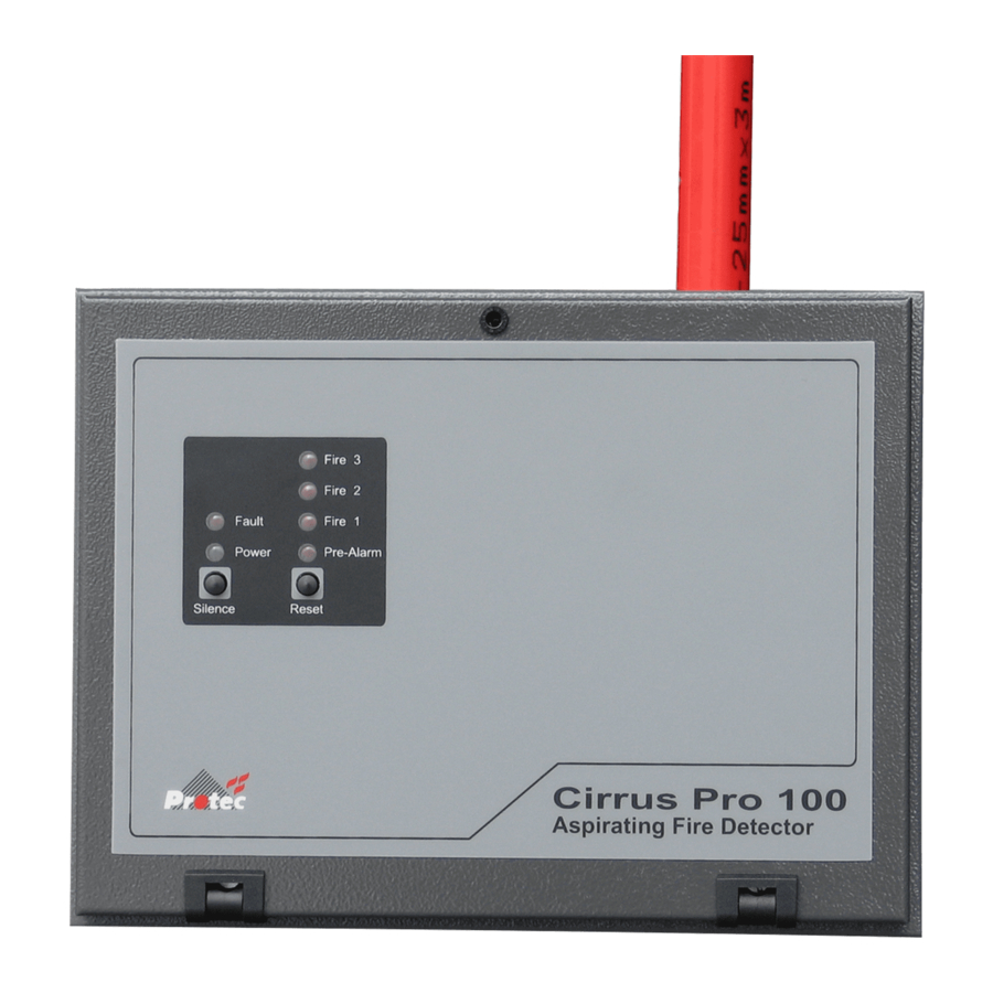
CirrusPro 100 Up to 100m of 25mm diameter sampling pipe. Single sampling pipe ‘inlet’ port. CirrusPro 200 Up to 200m of 25mm diameter sampling pipe. Four, sampling pipe ‘inlet’ ports. CirrusPro 200D As CirrusPro 200 with built in Display Panel (See CirrusPro RDP). -
Page 8: Factory Defaults
Factory defaults (For Reference) Detectors as supplied or after restoring to factory defaults have the following settings: If the node text is invalid, it is set to 'CirrusPRO' The node number, options and number of pipes aren't changed. High Security Codes set to 123456 Low Security Codes set to 112233 All pipes are set to latch at pre-alarm. - Page 9 Maximum Coverage 30’ x 30’ (9.144m x 9.144m) Per Sample Head or Point: Number of Zones: Pro 100 1 Zone Pro 200 1 Zone Pro 200+ 1 Zone Pro 200D 1 Zone Pro 200D+ 1 Zone Pro 200DSC Field Programmable up to 4 Zones Pro 200DSC+ Field Programmable up to 4 Zones Maximum Number of...
- Page 10 17.32” x 15.15” x 5.51” (440mm x 385mm x 140mm) Air Sampling System: The piping diagram for each system will be supplied by Protec Fire Detection (Export) or an authorized representative. This diagram will indicate tubing size, as well as approximate lengths to each sampling point.
-
Page 11: Ul And Ulc Information Pro X4
UL and ULC information Pro X4 The following information is required to ensure the units compliance with the UL listing for UL 268 & CAN/ULC-S529-02 Cloud Chamber Detection Principle: Maximum Intended Protected Area: 43,200 square feet (4013 square meters) 4 zones total 10800 square feet (1003.25 square meters) per zone 900 square feet (83.604 square meters) per sampling head or point... - Page 12 17.32” x 15.15” x 5.51” (440mm x 385mm x 140mm) Cabinet: The piping diagram for each system will be supplied by Air Sampling System: Protec Fire Detection (Export) or an authorized representative. This diagram will indicate tubing size, as well as approximate lengths to each sampling point. Gain Settings...
-
Page 13: Installation
Installation Equipment Received CirrusPro Aspirating Fire Detector Unit Vacuum Pump (packed separate with some models) Full Water Bottle (Triple De Ionised Water) Water Bottle Top with pipe connector Wall Mounting Template Allen key (or door keys on 200+, 200DSC, 200DSC+ and X4) Engineer’s Manual (This Manual) User Manual Installation Procedure... -
Page 14: General Cabling Requirements
General Cabling Requirements All wiring associated with the system must conform to the current Wiring Regulations, and cabling must conform to the relevant National Standards Specifications. Recommended cable separation for electromagnetic compatibility in buildings must be followed. Where screened cables are used it is important to ensure that screen continuity is maintained between cable segments. - Page 15 Double stacked Terminals for general connection: Fault/OP1/OP2/OP3/OP4: Changeover contacts All Rated: 0.3 A at 125 VAC; 1 A at 30V DC Auxiliary (VS) supply: 27V, Current limited to 300mA PTC protected IP1/IP2/IP3/IP4: Programmable Inputs: 4 monitored inputs for Isolate, Silence, reset and ‘Sensitivity Change’...
-
Page 16: Commissioning
Commissioning Before starting to commission any unit, it is necessary to verify that all the external wiring and pipe work has been fitted correctly and that the pipe work matches the pipe calculation results. The commissioning process is carried out using a PC. Most commissioning actions can be carried out with a display panel (DP), when fitted. -
Page 17: Using The Pc Interface
Using the PC Interface 3.2.1 Equipment Required for Commissioning with a PC 1. PC running CirrusPro Windows Software. 2. RS232 cable with Gender Changer as required. (9 Pin D type female to female wired 1 to 1 See illustration below) 3. -
Page 18: Running Cirruspro Software
3.2.3 Running CirrusPro Software Having checked that all the connections are correct, both pipe work and wiring, the system can now be commissioned: 1. Apply power to the detector unit. The PC can be powered when this occurs but it is usually better that the CirrusPro Software is not running. -
Page 19: Commissioning
3.2.4 Commissioning Double Click on the unit to be commissioned to display the security code entry: After entering the security code, all the information from the selected unit will be uploaded and one of the following forms displayed, depending on model: CirrusPro 100, 200, 200D, 200+,200D+ CirrusPro 200DSC, 200DSC+, X4 These screen shots show no fault or fire conditions. -
Page 20: The Commissioning Menu
3.2.6 The Commissioning Menu Clicking on ‘Commission’ on the toolbar displays the following list of items: To complete the commissioning it is necessary to follow this list as shown, from top to bottom. 3.2.7 Setting the Time Ensure that the PC time is correct before selecting this option. When selected the update is automatic, setting the unit time to the PC’s time, with the following confirmation window: or in the case of a communication failure 3.2.8 Pipe Scan... -
Page 21: Accept Airflow
3.2.9 Accept Airflow If the unit is a Pro 100 or Pro 200 (non scanning) then only one airflow will be enabled. Select ‘Ignore’ for any pipes not connected. The Air Speed should be set to the value given on the Pipe Calculation results, except on the CirrusPro X4 where it should always be at 100%. - Page 22 Sensitivity Settings The display shows the default Gain and Alarm Thresholds values. Pipe 1 is shown, changed by selecting the pull down menu. If the unit is a non-scanning version then the ‘Pipe’ dialog box will appear grey. Select the box to change any of the Gain or Threshold values, within limits of two rules: 1.
-
Page 23: I/O Settings
Time Zones When using Time Zones, each zone has its own set of gain and threshold values for each pipe. Each day is split into three time zones, the current zone is indicated by ‘>>’ when the menu is entered. The start times for the three zones each day are entered with the required gain and sensitivity levels for that zone. -
Page 24: Output Check
Inputs Every CirrusPro has connections for four inputs. Each of these can be monitored as Normally Open (default) or Normally Closed. Normally Closed is selected by checking the box adjacent to the Input number. See Section 7 for input specification. Inputs can be configured as one of the following: Unused –... -
Page 25: Editing Text
3.2.14 Editing Text The text for the unit, the pipe text and the alarm text are edited within this menu. If the unit is networked to an internal or external Display, text will appear on the display. Change the text by clicking in the relevant box and editing as required. - Page 26 The buzzer is used to indicate the test is about to begin. This is a slow ‘pip’ for 10 seconds once the delay is complete. The countdown is shown on the display. First test about to begin. Second test about to begin. The particles are now presented to the sample point and the timer counts showing the elapsed time.
-
Page 27: Print
3.2.16 Print This option will print the current set up to the PC printer selected. The standard Windows printer selection form is displayed. 3.2.17 Set Security Code / Set User Code The default High Security Code is 123456 and User code is 112233. -
Page 28: Options
3.2.19 Options Buzzer: The Buzzer is functional when this option is checked. Update Logo: This allows a customised logo to be downloaded to the display unit set to network number 128. To change the logo on multiple units, each must be set to 128 in turn. The file is opened using the standard Windows file menu. -
Page 29: Saving Data To The Unit
The Zone O/P Board is fitted with the CirrusPro 200DSC, 200DSC+ and X4. The MUX interface communicates directly to several models of fire alarm control panels manufactured by Protec Fire Detection PLC. Clock Calibrate: If it is found that the unit clock is running fast or slow, this can be used to correct the running of the clock. -
Page 30: Handling Detector Unit Data (The Network Menu)
Handling Detector Unit Data (The Network Menu) 3.3.1 Saving Data Any changes in the set up of a unit must be downloaded to it; this has to be done manually from the menu but is prompted when closing the connection where changes have not been saved. Any attempt to close the PC program, when changes have been made, displays a prompt: Selecting ‘Yes’... -
Page 31: Closing The Connection
At this point all data is uploaded from each detector unit on the network. It can take a few minutes due to the amount of data being transferred. This file should be returned to Protec for storage and future reference. Similarly, a file is opened from this menu for examination. -
Page 32: Commissioning By Display
Commissioning by Display The units can be commissioned using the internal or remote displays, if connected. Most of the PC functions are available from display units and are described in detail in the PC commissioning sections. The text at the bottom of the display corresponds to the push buttons below the display. By holding down a button, its function will auto-repeat. - Page 33 Pressing SEL moves the highlighting to the next editable section. and – increment and decrement the values. Node Number 128 is the default and can be set in the range 96 to 128. These numbers are for display units only. 128 should be included and then the numbers should increment down from 128. The Connect Node is the number of the detector unit that the display is linked to.
-
Page 34: Network And Language Settings Display Software V 1.12
3.4.2 Network and language settings display software V 1.12 This version of display software introduces foreign language versions and alters the access to the network setting menu. On powering up, the display shows the display software version number for a short time, then the Logo Menu. -
Page 35: Main Options Menu
3.4.3 Main Options Menu Engineers Menu Users Menu Only by entering the high security code can the system be commissioned. The menu options are limited with the user code, as shown on the right. Use the Down and Up Keys to move to the required option (Down only in User Menu). Press ‘Select’... -
Page 36: Real Time Graph
3.4.4 Real Time graph Shows a real time graph of the current particle and alarm levels showing about 5 minutes. Use + and – to view other Pipes (where available). 3.4.5 Unit options Use Up and Down to move the options, press select to change the option. -
Page 37: Airflow
3.4.7 Airflow Use Select (Sel) to highlight the section to be edited and + and – to increase or decrease its value. Change the airflow to increase or decrease the blower speed if the airflow is in fault. Refer to the pipe calculations for calculated values. -
Page 38: Event Log
3.4.9 Event Log The Event Log stores the last 128 events on the unit. The latest events are displayed first, with earlier events displayed by pressing Next. Pressing ‘Both’ changes the display to show just Fire events. Pressing ‘Fires’ changes the display to show just Fault events. -
Page 39: Sensitivity Settings
3.4.10 Sensitivity Settings Use Select (Sel) to highlight the section to be edited and + and – to increase or decrease its value. With scanning versions it is possible to change the pipe number and therefore, edit the sensitivity for all pipes. -
Page 40: Output Test
Inputs are be configured as one of the following: Unused – The input is ignored Isolate – Alarm relays are Isolated Reset – Reset the sensor from any latched state Disable – Shut down the CirrusPro Fault – External Fault input that indicates as External Fault Gain set –... -
Page 41: Historic Graph
3.4.13 Historic Graph The Historic Graph shows a period of about three days, with about 10 days stored. The amount of data is dependent on what has happened during the recording period. The amount of data stored increases during fire and pre alarm events. 3.4.14 Security Code On opening this screen, the display shows 0. -
Page 42: Service Information
3.4.16 Service Information Acceptable Values: Pump Pressure - > 5.7 psi Supply voltage - 19V to 30V LED current is - 0.26mA to 5.67mA Airflow Refer to Pipe Calculation Average time between fills Usually 4 to 6 days, depends on local conditions. 3.4.17 Reset Unit By selecting this option the unit carries out a full reset. -
Page 43: Servicing And Maintenance
Check that any fault reported previously has been attended to. • 4.1.2 Three-monthly Checks The following must be performed EVERY THREE MONTHS by Protec Fire Detection (Export) Ltd or an authorised representative: Check the Event Log to determine any abnormalities. -
Page 44: Data Menu
Note that most of the following can be carried out from a Display Unit on the CirrusPro network. See Section 3.4. See section 3.2.1 to 3.2.4 for initial set up of the PC connection and fault reporting. Rectify any faults in the Current Faults window, found during the power up sequence. Refer to the Fault Finding in Section 5. -
Page 45: Algotech Status
A timestamp can be added to the graph. 4.2.2 Algotech Status This shows the current values of the Algotech time averages and is only applicable when the Algotech option is switched on during the commissioning. See Section 3.2.11. Algotech values are based on current levels during power on. Recent changes are reflected in T1 to T3, otherwise the four values will be similar. -
Page 46: Event Log
4.2.3 Event Log The log stores up to 128 of the latest events since the event log was cleared. From the log: Confirm that water is taken every few days. When any fault occurred. The log can be displayed with just Fires or just Events by selecting the relevant tick boxes. The example shows both Fires and Faults are selected to be displayed. -
Page 47: Historic Graph
4.2.4 Historic Graph The Historic Graph shows a period of about three days, with about 10 days stored. The amount of data is dependent on what has happened during the recording period. Stored data increases during fire and pre alarm events. The data is downloaded from the unit. -
Page 48: Service Information
4.3.2 Service Information This lists the current values for various readings within the unit. If any measurements are close to unacceptable limits, corrective action should then be taken. See Section 6 for a list of faults and corrective actions. Operating the Commissioned button saves this data in the Site Information memory. Service Operations As well as confirming the status of the Cirrus Pro unit as shown in the sections above, the following Servicing actions must be carried out:... -
Page 49: Cleaning The Airflow Board
4.4.1 Cleaning the Airflow Board The airflow board is found in the flow path in the manifold of all models. In order to clean the airflow sensors it is necessary to release the manifold and drop it away from the sampling pipe. There are two or four screws holding the manifold in place depending on the model. -
Page 50: Replacing The Chamber Filters
4.4.2 Replacing the chamber filters The two chamber filters are be found by removing the two large Allen Key plugs on the Cirrus Pro cloud chamber. With the unit switched off, remove the Allen key plugs and remove the filters. Replace with new filters and refit the plugs (do not over tighten). -
Page 51: Networking
Networking The Cirrus Pro Network is based on Node Numbers in ranges allocated to specific devices: The system allows: 1 PC Unit Network Number 1 32 Detector Units Network Numbers 224 to 255 Default 255 32 Display Units Network Numbers 97 to 128 Default 128 Refer to the example system below: Detector... - Page 52 Displays can be set up to connect to a single Detector Node or to monitor all nodes and display information from any detector. Setting the Connect Node to 000 allows the display to monitor all the detectors. Setting the Connect Node to any value 224 to 255 automatically connects the display to that detector. For displays within detector enclosures, the Connect Node number is usually set to the associated Detector Node number.
-
Page 53: Fault Finding
Fault Finding Internal diagnostics monitor for faults that may arise during commissioning, service and normal running. Network related faults are covered in the previous section. Fault List Faults have been assigned codes that are used to identify the faults. The following is a list of all faults in Fault Code order: 1 Processor Fault This is indicated if a problem has been detected with the micro controller or the Read Only Memory... - Page 54 7 LED Fault The unit has detected that insufficient light is being received at the photodiode. This probably means that the LED, Photodiode or associated wiring has a fault. The chamber LED lights when a sample is taken, this can usually be seen illuminating through the mounting medium.
- Page 55 14 Unit Cold Fault The unit internal temperature has been lower than 1° C for 8 hours. The water could start to freeze. May also get water fill faults as unit too cold to fill. 15 Unit Disabled The unit has been shut down via a monitored input. See Section 3.2.12. 16 Expansion Board Fault A communication problem to expansion PCB has been detected.
-
Page 56: Indicating Fault Codes On The Detector Unit
Indicating Fault Codes on the Detector Unit The CirrusPro can pulse the Fault LED to indicate fault code of current Faults or the last fault if there are no current Faults. When the unit is in Fault, press and hold the Silence button. The Fault LED will illuminate for 5 seconds, then pulse a number of times indicating the fault code. -
Page 57: Detector Specification
Detector Specification Physical Data varies with model and are not given here Supply Voltage: 19 - 27VDC UL 1481 Approved. Humidity: 10 - 95%RH, non-condensing Temperature: 0 – 37.8° C IP Rating: IP30 Cable Access: 20mm knock Cable Termination: Screw terminal blocks (0.2 - 2.5mm2, 30 - 12AWG) Pipe ID: 19 to 25mm (preferred OD 25mm) - Page 58 BLANK PAGE 93-520-20 Issue 3.3 Page 58 of 60 CirrusPro Engineer’s Manual...
- Page 59 BLANK PAGE 93-520-20 Issue 3.3 Page 59 of 60 CirrusPro Engineer’s Manual...
- Page 60 Cirrus Pro Series Aspirating Fire Detectors Worldwide Manufacturer PROTEC FIRE DETECTION (EXPORT) LIMITED Protec House, Phone: +44 1282 717171 Churchill Way, Fax: +44 1282 717273 Nelson, E-mail: sales@protec.co.uk Lancashire, England. BB9 6RT. 93-520-20 Issue 3.3 Page 60 of 60 CirrusPro Engineer’s Manual...
Need help?
Do you have a question about the CirrusPro 200 and is the answer not in the manual?
Questions and answers