
Related Manuals for ABB H8138.K Series


Summary of Contents for ABB H8138.K Series
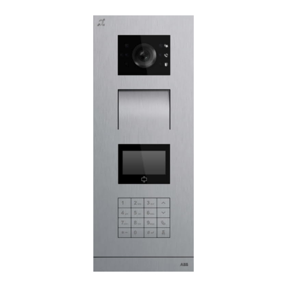
- Page 1 │ 2TMD041800D0014 22.07.2019 Product manual ABB-Welcome IP H8138.K-. IP keypad outdoor station H8138.K-.-02 IP keypad outdoor station...
-
Page 2: Table Of Contents
Table of contents Notes on the instruction manual ........................4 Safety ................................4 Intended use ..............................5 Environment ..............................7 ABB devices ............................7 Product description ............................8 Control elements ..........................8 Terminal description ........................... 9 Lock type and connection ........................ 10 Technical data ............................. - Page 3 Table of contents 11.3 Deployment guideline ........................29 11.4 Upgrading ............................29 11.5 Backup/Restore ..........................29 11.6 Malware prevention solution ......................29 11.7 Password rule ..........................29 │3 Product manual 2TMD041800D0014...
-
Page 4: Notes On The Instruction Manual
Please keep this manual in a safe place. If you pass the device on, also pass on this manual along with it. ABB accepts no liability for any failure to observe the instructions in this manual. Safety... -
Page 5: Intended Use
Intended use Intended use As part of the ABB-Welcome IP system, this device can only be used with accessories from that system. Security mode This outdoor station runs in "Security mode" by default to guarantee high security. In "Security mode", this outdoor station requires a certificate issued by the management software before it can function normally. - Page 6 Intended use Application Home Community Switch IP actuator IP touch 7 Guard unit IP keypad OS WipAP (Functional) LAN mode │6 Product manual 2TMD041800D0014...
-
Page 7: Environment
ABB devices All packaging materials and devices from ABB bear the markings and test seals for proper disposal. Always dispose of the packing materials and electric devices and their components via an authorized collection facility or disposal company. -
Page 8: Product Description
Product description Product description Control elements Function Camera Speaker and microphone integration Display module with ID/IC card reader Keypad End strip │8 Product manual 2TMD041800D0014... -
Page 9: Terminal Description
Product description Terminal description Function Reset button Micro USB update connector Plug-in clamps (DC+-GND) for standalone power supply Plug-in clamps (LOCK-GND) for door opener Plug-in clamps (COM-NC-NO) for floating output, door opener LAN (PoE) Connector for next module Connector for exit button Connector for the sensor used for door status detection Connector for 5"... -
Page 10: Lock Type And Connection
Product description Lock type and connection Lock type Operation type Voltage Wiring type Type A Electrical strike Power on to open 12 VDC/AC lock, 12V Type B Electrical strike 24 VDC/AC Type B Power on to open lock, 24V Type A Electrical rim Power on to open 12 VDC... -
Page 11: Technical Data
Technical data Technical data Designation Value Rating voltage 24 VDC Operating voltage range 20-27 V DC 27 V DC, 455 mA Rating current 24 V DC, 500 mA Operating temperature -40 °C…+55 °C Product dimensions 135 mm x 348.9 mm x 17.6 mm Display type Display size 57.8 mm ×... -
Page 12: Mounting/Installation
Mounting/Installation Mounting/Installation Warning Electric voltage! Dangerous currents flow through the body when coming into direct or indirect contact with live components. This can result in electric shock, burns or even death. – Disconnect the mains power supply prior to installation and/or disassembly! –... -
Page 13: Mounting
Mounting/Installation Mounting 7.2.1 Preparation Use gloves to protect yourself against cuts. 7.2.2 Wiring │13 Product manual 2TMD041800D0014... -
Page 14: Surface-Mounted Installation
Mounting/Installation 7.2.3 Surface-mounted installation 40 mm 71 mm 7.2.4 Flush-mounted installation 1. Flush-mounted without pre-installation box 46 mm 117 mm │14 Product manual 2TMD041800D0014... - Page 15 Mounting/Installation 2. Flush-mounted with pre-installation box 126 m m 68 m m │15 Product manual 2TMD041800D0014...
-
Page 16: Cavity Wall Installation
Mounting/Installation 7.2.5 Cavity wall installation │16 Product manual 2TMD041800D0014... - Page 17 Mounting/Installation Dismantling Installation situations Note The following installation situations must be avoided without fail to ensure picture quality: ■ Direct light ■ Direct sunlight ■ Extremely bright picture background ■ Highly reflective walls on the opposite side of the door station ■...
-
Page 18: Commissioning
Commissioning Commissioning Accessing the "Menu" screen In standby mode, press [#*] + system password + [#] to access the "Menu" screen. Note The system password must be changed the first time you access "Menu" screen. (The system default is 345678. This password should only be used for initial setting work and should be changed to another password. -
Page 19: Engineering Settings
Commissioning Engineering settings On the "Menu" screen, click "Engineering settings" to access the corresponding screen. 8.2.1 Engineering settings overview Level 1 Level 2 Level 3 Option ■ OS = Outdoor station Device type ■ GS = Gate station Device attribute ■... -
Page 20: Access Control Settings
Commissioning Access control settings On the "Menu" screen, click "Access control" to access the corresponding screen. 8.3.1 Access control overview Level 1 Level 2 Level 3 Option Change public password The system default is 123456 ■ Enable public Password password ■... -
Page 21: System Settings
Commissioning System settings On the "Menu" screen, click "System settings" to access the corresponding screen. 8.4.1 System settings overview Level 1 Level 2 Level 3 Option ■ ■ Relatively low ■ Voice volume Medium ■ Relatively high (default) ■ High ■... - Page 22 Commissioning Level 1 Level 2 Level 3 Option L1 LOCK-GND 1...10 s Unlock time L2 NO-NC-COM 1...10 s Off (default) Door status ■ alarm ■ On (alarm sound) ■ Off (default) Temper alarm ■ Off (default) Call forward (to guard unit) System settings ■...
-
Page 23: Logical Address Setting
Commissioning Logical address setting The call mode should be set to "logical address" before use. On the "Menu" screen, click "Logical address settings" to access the corresponding screen. Enter "Logical address" + [\/] + "Physical address"+ [#] to add a new one. Modify Enter "Logical address"... -
Page 24: Operation
Operation Operation Calling a resident [1] Device type = OS In standby mode, enter the room no. (e.g. 0101), press [*] to end the call. [2] Device type = GS In standby mode, enter the building no. + room no. (e.g. 020101), press [*] to end the call. Forward to GU If "Call forward"... -
Page 25: Releasing The Lock
Operation Releasing the lock 9.3.1 Release the lock by swiping ID/IC cards Please enroll the ID/IC cards before use. Please see the "Access control overview" chapter for more details. Swipe registered ID/IC cards near the area (see diagram below) to release the lock. ID card specification Operating frequency 13.56 MHz... -
Page 26: Releasing The Lock By Pressing The Exit Button
Operation 9.3.2 Releasing the lock by pressing the exit button Press an exit button connected to this outdoor station to release the lock. Exi t b u tto n 9.3.3 Releasing the lock by entering the public password The "public password" must be enabled before use. Please see the "Access control overview" chapter for more details. -
Page 27: Fcc
This device complies with Part 15 of the FCC Rules. Operation is subject to the following two conditions: (1) this device may not cause harmful interference, and (2) this device must accept any interference received, including interference that may cause undesired operation. Only operate the device in accordance with the instructions supplied. -
Page 28: Cyber Security
H8138.K-. product, the network, its system and interfaces against any kind of security breaches, unauthorized access, interference, intrusion, leakage and/or theft of data or information. ABB Ltd and its affiliates are not liable for damages and/or losses related to such security breaches, unauthorized access, interference, intrusion, leakage and/or theft of data or information. -
Page 29: Deployment Guideline
Malware prevention solution The H8138.K-. device is not susceptible to malware, because custom code cannot be executed on the system. The only way to update the software is by firmware upgrades. Only firmware signed by ABB can be accepted. 11.7 Password rule The user must change the engineering password when accessing the engineering settings for the first time. - Page 30 We reserve the right to at all times make technical changes as well as changes to the contents of this document without prior notice. The detailed specifications agreed to at the time of ordering apply to all orders. ABB accepts no responsibility for possible errors or incompleteness in this document.
- Page 31 Km 9 National Highway 1A , The detailed specifications agreed P.O.Box 11070 Dubai-UAE Hoang Liet, Hoang Mai, Hanoi, upon apply for orders. ABB accepts T : +971 4 3147 586 Vietnam no responsibility for possible errors F : +971 4 3401 541 T : +84 4 3861 1010 or incompleteness in this document.
- Page 32 Error! Use the Home tab to apply Überschrift 1 to the text that you want to appear here. © Copyright 2019 ABB All rights reserved │32 Product manual 2TMD041800D0014...
Need help?
Do you have a question about the H8138.K Series and is the answer not in the manual?
Questions and answers