
Related Manuals for ABB H8131.P Series


Summary of Contents for ABB H8131.P Series
- Page 1 2TMD041900D0015 │ 26.12.2024 Product manual ABB-Welcome IP H8131.P.-. Mini Video OS H8136.P.-. Mini Video OS...
- Page 2 Tabl e of contents Notes on the instruction manual ......................... 4 Safety ................................. 4 Intended use ............................... 4 Environment ............................... 5 ABB devices ............................ 5 Product description ............................. 6 Device type ............................. 6 Control elements ..........................7 Terminal description ........................8 Lock type and connection .......................
- Page 3 Table of contents 8.2.4 Viewing the version ........................... 46 8.2.5 Configuring the physical address ..................... 47 8.2.6 Configuring the IP address ....................... 49 8.2.7 Configuring the lock ........................... 50 8.2.8 Configuring the card mode ........................ 51 8.2.9 Configuring the "Time sync" function ....................52 8.2.10 Configuring the trusted devices ......................
- Page 4 Please keep this manual in a safe place. If you pass the device on, also pass on this manual along with it. ABB accepts no liability for any failure to observe the instructions in this manual. Safety...
- Page 5 ABB devices All packaging materials and devices from ABB bear the markings and test seals for proper disposal. Always dispose of the packing materials and electric devices and their components via an authorized collection facility or disposal company.
- Page 6 Product description Product description Device type Size (HxWxD) Article Product ID Product name Colour number Unit: mm H81313P1-A 2TMA130010A0001 Mini video outdoor station, Aluminum 99 x 168 x 26 1 gang, ID, SM alloy H81313P2-A 2TMA130010A0004 Mini video outdoor station, Aluminum 99 x 168 x 26 2 gang, ID, SM...
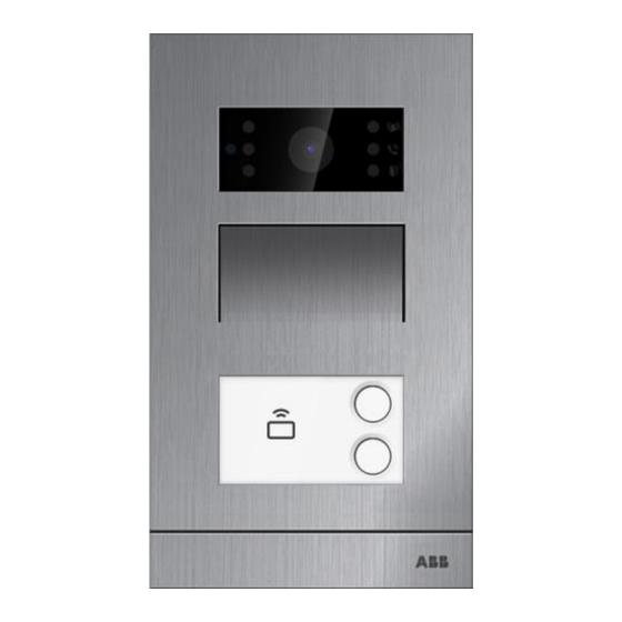
- Page 7 Product description Control elements Description Ring indicator Indicator flashes slowly: ringing Indicator flashes quickly: busy line Call indicator Unlock indicator Speaker and microphone integration Call button Label field Integrated ID card reader │7 Product manual 2TMD041900D0015...
- Page 8 Product description Terminal description EXIT AGND LOCK NC COM NO GND DC+ Description Connector for the sensor used for door status detection Connector for exit button Plug-in clamps (LOCK...AGND) for door opener Plug-in clamps (COM...NC...NO) for floating output Plug-in clamps (DC+...GND) for standalone power supply LAN (PoE) │8 Product manual 2TMD041900D0015...
- Page 9 Product description Lock type and connection Lock type Operation type Voltage Wiring type Electrical strike ⎓ Power on to open Type A/B 12 V lock, 12V Electrical strike ⎓ Type B Power on to open 24 V lock, 24V Electrical rim ⎓...
- Page 10 Technical data Technical data Designation Value ⎓ Rating voltage 24 V ⎓ Operating voltage range 20-27 V ⎓ 27 V , 310 mA Rating current ⎓ 24 V , 350 mA -40 °C…+55 °C Operating temperature 99 mm x 168 mm × 26 mm (H8131.P.-.) Product dimensions 105 mm x 180 mm ×...
- Page 11 Mounting/Installation Mounting/Installation Warning Electric voltage! Dangerous currents flow through the body when coming into direct or indirect contact with live components. This can result in electric shock, burns or even death. – Disconnect the mains power supply prior to installation and/or disassembly! –...
- Page 12 Mounting/Installation Mounting 7.2.1 Preparation Use gloves to protect yourself against cuts. 7.2.2 Installation height 1.5 m 5 feet │12 Product manual 2TMD041900D0015...
- Page 13 Mounting/Installation 7.2.3 Installation situation Note The following installation situations must be avoided without fail to ensure picture quality: ■ Direct light ■ Direct sunlight ■ Extremely bright picture background ■ Highly reflective walls on the opposite side of the door station │13 Product manual 2TMD041900D0015...
- Page 14 Mounting/Installation 7.2.4 Surface-mounted installation Product dimension 99 mm 26.5 mm 78 mm 62 mm 60 mm Surface-mounted on the wall Mounting screw x 4 ⌀ Screw shaft: Screw length: ≥ 25 mm │14 Product manual 2TMD041900D0015...
- Page 15 Mounting/Installation Surface-mounted on the box (e.g. VDE box) Mounting screw x 4 ⌀ Screw shaft: Screw length: ≥ 25 mm │15 Product manual 2TMD041900D0015...
- Page 16 Mounting/Installation 7.2.5 Flush-mounted installation Product dimension 99 mm 45 mm 105 mm 53 mm 99 mm Flush-mounted with pre-installation box Mounting screw x 4 ⌀ Screw shaft: Screw length: 25 mm ≥ │16 Product manual 2TMD041900D0015...
- Page 17 Mounting/Installation 7.2.6 Cavity wall installation Product dimension 92 mm 105 mm 43 mm 90 mm 97 mm Mounting Mounting screw x 4 ⌀ Screw shaft: Screw length: ≥ 25 mm │17 Product manual 2TMD041900D0015...
- Page 18 Mounting/Installation 7.2.7 Replacing the nameplate │18 Product manual 2TMD041900D0015...
- Page 19 Commissioning Commissioning Configure the settings on Indoor Station 8.1.1 Enter engineering mode of Outdoor Station Note The Outdoor Station must be on the same network as the Indoor Station. Please follow the steps below: [1] Power on the Outdoor Station, wait until all 3 LED indicators go out. [2] Press and hold the first pushbutton for 5 seconds until all 3 LED indicators flash.
- Page 20 Commissioning 8.1.2 Accessing the "Outoodr Stations" screen Please follow the steps below: [1] Ensure that the Outdoor Station is in engineering mode. [2] On the "Settings" screen of the panel, tap "Advanced Settings". [3] Tap "Outdoor Stations" to access the corresponding screen. Note The Outdoor Station will exit engineering mode if no operation is carried out for 5 minutes.
- Page 21 [3] Tap "Set device details". [4] Enter the block number (001…999) and the device number (01…64). [5] Select the network type, it can set to "DHCP", "Customizable address" or "ABB Legacy". ■ If "ABB Legacy" is selected, IP address will be "10.0.x.x".
- Page 22 Commissioning Configuring the 2nd Outdoor Station 1. Location of IP Actuator = Internal In this case, the 2nd OS is connected to the router in the apartment (see the diagram below). Please follow the steps below: [1] On the "Outdoor Stations" screen, go to the "Device setting" section, select "2nd OS" from the drop-down list.
- Page 23 Commissioning [3] Select "Internal IP gateway". [4] Enter the device number (1…32). [5] Select the network type, it can set to "DHCP", "Customizable address" or "ABB Legacy". ■ If "ABB Legacy" is selected, IP address will be "10.0.x.x". [6] Tap "Save & Close".
- Page 24 Commissioning 2. Location of IP Actuator = External In this case, the 2nd OS is connected to the switch outside the apartment (see the diagram below). Please follow the steps below: [1] On the “Outdoor Stations” screen, go to the “Device setting” section. [2] Select “2nd OS”...
- Page 25 [5] Enter the block number (001…999), floor number (01…63), apartment number (01…32) and device number (01…02). [6] Select the network type, it can set to "DHCP", "Customizable address" or "ABB Legacy". ■ If "ABB Legacy" is selected, IP address will be "10.0.x.x".
- Page 26 Commissioning 8.1.4 Configuring the lock 1. Configuring the default lock Please follow the steps below: [1] On the "Outdoor Stations" screen, go to the "Lock Management" section, select the lock type from the drop-down list. ■ It can be set to "Lock-GND", "NO-NC-COM" or "IP Actuator". ■...
- Page 27 Commissioning 2. Configuring the subsidiary lock Please follow the steps below: [1] On the "Outdoor Stations" screen, go to the "Lock Management" section, select the lock type from the drop-down list. ■ It can be set to "Lock-GND", "NO-NC-COM" or "IP Actuator". ■...
- Page 28 Commissioning 8.1.5 Configuring the "Door alarm" function Please follow the steps below: [1] On the "Outdoor Stations" screen, go to the "Door Alarm" section, tick the check box to enable the functions. ■ If the "Detection Alarm" function is enabled, the panel will send an alarm to SmartAP when the door is open for longer than 120 seconds (a sensor should first be connected to the Outdoor Station).
- Page 29 Commissioning 8.1.6 Configuring the "Anti-flicker" function Please follow the steps below: [1] On the "Outdoor Stations" screen, go to the "Anti-flicker settings" section, select the refresh rate from the drop-down list. It can be set to "60 Hz" or "50 Hz". │29 Product manual 2TMD041900D0015...
- Page 30 Commissioning 8.1.7 Configuring the language Please follow the steps below: [1] On the "Outdoor Stations" screen, go to the "Outdoor Station Language" section, select the language from the drop-down list. │30 Product manual 2TMD041900D0015...
- Page 31 Commissioning 8.1.8 Configuring the ringtone volume Please follow the steps below: [1] On the "Outdoor Stations" screen, go to the "Ringtone volume" section, select the ringtone volume (1...3) │31 Product manual 2TMD041900D0015...
- Page 32 Commissioning 8.1.9 Configuring the "Button tone" function Please follow the steps below: [1] On the "Outdoor Stations" screen, go to the "Sound" section, tick the check box to enable the function. [2] Go to the "Voice Volume" section, select the voice volume (1...5). │32 Product manual 2TMD041900D0015...
- Page 33 Commissioning 8.1.10 Configuring the "Voice prompts" function Please follow the steps below: [1] On the "Outdoor Stations" screen, go to the "Sound" section, tick the check box to enable the function. [2] Go to the "Outdoor Station Language" section, select the language. [3] Go to the "Voice Volume"...
- Page 34 Commissioning 8.1.11 Configuring the push buttons Please follow the steps below: [1] On the "Outdoor Stations" screen, go to the "Buttons set-up" section, select the column number. This setting is only available when detecting the bar push-button module on the Outdoor Station.
- Page 35 Commissioning [5] Select the function from the drop-down list. It can be set to "Call", "Turn on the light" or "None". [6] Select the device type from the drop-down list. It can be set to "Indoor Station" or "Phone Guard Unit". [7] Enter the address according to the device type.
- Page 36 Commissioning 8.1.12 Configuring the "Time sync" function Please follow the steps below: [1] On the "Outdoor Stations" screen, go to the "Buttons set-up" section, select the sync time method from the drop-down list. ■ If "Sync with SmartAP" is selected, the Outdoor Station will sync the time from the management software.
- Page 37 Commissioning 8.1.13 Configuring call forward This function can be available only when "Device type" is set to "OS". Please follow the steps below: [1] On the "Outdoor Stations" screen, go to the "Call Forward" section, tick the check box to enable the function.
- Page 38 Commissioning 8.1.14 Configuring Card mode This chapter applies to the Outdoor Station which supports IC cards. If "Safe mode" is enabled, when you register an IC card on the Outdoor Station, a security key will be written to the IC card to achieve higher security. Please follow the steps below: [1] On the "Outdoor Stations"...
- Page 39 Commissioning 8.1.15 Viewing the information Please follow the steps below: [1] On the “Outdoor Stations” screen, scroll down to view the information. Description Mainboard version and MCU version Serial number Signature │39 Product manual 2TMD041900D0015...
- Page 40 Commissioning 8.1.16 Updating the firmware ■ The Outdoor Station can update the firmware via the Indoor Station which supports micro SD card. The Outdoor Station must exit engineering mode before the firmware is upgraded. ■ Updating the firmware via the Indoor Station Please follow the steps below: [1] On the "Outdoor Stations"...
- Page 41 Commissioning [5] "Loading…" will be displayed to indicate that the upgrade is in progress. [6] "Push success!" will be displayed if the upgrade is successful. │41 Product manual 2TMD041900D0015...
- Page 42 Commissioning Configure the settings on "Smart Access Point" 8.2.1 Adding the Outdoor Station Note Only an Outdoor Station without a certificate can be added by SmartAP. This Outdoor Station will lose its certificate if its physical address is changed. The Outdoor Station needs to be powered on before being added. On the "Smart Access Point"...
- Page 43 Commissioning [2] Click "Add device". [3] Select the device type from the drop-down list. It could be set to "Outdoor station" or "Second-confirm station". [4] Enter the device address, [5] This function is available only when device type is set to "Second-confirm station". ■...
- Page 44 Commissioning 8.2.2 Accessing the designated Outdoor Station screen Please follow the steps below: [1] On the "Main Menu" screen, click "Door Entry System". [2] Click "Outdoor Station". [3] Click the designated Outdoor Station to access the corresponding screen. │44 Product manual 2TMD041900D0015...
- Page 45 Commissioning 8.2.3 Viewing the serial number Please follow the steps below: [1] On the designated Outdoor Station screen, go to the "Serial No." section to view the serial number. │45 Product manual 2TMD041900D0015...
- Page 46 Commissioning 8.2.4 Viewing the version Please follow the steps below: [1] On the designated Outdoor Station screen, go to the "Version" section to view the firmware version. │46 Product manual 2TMD041900D0015...
- Page 47 Commissioning 8.2.5 Configuring the physical address 1. Outdoor Station Please follow the steps below: [1] On the designated Outdoor Station, go to the "Additional settings" section, click "Physical address". [2] Go to the "Device type" section, select "Outdoor Station". [3] Enter the block number (001…999) and the device number (01…64). [4] Click "Save".
- Page 48 Commissioning 2. Second-confirm Station Please follow the steps below: [1] On the designated Outdoor Station, go to the "Additional settings" section, click "Physical address". [2] Go to the "Device type" section, select "Second-confirm Station". [3] Enter the physical address. [4] Click "Save". │48 Product manual 2TMD041900D0015...
- Page 49 Commissioning 8.2.6 Configuring the IP address Please follow the steps below: [1] On the designated Outdoor Station screen, go to the "Additional settings" section, click "IP address". [2] Select the network type, it can set to "DHCP" or "Static address. ■...
- Page 50 Commissioning 8.2.7 Configuring the lock Please follow the steps below: [1] On the designated Outdoor Station screen, go to the "Additional settings" section, click "Door lock setting". [2] Set the lock type of default lock, it can be set to "Lock-GND", "NO-NC-COM" or "IP Actuator".
- Page 51 Commissioning 8.2.8 Configuring the card mode Please follow the steps below: [1] On the designated Outdoor Station screen, go to the "Additional settings" section, click "Card mode setting". [2] Tick/untick the check box to enable/disable the function. ■ If the function is enabled, when you register an IC card on the Outdoor Station, a security key will be written to the IC card to achieve higher security.
- Page 52 Commissioning 8.2.9 Configuring the "Time sync" function Please follow the steps below: [1] On the designated Outdoor Station screen, go to the "Additional settings" section, click "Time synchronization". [2] Tick/untick the check box to enable/disable the function. ■ If the function is enabled, the Outdoor Station will sync the time from the management software.
- Page 53 Commissioning 8.2.10 Configuring the trusted devices If you want to release the lock on the Outdoor Station, you need to check: ■ The Indoor Station and the Outdoor Station have been signed on "Smart Access Point". ■ The Indoor Station has been added on the trusted list on the Outdoor Station. Please follow the steps below to add the trusted device: [1] On the designated Outdoor Station screen, go to the "Additional settings"...
- Page 54 Commissioning [3] Select the designated Indoor Stations to trusted list. [4] Click "√" to confirm. [5] [Optional] You need to enable the "Trust this management software" function if you want this Outdoor Station to unlock in the event of an emergency. [6] Click "Save".
- Page 55 Commissioning 8.2.11 Updating the firmware 1. Local firmware update Please follow the steps below: [1] On the designated Outdoor Station screen, click "Local firmware update". [2] Click "Browser" to select the update file (.img). [3] Click "Browser" to select the signature file (.sig). [4] Click "Save".
- Page 56 Commissioning [6] Update status will be displayed. [7] Click "Close" when the update is completed. │56 Product manual 2TMD041900D0015...
- Page 57 Commissioning 2. Online firmware update Please follow the steps below: [1] On the designated Outdoor Station screen, click "Online firmware update". [2] Current firmware version will be displayed. [3] "Current firmware is up to date" will be displayed if no newer version is available. │57 Product manual 2TMD041900D0015...
- Page 58 Commissioning Card management The chapter applies to the Outdoor Station integrated with ID or IC card reader. Note It is recommended that ID or IC cards are created and maintained using local outdoor station or management software only. 1. Card management on local outdoor station Initiate status When the device is powered on the first time, all 3 indicators flash in red, orange &...
- Page 59 Commissioning Normal settings After entering the settings, following functionalities can be implemented: Function Action Unlock indicator Swipe admin card 1x Orange flashes 1x Enrol user Swipe user card 1x Green Swipe admin card 2x Orange flashes 2x Delete user Swipe user card 1x Green Swipe admin card 3x Orange flashes 3x...
- Page 60 Commissioning Technical data of ID card Used frequency Standard 125KHz EM4100, EM4205, EM4305, EM4450, TK4100, T5567/T5577 Technical data of IC card Operating frequency 13,56 MHz Standard ISO 14443A Support card Mifare one S50/S70, Mifare desfire EV1/EV2 Output format Wiegand 26/34 bit Note A maximum of 64 ID cards can be supported.
- Page 61 Commissioning Restoring to factory default Please follow the steps below: [1] Power on the Outdoor Station, wait until all 3 LED indicators go out. [2] Within 2 minutes of powering on the Outdoor Station, press and hold the first pushbutton for 5 seconds until all 3 LED indicators flash.
- Page 62 Although ABB provides functionality testing on the products and updates that we release, you should institute your own testing program for any product updates or other major system updates (to include but not limited to code changes, configuration file changes, third party software updates or patches, hardware change out, etc.) to ensure that the security measures...
- Page 63 Malware prevention solution The device is not susceptible to malware, because custom code cannot be executed on the system. The only way to update the software is via firmware upgrades. Only firmware signed by ABB can be accepted. │63 Product manual 2TMD041900D0015...
- Page 64 We reserve the right to at all times make technical changes as well as changes to the contents of this document without prior notice. The detailed specifications agreed to at the time of ordering apply to all orders. ABB accepts no responsibility for possible errors or incompleteness in this document.
- Page 65 Contact us Notice We reserve the right to at all times ABB Xiamen Smart Technology Co., Ltd. make technical changes as well as No. 881, FangShanXiEr Road, Xiang’An Industrial changes to the contents of this Area, Torch Hi-Tech Industrial Development document without prior notice.
Need help?
Do you have a question about the H8131.P Series and is the answer not in the manual?
Questions and answers