
Related Manuals for Mikrofill Ethos 28 Series


Summary of Contents for Mikrofill Ethos 28 Series
- Page 1 Installation and Operating manual Ethos 28cc Ultra High Efficiency Gas Fired Condensing Combination Boiler...
-
Page 2: Table Of Contents
Contents 1. Why choose Mikrofill? ........ 6 2. Safety Considerations........ 7 3. Symbols ............ 7 3.1 Gas Safety........... 7 4. Electrical Supply ........7 5. Terms of Warranty ........8 6. Commissioning Certificate ......8 6.1 Requirements for the system quality ..... 8 7. - Page 3 17. Flues and Ventilation ......18 17.1 Maximum Flue Lengths ......18 17.2 Available Flue Components...... 20 17.3 Pluming ........... 21 17.4 Condensate in the Flue......21 17.5 Flue Options..........21 17.6 Installing a Concentric Flue ...... 21 17.7 Vertical flue Installations......
- Page 4 27. Installer Programming......39 28. Outside Temperature Control....40 28.1 Flow Temperature at + 20°C...... 40 28.2 Outside Temp. Control at - 1°C....41 28.3 Minimum pump speed....... .41 28.4 Maximum pump speed....... 41 28.5 Flow temperature secondary circuit... 41 28.6 Service counter.......... 41 28.7 Pump continuous........
- Page 5 37.10 Engineers button........57 37.11 Test button..........57 37.12 General............ 57 38. Programming Menu options ..58 38.1 Party............58 38.2 Hot Water Temperature......58 38.3 Day temperature function......58 38.4 Time/day function........58 38.5 Setting the ch timer........58 38.6 Setting the hw timer........
- Page 6 Table 9 Ventilation..........28 Table 10 Expansion Vessel Req......29 Table 11 System Contents........30 Table 12 Programming Functions......39 Table 13 Installer Functions........39 Table 14 Minimum & Maximum fan speeds... 48 Table 15 CO Outputs........
- Page 7 Work Act it is a requirement to provide information on substances hazardous to health (COSSH Regulations). Mikrofill takes every reasonable care to ensure that these products are designed and constructed to meet these general safety requirements, when properly used and installed.
-
Page 8: Safety Considerations
Gas Safety Regulations (as amended), Building Regulations, Model Water Bylaws and the Building Standards (Scotland) Regulations. Mikrofill shall not be responsible for any damage or loss resulting from failure to carefully observe the instructions given. The boiler, except for commissioning purposes, should not be left operating without the casing being attached and firmly secured 3. -
Page 9: Electrical Supply
If plastic pipes are used to connect the boiler to radiators or under floor heating, it is essential that only those types of plastic pipe that incorporate an oxygen diffusion barrier be used. If such pipes are not used, the Mikrofill guarantee will become null and void. -
Page 10: Expansion Vessels9
Select an expansion vessel that matches the volume of the CH system and the static pressure. Please contact Mikrofill Technical Department for assistance is required. Installation should comply with BS7074 part 1 and BS5449. -
Page 11: Introduction
7. Introduction The boiler features the very latest in technology. Developed around an innovative back panel the boiler uses laser welded waterways to interconnect the boilers main components. To facilitate ease of servicing stainless steel coiled heat exchanger and other major components are simply plugged into the panel. -
Page 12: Technical Information
8.2 Ethos 28cc This unit has a built-in heat secondary heat exchanger and Hot water production is continuous. The unit has a variable capacity of 20 to 100%, while the maximum capacity can be set and adapted to the capacity of the CH system. 10. - Page 13 Table 3 Capacities and Weights Model EC23 Heating Water Capacity litres Heating Water Coil Capacity (S models) Litres Weight (empty) Table 4 Hot Water Specifications Model EC23 Maximum Rated Input 28.0 Modulating Output 3.4-28 Hot Water Flow rates at .ô 30K (S type) L/min 13.4 Maximum Tap Water Pressure...
-
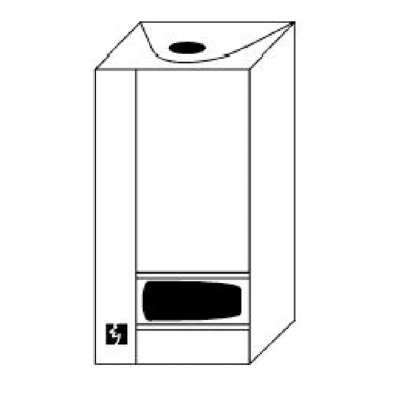
Page 14: Unpacking & Items Supplied
Installation manual (to be left with the boiler). Replacement fuses (located top left of control panel). Vent key. Mounting bracket. Outside air temperature sensor 13. Accessories The following items are also available from Mikrofill at extra cost. Colour coded 1/4 Turn Isolating Valves. Stainless Steel Flexible Pipe Connections. -
Page 15: Operation
Condensate sump pump for below ground installations. N.B. LPG installations must not be installed below ground level. Mikrofill servicing software and RS 2323 interface cable for connection to a PC. Mikrofill modulating room sensor. Mikrofill Cable for connecting three way diverter valve (external to boiler). -
Page 16: Variable Controlled Output
14.1 Variable Controlled Output The microprocessor controlled modulation system with integral fault diagnostic facility, ensures that optimum efficiency is maintained when operating in both heating and DHW modes. The premixing radiant burner modulates according to the required heat output. A 24-Volt, high efficiency fan is used with a variable speed and power capacity; if the heat demand decreases, the fan will turn at a lower speed, which results in a lower power consumption. -
Page 17: Timber Framed Dwellings
When installing the boiler into a timber framed dwelling, it must be fitted in accordance with the British Gas publication ‘ Guide for Gas Installations in Timber Framed Housing’ ref. DM2. For further advice contact the Mikrofill Technical Helpline. 16. Hydraulic Connections 16.1 First Fixing Pipe-work All the pipe-work and wiring connections enter at the bottom of the unit. -
Page 18: Type ' Hs' Connections
1) Cable Gland 2) Syphon Flush (No permanent connection required) 3) Heating Flow ~ 22mm 4) Additional Cable Entry Point 5) Gas Inlet ~ 15mm. 6) Heating Return ~ 22mm. 7) Condensate Discharge ~ ¾ M.I. 16.3 Type ’ HS’ Connections. 1) Cable Gland 2) Syphon Flush (No permanent connection required) 3) Heating Flow ~ 22mm... -
Page 19: Checks Before Siting
16.6 Checks Before Siting Before commencing to install this appliance ensure the design specification complies with all of the requirements contained in these installation and servicing instructions and any statutory documents which may apply. 16.7 Fixing the boiler. When unpacking the unit for the first time, take adequate precautions to protect the surrounding floor coverings. -
Page 20: Flues And Ventilation
Install the Ethos 29cc as close as possible to the hot water taps to avoid the hot water pipes from becoming too long. This prevents unnecessary waste of water. When you are satisfied the location meets all the required criteria mark out the wall for required fixing points. -
Page 21: Pluming
The available lift may be calculated from the Thermal lift graph and deducted from the total calculated flue resistance. For installations requiring greater flue lengths - please contact the Mikrofill technical department for advice. The flue should terminate with a suitable terminal. -
Page 22: Condensate In The Flue
2m above the level of any ground, balcony, flat roof, or place to which people have access, or there is a likelihood of accidental contact by persons or damage to the terminal, a suitable guard MUST be fitted. Terminal guards are available from Mikrofill. 17.4 Condensate in the Flue Condensate formed must be cleared from the flue system and adequate care is required to ensure all flue pipes are self draining. - Page 23 23, or where pluming is a nuisance. The Mikrofill flue system has been designed to overcome this and the 80mm P.P.S. flue pipe may be simply re-routed to terminate in a more suitable location. To do this simply...
-
Page 24: Vertical Flue Installations
Please contact Mikrofill for further advice. 17.8 Modular Installations For multiple boiler (modular) installations Mikrofill supply a range of larger diameter flues. Sizes are available in 150mm, 200mm and 250mm. For assistance in flue design and specification please call the Mikrofill technical department. -
Page 25: Fan Flued Terminal Positions
EPDM rubber seal rings located in the socket component. To aid assembly and assurance that the joints have been fully pushed home, the seal rings and make ends of tubes and fittings should be lightly lubricated with silicone grease. Additional 80/125mm concentric flues tubes and fittings are available 17.9 Fan Flued Terminal Positions... -
Page 26: Gas Supply
Terminal Positions Min distance A: Directly below an opening window or other 300mm opening, e.g. air brick Directly above an opening window or other opening, 300mm e.g. air brick B: Below gutters, soil pipes or drain pipes. 75mm C: Below eaves 200mm D: Below balconies or car port roof 200mm... -
Page 27: Conversion To Lpg
18.4 Conversion to LPG If the appliance is being used with LPG then a conversion kit is available from Mikrofill. The contents of the LPG conversion kit include the following items: 1 x Propane injector 5.7mm 1 x Injector 3.5mm 1 x 10mm plastic air box plug (for EC 16 &... -
Page 28: Air Supply
19. Air Supply 19.1 Concentric Flue If installed with a concentric flue and as a room sealed appliance the boiler does not require that room or internal space to have a permanent air supply. 19.2 Conventionally Flue Safe, efficient and trouble-free operation of conventionally flued gas boilers is dependant on the provision of an adequate supply of fresh air to the room in which the appliance is installed. -
Page 29: Expansion Vessel
The boilers are intended to be used in conjunction with FULLY PUMPED, SEALED systems subject to the requirements below. They are NOT SUITABLE for use on gravity circulation systems. The boiler must not be used for direct hot water supply. Under floor heating: Despite the low boiler flow temperatures feature, in the event of control and/or mechanical failure or incorrect adjustment, to prevent damage to the installation or... -
Page 30: Hydraulic Resistance
Mikrofill will not accept any liability for damage caused to the boiler should this situation occur. If the connection to an existing drain is not possible, the condensate may be discharged in to a purpose-built soak away. - Page 31 Typical installation serving domestic hot water and heating using integral expansion vessel and modulating circulating pump. Hot water production has priority controlled by spring return to heating diverter valve wired to boiler. Flow temperature to hot water is constant temperature to heating may be fixed or variable (weather compensated).
-
Page 32: Electrical Connections
21. Electrical Connections The boiler has a “ Wieland” plug connector for connection to the mains as part of the wiring centre located at the bottom left hand side of the boiler. Any external wiring to the boiler must be carried out in accordance with the IEE Wiring Regulations and any local regulations. -
Page 33: Heating Control Options
With this special type of room thermostat, the boiler can be regulated in a modulating fashion. Please contact the Mikrofill technical department for more information. If a room unit is installed there must not be any thermostatic radiator valves on the radiator in that room. -
Page 34: 240 Volt Connections
Three way modulating mixing valve fo r a secondary circuit. The mixing valve and pump for this circuit has to be wired back to the control unit MR03 (available form Mikrofill) an additional pump greater than 500watts may also be connected . -
Page 35: Boiler Control Panel
23. Boiler Control panel 24. Boiler Control Panel The boiler control panel incorporates the following features. 24.1 System water pressure gauge Informs user of current system water pressure. 24.2 On / off switch Boiler isolating switch 24.3 Lcd control display The display has two lines: the upper line indicates the current operating status e.g HW DEMAND and either “... -
Page 36: Menu - Reset Button
Press 6 Room 1 - heat demand value of connected room unit Press 7 Speed 1 - fan speed Press 8 Pump - % pump speed in relation to maximum NB Only the values of connected components are shown. 24.4 Menu - reset button This button when pressed allows: Access to 3 layer menu programming options. -
Page 37: General
(available form Mikrofill) this function allows you to select the maximum temperature for the water in the cylinder. To access the “ TEMP DHW” option press the "MENU" button until “... -
Page 38: Setting The Ch Timer
To change the day press “ -MENU-“ button once and the use the press “ +” or “ -“ to set the day then press “ -MENU-“ button once to confirm entry. 26.4 Setting the ch timer When a RE2132 room unit is fitted the built in timer function takes priority over the boilers timer control. -
Page 39: Setting The Hw Timer
If you wish to ignore any periods then simply enter "0.00". Please note due to the nature of the pre-programmed boiler software there may be a half-hour delay in the CH system start and off times. This period can be offset by adjusting the on and off times. e.g. -
Page 40: Setting Mr03 Times
For appliances connected to hot water cylinder for this function to operate temperature control has to be provided with a sensor (available from Mikrofill). When hot water temperature control is provided by a cylinder thermostat this function is not recognised. -
Page 41: Installer
26.9 Installer This function is for the service engineer only and is code protected. The Main Menu contains the following sections: Table 12 Programming Options Programme Number Programme Name Setting Range - MENU - Party 0-24 hours Hot Water Temperature 40 - 60°C Day Temperature 10 –... -
Page 42: Outside Temperature Control
Function Back * can only be set if an outside temperature sensor has been installed. * can only be set if a modulating pump has been installed. 28. Outside Temperature Control The weather compensating factory settings are as figure 30 below. -
Page 44: Outside Temp. Control At - 1°C
28.5 Flow temperature secondary circuit When a secondary circuit control has been connected (MR 03 available from Mikrofill) to the boiler, the heating curve between the flow temperature of this circuit has to be set. -
Page 45: Post Running Of Pump After Hw
If the resistance in the system is high, it is often desirable to obtain a higher pump pressure: if "ECO" is selected, the pump will start modulating when a return temperature of 50°C or higher has been reached. In the "ECO+" mode, the pump will modulate at any water temperature, with the exception of the heating cycle in the morning. - Page 46 With two RE 2132 70°C primary With two RE 2132 85°C primary With one RE 2132 70°C primary With one RE 2132 85°C primary 240v Room Stat 70°C primary 240v Room Stat 85°C primary TRV’ s 70°C primary TRV’ s 85°C primary Room temperature controlled without mixing valve Function No.
- Page 47 Mikrofill cascade manager KKM2 Settings (for controlling up to nine boilers) Function No. Cascade manager Max Flow Temperature KKM2 CH temp on KKM2 Analogue cascade manager with signal 0… 3 Volts. Function No. Cascade manager Max Flow Temperature Analogue 0… 3...
- Page 48 Function No. Room Temp Max Flow Control Temperature None 70°C primary None 85°C primary Mikrofill cascade manager KKM2 Settings (for controlling up to nine boilers) Function No. Cascade manager Max Flow Temperature KKM2 CH temp on KKM2...
- Page 49 Analogue cascade manager with signal 0… 3 Volts. Function No. Cascade manager Max Flow Temperature Analogue 0… 3 CH temp on Volts manager...
-
Page 50: Commissioning
29. Commissioning 29.1 Electrical Checks A “ Preliminary Electrical System Check” should be carried out to ensure earth continuity, short circuit, polarity and resistance to earth using a suitable multi meter. 29.2 Gas Supply Check the gas installation and purge the supply in accordance with current Gas Safety Regulations. -
Page 51: Combustion Ratio
Drain down system and make good to any leaks. Refill, add a suitable corrosion inhibitor Fernox MB 1 at 4%. For further information about filling the system contact the Mikrofill Technical Support Department. 30. Combustion Ratio Due to the precise Variable Controlled Output of the boiler it is highly recommended that flue gas analysis equipment be used when setting up the burner. -
Page 52: Setting The Maximum Co Value
Keep pressing the "MENU" button until the fan speed is shown. To obtain the minimum load, press the " - " button until the minimum speed has been obtained. To obtain the maximum load, press the "-" button until the maximum speed has been obtained. -
Page 53: Flue System Check
% partial load 9.0 – 9.5 11.5 – 12.0 % full load 8.5 – 8.8 15.5 – 11.0 C0 ppm partial load <15 <20 C0 ppm full load <50 <150 The measured CO and Co values are for partial load (20%) and full load (100%) with the casing removed. -
Page 54: Fault Finding
Table 17 LCD ‘ Non Flashing’ - burner off Status Display messages ‘ Non Flashing’ with the burner off MAXIMUM WATER TEMP The boiler water temperature has reached the set point FAN OFF-ON The fan has switched off. Unit will try to reset automatically. - Page 55 Softw Fault A software error has occurred Reset-Key Reset button is stuck Eeprom EEPROM test failed Intern fault Test fault In addition, there is a number of faults that cannot be reported by means of a textual display: Table 19 Non Display Faults and Errors water inside casing leak load is too low discharge resistance...
- Page 56 Fuse A1 defective Replace fuse Fuse A2 defective Replace fuse Fuse A3 defective Replace fuse Gas valve setting high/low incorrect Set up gas valve with gas analyser Gas valve has no or incorrect Use the wiring diagram to check electrical connection the wiring, check the gas valve connection, check for any moisture Ignition cable not connected...
- Page 57 remove the flow limiter and clean it Heat exchanger is blocked Remove the heat exchanger from the unit by releasing the mounting springs (2) and the clamp at the front. Use pressurised air to blow the exchanger clean; if necessary, rinse with a slightly (10%) hydrochloric acid solution High limit thermostat defective Replace the maximum...
-
Page 58: Handing The Boiler Over
It is a condition of the boiler warranty that all servicing and maintenance be carried out annually by Mikrofill approved engineers only. When the word [SERVICE] is displayed in the LCD display on the control panel, a full service of the unit is required. -
Page 59: Service Records
35.3 Service records Complete the appliance service record, ask the user to sign it and hand them the second copy. Return the top copy to Mikrofill and service company or service engineer to retain copy on file for their/your records. -
Page 60: User Instructions
HS type appliances connected to hot water cylinder for this function to operate temperature control has to be provided with a sensor (available from Mikrofill). When hot water temperature control is provided by a cylinder thermostat this function is not available. -
Page 62: Boiler Control Panel
37.4 Boiler Control Panel The boiler control panel incorporates the following features. 37.5 System water pressure Informs user of current system water pressure. 37.6 On / off switch Boiler isolating switch. Always switch to the OFF position when working on the un it. 37.7 Lcd control display The display has two lines: the upper line indicates the current operating status e.g. - Page 63 For H and HS type appliances connected to hot water cylinder where temperature control is provided with a s ensor (available form Mikrofill) this function allows you to select the maximum temperature for the water in the cylinder.
- Page 64 When the boiler is set up for outside temperature control (with or without a room thermostat or room unit) adjusting this setting r a ises or lowers the heating curve. This has the effect of increasing or lowering the boiler water temperature and ultimately increasing or lowering the room temperatures as the cooler or warmer water circulates through the heat emitters.
- Page 65 For H and HS type appliances connected to hot water cylinder for th is function to operate temperature control has to be provided with a sensor (available from Mikrofill). When a cylinder thermostat provides hot water temperature control this function is not recognised.
- Page 66 Remember when you return to re-adjust the night time temperature to it’ s original setting. Having completed the setting, press the "MENU" button to confirm the new value. 38.10 Installer This function is for the service engineer only and is code protected. Mikrofill Systems Limited West Court Buntsford Park Road Bromsgrove...
Need help?
Do you have a question about the Ethos 28 Series and is the answer not in the manual?
Questions and answers