
Related Manuals for Mikrofill ETHOS 350


Summary of Contents for Mikrofill ETHOS 350
- Page 1 I N S P I R E D E F F I C I E N C Y C O N D E N S I N G B O I L E R S ETHOS 35 0 & 550 FLO OR STANDING CONDEN SING BOI LE RS TECHN ICAL DOCUMEN TATI ON I SSUE 03/1 8 R ev .
-
Page 3: Table Of Contents
TA BLE O F C ON TE NTS Technical Data Switching On the Appliance Switching Off the Appliance Dimensions Information Display DHW Operation Safety Guidelines Heating Operation Conditions Displaying Information General Guidelines Table Parameter List Service History Mode General Restrictions Possible Error Codes Possible Error Codes continued. -
Page 4: Technical Data
T EC HN I C AL D AT A GENERAL Dimensions (Height x Width x Depth) 1300 x 750 x 1100 1300 x 750 x 1500 ETHOS 350 ETHOS 550 Model Water Content of Appliance litre Weight (Empty) Flow / Return Connections... -
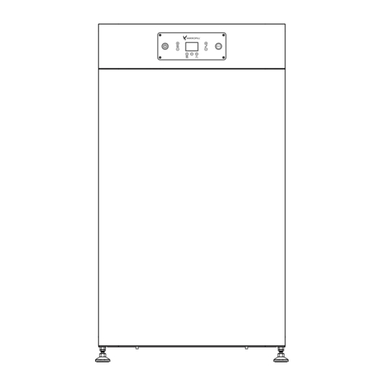
Page 5: Dimensions
Data may deviate slightly due to fabrication tolerances. • We reserve the right to make changes without prior notification. ▲ FIGURE 01. DIMENSIONS OF THE ETHOS FLOOR STANDING BOILERS. ETHOS 350 ETHOS 550 1” 1” Ø 32 Ø 32 1½”... -
Page 6: Safety Guidelines
SA FE T Y G UI D EL I N E S CONDITIONS Mikrofill Systems Ltd. shall not be liable for any damages caused by non-compliance with this manuals instructions. Only original parts must be used for service purposes. GENERAL GUIDELINES... -
Page 7: Service
03452 60 60 20. GENERAL RESTRICTIONS Mikrofill products should always be used, installed and maintained in accordance with the statutory requirements, specifications and standards applicable to these installations. Mikrofill cannot be held responsible for any losses or damage whether direct or consequential that have arisen as a result of incorrect or poor installation. -
Page 8: Description
DESC RI P T I O N GENERAL The Mikrofill ETHOS floor standing boilers are environmentally friendly gas fired heating boilers with a modulation range between approximately 10% and 100% of their maximum output. The appliances have low and CO emission, which satisfies the most stringent environmental requirements. -
Page 9: Main Components
D ESC RIPTIO N FRONT VIEW: REAR VIEW: TOP VIEW: MAIN COMPONENTS: Burner #00 Control Unit Burner #01 Control Unit Combustion Fan Control Fascia Electrical Connections Gas Valve Heat Exchanger and Burner Package Flap Valve Venturi REAR CONNECTIONS: Condense Outlet Flow Connection Gas Connection Pressure Relief Valve Outlet... -
Page 10: Boiler Control
DESC RI P T I O N BOILER CONTROL If there is a heat demand, and if all necessary conditions have been fulfilled and all safety devices are satisfied, the boiler will start. This heat requirement will arise if: • the flow temperature of the boiler is less than the required flow temperature. •... -
Page 11: Delivery & Transport
D EL I VERY & T RAN SPO R T DELIVERY The boiler is delivered fully assembled, tested and packed. • Check the boiler for damage upon receipt. • Check whether the items delivered are correct and in accordance with the items ordered. TRANSPORT The packing should only be removed after transportation. -
Page 12: Installation
INS TAL LA TI O N REGULATIONS The appliance should be installed by a competent installer in accordance with the applicable national and local standards, rules and regulations (please refer to pages 06 and 07 for safety guidelines). INSTALLATION GUIDELINES The following guidelines should be complied with;... -
Page 13: Ventilation
IN ST AL LA TION VENTILATION The ventilation of the installation room should conform to current gas regulations. GAS CONNECTION The gas connection is located on the rear of the appliance (see page 09). It should be installed by a competent installer in accordance with the applicable national standards. -
Page 14: Internal Controls Breakdown (Main Pcb)
INS TAL LA TI O N INTERNAL CONTROLS BREAKDOWN (MAIN PCB) 01 02 03 01 02 03 04 05 01 02 04 05 06 06 07 08 09 10 03 04 ▲ FIGURE 02. TOP VIEW OF MAIN PCB. • X00 Pin 01: Power to Main PCB •... -
Page 15: Internal Controls Breakdown (Control Fascia)
IN ST AL LA TION INTERNAL CONTROLS BREAKDOWN (CONTROL FASCIA) ▲ FIGURE 03. TOP VIEW OF CONTROL FASCIA. • X01 Pin 01: Control Fascia to Main PCB • X03 Pin 02: Communication with Master • X05 Pin 01: Alarm Output •... -
Page 16: Controls And Options
INS TAL LA TI O N CONTROLS AND OPTIONS The boiler features an automatic fully modulating control system and as such can be used as a ‘stand alone’ appliance. The standard controls include; • 0 - 10 V Input ready. •... -
Page 17: Flue Connection
/ inspection (GasSafe TB 008 Ed. 2.1). A direct connection to a brick chimney is not permissible unless a suitable liner is installed. The following table gives the flue gas data for all types: ETHOS 350 ETHOS 550 Average Flue Gas Temperature at Full Load °C... -
Page 18: Flue Length
• the flue system and outlet. There is a maximum over pressure of around 2.0 mbar (200 Pa) for the ETHOS 350 and 2.5 mbar (250 Pa) for the ETHOS 550 in the boiler for the flue gas discharge system. -
Page 19: Condense Connections
25°K at full load). The minimum required water circulation should not be adversely affected by the use of valves, non-return valves, systems in which several boilers are connected to a common distribution pipe etc. The maximum water flow is achieved at ΔT 15°K. ETHOS 350 ETHOS 550 ΔT 20°K Nominal Flow Rate (Q) 14.99... -
Page 20: Shut-Off Valves
INS TAL LA TI O N SHUT-OFF VALVES It is recommended that manual valves should be installed between the flow and return connections to the installation. VALVES (BOILERS IN CASCADE ARRANGEMENT) To prevent water flow through non-firing boilers, and hence unnecessary heat loss, a spring loaded non-return valve may be installed on the return pipework external to the boiler. -
Page 21: Water Pressure
IN ST AL LA TION WATER PRESSURE At a maximum flow temperature of 90°C and with the nominal water flow that occurs at a ΔT of 20°K, the minimum operating pressure should be at least 1.5 bar. The operating pressure should be measured when the external pump is switched off. -
Page 22: Water Hardness
INS TAL LA TI O N WATER HARDNESS Water hardness levels are caused by dissolved minerals in the water and will vary geographically. The harder the water, the more likely that problems with precipitation (limescale deposits) will occur, causing permanent damage to the boiler and associated equipment. -
Page 23: Boiler Module
OP ER A TING INST RU C TIONS BOILER MODULE RESET RESET DHW Selection Heating Selection Multi-Function Reset Switch DHW Temperature Heating Temperature Power Switch PCB SYMBOL KEY - OpenTherm Connection - Heating Circuit Active - Information - Summer Mode - Wireless - Pump Active - Reset Required... -
Page 24: Switching On The Appliance
O P E RAT I NG I N ST R UC T I ON S WARNING: • The appliance should be installed by a competent installer. • These operating instructions should be closely followed. • If the cause of any fault cannot be determined, please contact the technical department. •... -
Page 25: Information Display
OP ER A TING INST RU C TIONS INFORMATION DISPLAY: RESET RESET DHW OPERATION • DHW Mode can be enabled or disabled by using the button. • The DHW setpoint can be increased or decreased by using the buttons. HEATING OPERATION •... -
Page 26: History Mode
O P E RAT I NG I N ST R UC T I ON S HISTORY MODE • To access history mode, press and hold until the display shows ‘Bu 0’. • Press the button and the display will flash ‘Hi 0’. •... -
Page 27: Possible Error Codes Continued
OP ER A TING INST RU C TIONS POSSIBLE ERROR CODES continued. ERROR CODE DESCRIPTION RESOLUTION Return temperature sensor short The return temperature sensor is registering a short circuit. Check the circuit. connection to the sensor and replace the sensor if necessary. Return temperature sensor open The return temperature sensor is registering an open circuit. -
Page 28: Commissioning
Start the boiler. Allow the boiler to run and stabilise (around three minutes). At full load, the following settings should be checked and corrected if necessary: REFERENCE VALUE FOR MAXIMUM LOAD Reference value for CO 8.4% ± 0.2 ETHOS 350 - 550 (natural gas) 9.5% ± 0.2 ETHOS 350 (natural gas) 8.5% ±... -
Page 29: Maximum Load Adjustment
C OM MISS IONING MAXIMUM LOAD ADJUSTMENT Press and hold the button for three seconds until the below display appears, the boiler will then start to operate at minimum load. To adjust to maximum rate, press and hold until the below display appears, the boiler will then start to operate at maximum load. -
Page 30: Setting The Co Value For The Ethos Range
CO M M I S S I ON I N G SETTING THE CO VALUE FOR THE ETHOS RANGE • Any adjustments should only be carried out by competent persons. • After adjustment of the gas valve the adjusters must be resealed. There is a setting screw on the gas valve with which the CO value can be set at maximum load. -
Page 31: Conversion From Natural Gas To Propane
C OM MISS IONING CONVERSION FROM NATURAL GAS TO PROPANE For natural gas to propane conversion, it is only necessary to change the gas volume by altering the CO values as described on pages 28 - 30. C A SC A DE S ET- U P AUTO DETECTION MODE Cascade structure will need to be auto detected prior to cascading the boilers. -
Page 32: Cascade Test Mode
CA S C A DE S E T - UP CASCADE TEST MODE • Press and hold the buttons together for three seconds. • This will send a request to the master boiler to fire all slave boilers. • This can be increased to 100% by pressing the button until the display below is shown. -
Page 33: Maintenance
Check the water system is correctly filled and free of air. Air in the boiler could cause damage to the heat exchanger. For this reason, the automatic air vent in the ETHOS 350 and 550 must be left open. •... -
Page 34: Removal Of Gas Valve And Venturi
M AI N T EN A N C E REMOVAL OF GAS VALVE AND VENTURI • Isolate the gas and electrical supplies to the boiler. • Remove the four screws from the flange on the rear of the gas valve ( •... -
Page 35: Removal Of Fan And Burner Assembly
MA INT ENA NCE REMOVAL OF FAN AND BURNER ASSEMBLY • Isolate the gas and electrical supplies to the boiler. • Remove the caps from the ignition electrode and ionisation probe. • Remove the two electrical connections from the fan. •... -
Page 36: Setting / Checking Of Electrode And Probe Gaps
M AI N T EN A N C E SETTING / CHECKING OF IGNITION ELECTRODE AND IONISATION PROBE GAPS In addition to the annual maintenance, please ensure the following is carried out: • Isolate the gas and electrical supplies to the boiler. •... -
Page 37: Component List
C OM PON ENT L IS T Any components within the ETHOS 350 - 550 that may require replacing have been listed in this section, along with their respective part codes. If any part needs replacing which is not listed here, please contact our technical department on 03452 60 60 20 for assistance. -
Page 38: Core Components
CO M P O NE N T L I S T CORE COMPONENTS 38 TEC HN ICAL DOCUM ENTA TION... -
Page 39: Conversion Formulae & Factors
C O N V E R S I ON FORM UL A E & FA C TO R S FORMULAE 20.9 - measured O measured CO x 20.9 x 11.7 = 20.9 - 20.9 11.7 11.7% CO is the maximum CO percentage that is generated by stoichiometric burning of G20 natural gas (H-gas). - Page 40 CO N VE RS I ON F O R M U L A E & F A CT ORS FOR NON-CONDENSING BOILERS: 0.339 0.377 nb = 90 - + 0.008 x ΔT no = 100 - + 0.009 x ΔT FOR CONDENSING BOILERS: As a result of condensation, the efficiency at the lower value increases.
-
Page 41: Notes
N OTE S TECHNICAL DOCUME NTATION 41... - Page 42 NOT ES 42 TEC HN ICAL DOCUM ENTA TION...
- Page 43 ISO 9001 Registered Quality Management...
- Page 44 Mikrofill Systems Ltd. 11 Merse Road, North Moons Moat, Redditch, Worcestershire B98 9HL , U K +44 (0)3452 60 60 20 +44 (0)3452 60 60 21 info@mikrofill.com www.mikrofill.com...
Need help?
Do you have a question about the ETHOS 350 and is the answer not in the manual?
Questions and answers