Table of Contents
Advertisement
Quick Links
Advertisement
Table of Contents

Subscribe to Our Youtube Channel
Related Manuals for PSV groupe DRC-C10


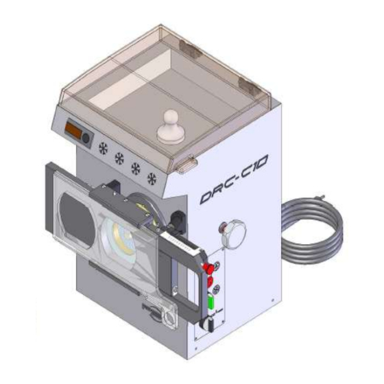
Summary of Contents for PSV groupe DRC-C10
- Page 1 Usine du berre au Loup – RD147 – BP20 – 95420 Genainville – France Brand, patents and models registered in France and abroad R.C.S. Pontoise B 642 033443...
- Page 2 2. BT 2014 / 35 / UE 3. MACHINE 2006 / 42 / CE CERTIFICATE OF COMPLIANCE rules of the European Community. The Manufacturer hereby PSV Groupe, BP20 95420 Genainville certifies that the new material designated below: REFRIGERATED MINCER TYPE : ………….
-
Page 3: Table Of Contents
TABLE OF CONTENTS 1 / INTRODUCTION AND STANDARDS -------------------------------------------- p.4 2 / INSTALLATION AND ELECTRICAL CONNECTION ------------------------- p.5 3 / FEATURES AND SPECIFICATIONS --------------------------------------------- p.6 4 / DESCRIPTION ------------------------------------------------------------------------- p.8 A / INSTALLING THE BODY ------------------------------------------------------------------------------ p.8 B / MOUNTING PLATES AND KNIVES --------------------------------------------------------------- p.9 5 / MAINTENANCE. - Page 4 1/ INTRODUCTION DRC H12 mincer can mincer all kinds of meat for the production of hamburgers, meatballs, sausage, etc..It has Three cutting elements version UNGER 82 (2 plates and double cutting knife). STANDARDS These devices meet the requirements of the decrees and safety standards.
- Page 5 2/ INSTALLATION Position the machine on a stable and solid work surface. See recommended height of sketches above. ELECTRICAL CONNECTION The electrical connection must be performed by qualified personnel and be conducted in compliance with safety standards in force.
- Page 6 The line of the power supply must be carried out using a cable section adapted to the power of the machine and must include two phase conductors and a grounding conductor (voltage machine 230v, 50 Hz) . The power of the machine must be protected by a breaker. ...
- Page 7 3/ FEATURES TECHNICAL SHEET DRC – C10 Specifications DRC – C10 396,5 x 330 x 504 Dimensions (mm) 52kg Weight 655x460x705 Packing (mm) 300 kg/h Théoritical flom 1,5CV / 1,12 KW continu Engine TRI - 400v - 50 HZ / Voltage MONO - 230V - 50HZ Gear Box...
-
Page 8: Description
1 double knife, 1 cutting plate, 1 Standard equipment plateØ3 R134A 4/ DESCRIPTION A / INSTALLING THE BODY Present the body in front of the machine. Fit the body in its seat . Tighten the nut until red ring can not been seen anymore. -
Page 9: B / Mounting Plates And Knives
Be sure body is well tighten B / MOUNTING PLATES AND KNIVES SYSTEM WITH 3 CUTTING ELEMENTS (UNGER). Disconnect the machine from the electricity grid for the NOTE following: Insert the A-helix (2) inside the body (1) with a slight twisting motion for a good engagement with the hex output shaft engine. - Page 10 Installation should be done as described above in several phases. 2/ PRECAUTIONS FOR INSTALLATION AND MAINTENANCE SYSTEM UNGER Make sure that the cutting system is mounted exactly as shown below. Improper installation, including upside down, causing breakage of the blades or plates.
-
Page 11: Maintenance
C/ STARTING Initialize coolign system 15 minutes before first mincing of the day (settings of temperatures). Cooling system must always be on, even for non-continuous mincing. NF EN 12331+A2 2010-07 information reagrding temperature having to be below 7°C inside the whole way for meat from tray to cuting system. -
Page 12: B / Preliminary Cleaning
maintenance, disassembled, cleaned and disinfected after each half day of work. To do so, we recommend to use detergent (like dish soap or ammonia products). Preliminary cleaning: Remove visible dirt by brushing (body, propeller, screw, plates and knives). DISINFECTION Immerse all removable parts in a bath of warm water (Temperature 45-55 ° C.) with a detergent-disinfectant appropriate. -
Page 13: Accessories
plate of hash, as the knife rotates in contact with it. When the holes have a diameter less than 4mm, the risk of introduction of the fingers does not exist (CF NF E 09-010). It is the same for diameters between 4 and 8mm included, provided that the plate has a thickness of 5mm. - Page 14 10/ INSTALLATION OF STEAK RECONSTITUOR (OPTIONAL) Place support A on mincer nut and lock it with fork 7 and with button 8. Place the body of B. Slide the C plate inside the ray of the support.
-
Page 15: 11/ Using The Steak Reconstituor
11/ USING OF STEAK RECONSTITUOR 1/ Sélect reconstituor mode on control board, pages (31/32). 2/ push sélector to set weight. 3/ push against the body. - Page 16 4/ Press button to start mincing and form steack 5/ mincing stops automatically and burger can be realised by pulling the device to the right.
- Page 17 Using reconstituor in bulk mode : Pull the plexi plate to the right. Place the mouth in front of the plate of mincer so the met can go out continously EXPLODED AND NOMENCLATURE HACHOIR – DRC-C10...
- Page 18 12/ EXPLODED VIEW OF RECONSTITUOR...
- Page 19 Burger forming device spare parts SCHEME DESCRIPTIONS QUANTITY PART NET PRICE € NUMBER BODY SCREW SUPPORT TIROIR 1018 PIECE 1 SUPPORT 1019 TIROIR PIECE 2 SUPPORT 1020 TIROIR VIS TF ZVIS062 AXE DE POIGNEE FOURCHETTE BOUTON DE SERRAGE CHASSIS TIROIR 1021 AXE GUIDAGE DEMI 1 // 2...
- Page 20 13/ EXPLODED MINCER DRC-C10...
- Page 21 14/ NOMENCLATURE NOMENCLATURE MINCER DRC-C10 PRICE Désignation REPERE Réf - PSV € Carrosserie 1057 Casquette 1057 Carter arrière 1057 Socle 1057 Plateau 1057 Guide support boitier électrique 1057 Butée du boitier électrique 1057 Support boitier électrique 1057 Support ventilateur condenseur...
- Page 22 Poignée de serrage inox 60x30 1013 Capot Lexan bronze 1050 Charnière à friction Poignée Corps Hélice X1053 Plaque couteau H82/00 36.7 Couteau CTX H82 Plaque H82/3MM 30.60 Bague Écrou de corps Pilon Bouton double touche lumineux Bloc auxiliaire 1 LED 24V 1NO 1NF 1042 Bouton tournant 3 positions (reconstitueur vrac) 1043...
- Page 23 15/ EXPLODED GEAR BOX DRC-C10 (Detail B)
-
Page 24: 16/ Exploded View Body
16/ EXPLODED BODY (Détail A) 17/ EXPLODED VIEW CONTROL... - Page 25 VERSION WITH RECONSTITUOR (Detail C) 18/ CONTROL DRC-C10...
- Page 26 Control DRC- C10 without reconstituor. PANEL OF CONTROL ON / OFF for cutting system ON / OFF for cooling system burger reconstituor mode / continous...
- Page 27 Control DRC- C10 with reconstituor. PANEL OF CONTROL ON / OFF for cutting system ON / OFF for cooling system burger reconstituor mode / continous...
- Page 28 MODE BULK Button on right position (light on). start cutting system (Green) On. (Red) Stop. MODE WITH RECONSTITUOR Button on left position (light off). Reconsituor is launching and stopping automatically the cutting system on / off button is inoperant...
- Page 29 19/ ELECTRICAL SCHEME DRC-C10 WITH RECONSTITUOR...
- Page 30 20/ INSTALLING AND DISMANTLING OF THERMOSTAMETRE 1/ Push A to delock the brake, and slide backward until total extraction (2). 3/ Pull thermostametre outside. PLUG THERMOSTAMETRE...
- Page 31 SETTINGS THERMOSTAMETRE To check or modify settings, push button , SET is appearing, push on3 and is appearing push on or on to modify value. Push on to validate. Check settings : Push 5 secondes on button SHy is appearing Push on button 1 is appearing Push on button...
Need help?
Do you have a question about the DRC-C10 and is the answer not in the manual?
Questions and answers