Table of Contents
Advertisement
Quick Links
F
L
O
O
F
L
O
O
Usine du berre au Loup – RD147 – BP20 – 95420 Genainville – France
Marques, brevets et modèles déposés France et étranger. R.C.S. Pontoise B 642 033443
R
S
T
A
R
S
T
A
D
D
U
s
e
U
s
e
« Original manual »
N
D
I
N
N
D
I
N
R
C
1
1
R
C
1
1
r
G
u
r
G
u
1
G
M
I
N
G
M
I
N
4
4
i
d
e
i
d
e
C
E
R
C
E
R
Advertisement
Table of Contents

Related Manuals for PSV groupe DRC114


Summary of Contents for PSV groupe DRC114
- Page 1 Usine du berre au Loup – RD147 – BP20 – 95420 Genainville – France Marques, brevets et modèles déposés France et étranger. R.C.S. Pontoise B 642 033443 « Original manual »...
- Page 2 Certificate of Conformity to rules of the European Community The manufacturer hereby GROUPE PSV, BP20 95420 GENAINVILLE NEW EQUIPMENT COVERED BY FOLLOWING DIRECTIVES MACHINE 2006 / 42 / CE CEM 2014 / 30 /UE BT 2014 / 35 / UE MODELE : TRADITIONAL MINCER TYPE : DRC114CS SERIAL NUMBER :...
-
Page 3: Table Of Contents
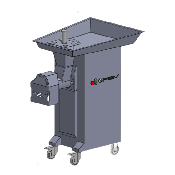
TABLE OF CONTENTS 1/ INTRODUCTION AND NORMALISATION ………………… p.4 2/ INSTALLATION AND ELECTRICAL CONNECTION …… 3/ CHARACTERISTICS AND TECHNICAL SHEET………. 4/ DESCRIPTION ……………………………………………... A/ INSTALLING THE BODY ………………………………… p.8 B/ PLATES AND KNIVES MOUNTING ………..……… 2/ SYSTEM WITH 3 CUTTING ELEMENTS……………… p.10 3/ SYSTEM WITH 5 CUTTING ELEMENTS……………. - Page 4 1/ INTRODUCTION The mincer DRC 114 can mince all kinds of meat for the production of hamburgers, meatballs, sausage… The mincer can be equipped with 3 or 5 cutting elements UNGER. (See on page 10/11) The mincer 114 is equipped of one or two knife double side with removable blades. NORMALISATION These devices meet the requirements of the decrees and safety standards.
- Page 5 2/ INSTALLATION Place the machine on a stable and solid floor ELECTRICAL CONNECTION Electrical plug in must be preformed by qualified personnel and be conduced in compliance with safety standards. The line of the power supply must be carried out using a cable section adapted to the power of the machine and must include three phase conductors and a grounding conductor (voltage machine 400v, 50 Hz) or two phase conductors and a grounding conductor (voltage machine 230v, 50 Hz) .
- Page 6 3/ CHARACTERISTICS TECHNICAL SHEET DRC 114 TECHNICAL CHARACTERISTICS DRC 114 1000 x 760 x 1250 Dimensions 129 kg Weight 1200 X 800 X 1350 Packing dimensions 900 Kg/h Débit théorique Motor 5,5 CV / 4,1 KW 3 PHASES - 400v - 50 HZ Tension PSV gear box Gear box...
-
Page 7: 4/ Description
4/ DESCRIPTION A/ BODY MOUNTING Rotate the safety guard to place the body Place the body in front of the machine... - Page 8 Fit the body in its seats (two blots through).
- Page 9 Tighten the two clamp handles setting the body on the machine Make sure that the body is properly applied against the front...
- Page 10 B/ MOUNTING PLATES AND KNIVES 1/ 3 CUTTING ELEMENTS SYSTEM (UNGER). NOTE : DISCONNECT THE MACHINE OF THE ELECTRICAL RETE FOR THE FOLLOWING OPERATIONS : A- Insert the helix (2) inside the body (1) with a slight twisting motion for a good engagement with the hex output shaft engine.
- Page 11 5 ELEMENTS CUTTING SYSTEM (UNGER). NOTE : DISCONNECT THE MACHINE OF THE ELECTRICAL RETE FOR THE FOLLOWING OPERATIONS : A- insert the helix (2) inside the body (1) with a slight twisting motion for a good engagement with the hex output shaft engine. B- mount the plate/knife (3).
-
Page 12: C/ Precautions
C/ PRECAUTIONS 1/ PRECAUTIONS FOR THE MOUNTING AND MAINTENANCE OF UNGER SYSTEM Make sure that the system is mounted as shown below. Improper installation, including upside down, causes breakage of plates and knives. The plate knife must be perfectly aginst the face of the body. The nut stainless steel machine should not be tightened significantly. - Page 13 2/ USING THE PANEL ON BUTTON REVERT EMERGENCY BUTTON STOP OFF BUTTON Pushing the GREEN button, the machine starts. The rotation of the feed screw must be done in unclock sense. The machine stops by pushing the button. ...
- Page 14 3/ USING THE PLASTIC FEEDER The machine is delivered with a plastic feeder to push the meet in the feed screw. Using the plastic feeder is extremely important, it is strictly forbidden to us the hand to avoid any failures.
-
Page 15: 5/ Maintenance
5/ MAINTENANCE DISCONNECT BEFORE ANY INTERVENTION A/ CLEANING OF THE MACHINE : For obvious hygiene reasons, the machines for mince meat need to be cleaned often and correctly. Machines must be maintained in perfect conditions, cleaned, dismounted, disinfected two times per day. For cutting elements cleaning, it is necessary to dismount the whole body/helix and the cutting element in the same time to avoid any failures (and following the standard NF EN 12331:2013). -
Page 16: E/ Maintenance
Do not immerse the device Do not clean with high pressure jet The brushes used must be cleaned with a detergent solution. The chopper’s body does not require special maintenance. Just use a towel or disposable paper moistened Avoid using abrasive cleaners that will damage the steel. -
Page 17: 6/ Warning
6/ WARNING SECURITY PARTS : En aucun cas la plaque protège-main située sur le plateau doit être déformée et à fortiori enlevée ou dessoudée. PROTECTION AGAINST THE RISKS OF FAILURES CAUSED BY KNIVES : There is a serious risk when the operator can move the fingers through the plates as the knife rotates in contact with it. -
Page 18: 9/ Warranty Conditions
9/ WARRANTY CONDITIONS En tant que fabricant, nous garantissons notre matériel un an contre tout vice de fabrication, la facture faisant office de bon de garantie. As a manufacturer, we guarantee one year for any manufacturing defect, the invoice acting as a warranty. IMPORTANT : Electricals and electronics are excluded from the warranty. - Page 19 10/ NOMENCLATURE NOMENCLATURE DRC 114 - PART DESCRIPTIONS REFERENCE QTY / 114 NUMBER PLASTIC FEEDER 921C STAINLESS STEEL PLATE + HAND PROTECT STAINLESS STEEL NUT COMPENSATION RING PLATE 114 D114/5MM KNIFE 114 CTX_D114 PLATE / KNIFE 114 D114/00 KNIFE HOLDER 114 STAINLESS STEEL FEED SCREW114 CLAVETTE PLAQUE DE COUPE VIS TFB FIXATION CLAVETTE...
- Page 20 VIS THEF FIXATION REDUCTEUR ZVIS007 HEXAGONAL NUT ZVIS025 GEAR FIXATION SCREW ZVIS919 ION/OFF BUTTON + AUXILIARY BLOCK 459-2/459-1 ON/OFF BUTTON + CAP + AUXILIARY BLOCK 936/936A/937B BOUTON IMPULSION ARRIERE + CAP + AUXILIARY BLOCK 937D/935B/93C INSERT TETE CYLINDRIQUE VIT020 RONDELLE PLATE ZVIS047 RONDELLE EVENTAIL EXTERIEUR ZVIS060...
- Page 21 11/ EXPLODED VIEW...
-
Page 25: 12/ Electrical Scheme
12/ ELECTRICAL SCHEME... - Page 26 14 NOTES : ……………………………………………………………………………………… ……………………………………………………………………………………… ……………………………………………………………………………………… ……………………………………………………………………………………… ……………………………………………………………………………………… ……………………………………………………………………………………… ……………………………………………………………………………………… ……………………………………………………………………………………… ……………………………………………………………………………………… ……………………………………………………………………………………… ……………………………………………………………………………………… ……………………………………………………………………………………… ……………………………………………………………………………………… ……………………………………………………………………………………… ……………………………………………………………………………………… ……………………………………………………………………………………… ……………………………………………………………………………………… ……………………………………………………………………………………… ……………………………………………………………………………………… ……………………………………………………………………………………… ……………………………………………………………………………………… ……………………………………………………………………………………… ……………………………………………………………………………………… ……………………………………………………………………………………… ……………………………………………………………………………………… ……………………………………………………………………………………… ……………………………………………………………………………………… ……………………………………………………………………………………… ……………………………………………………………………………………… ……………………………………………………………………………………… ……………………………………………………………………………………… ……………………………………………………………………………………… ………………………………………………………………………………………...
- Page 27 DISTRIBUTOR STAMP...
Need help?
Do you have a question about the DRC114 and is the answer not in the manual?
Questions and answers