
Subscribe to Our Youtube Channel
Related Manuals for L3 Aviation Products Lynx NGT-9000+


Summary of Contents for L3 Aviation Products Lynx NGT-9000+
- Page 1 APPENDIX E - Pilot's Guide Pilot’s Guide for Models NGT-9000 NGT-9000R NGT-9000+ NGT-9000R+ NGT-9000D NGT-9000RD Aviation Products Rev.4/07-13-2016...
- Page 2 Document Precedence This Pilot’s Guide provides general information about the operation of the NGT-9000. Refer to your FAA-approved Airplane Flight Manual (AFM) and its flight manual supplements for information specific to your aircraft. If there is conflicting information between the AFM and this guide, the AFM takes precedence over this guide.
- Page 3 Pilot’s Guide Methods and apparatus disclosed and described herein have been developed solely on company funds. No government or other contractual support or relationship whatsoever has existed which in any way affects or mitigates proprietary rights of ACSS in these ®...
-
Page 4: Table Of Contents
Table of Contents Chapter 1: Description INTRODUCTION ..................1-1 SPECIFICATIONS ................1-2 / 1-3 Pilot Advisory ....................1-4 Functional Description .................1-5 Options ....................1-6 ADS-B ....................1-6 ADS-R ....................1-7 TIS-B System Capabilities ..............1-8 Traffic Awareness System ..............1-10 FIS-B System Capabilities ..............1-11 Equipment Description ................1-14 Standard Equipment ................1-14 Optional Equipment ...................1-14 GPS Antenna and Internal GPS Receiver ...........1-14... - Page 5 Table of Contents (continued) Squawk VFR Button ................2-11 MSG Button ..................2-11 On-GND Indicator ................2-11 System Test Button ................2-11 Traffic Operation ..................2-13 Traffic Screen ..................2-13 Ownship Symbol .................2-14 Traffic Symbols ..................2-14 Traffic Display Priority ................2-15 Zoom Buttons ..................2-15 Range Rings ..................2-17 Traffic Altitude Mode ................2-17 TFC Button ..................2-18...
- Page 6 Table of Contents (continued) Weather Map Legend Screen ............2-30 Banner ..................2-30 Display Area ................2-32 Declutter Option Screen.............2-32 Weather Map Text Screen ............. 2-33 Display Area ................2-33 Banner ..................2-33 Product Select List Window ............2-34 FIS-B Graphic Winds & Temp Application ...........2-34 Traffic Button .................
- Page 7 Table of Contents (continued) WiFi Interface ..................3-3 Aural Announcements .................3-3 Extended Audio Callouts ................3-4 Audio Inhibit ....................3-4 CP-2500 Control Panel................3-4 Power On/off ..................3-5 Normal Operation ..................3-6 Chapter 4 Principles of TAS Operation Introduction ....................4-1 Sensitivity Levels ..................4-1 Sensitivity Level A ................. 4-1 Sensitivity Level B .................
- Page 8 List of Illustrations Figure 1-1: Example Of Panel Mount Lynx NGT-9000 .......1-2 Figure 1-2: Example Of Remote Mount Lynx NGT-9000 ......1-5 Figure 1-3: Example Of Own Aircraft UAT, 1090ES & TAS Traffic ....1-9 Figure 2-1: Example Of Splash Screen ............2-2 Figure 2-2: Example Of System Status / Version Screens ......2-3 Figure 2-3: Example Of Flight Id Screen .............2-4 Figure 2-4: Example Of Normal Operation ..........2-4...
- Page 9 List Of Abbreviations and Acronyms ° Degree Advisory Circular Above ADS-B Automatic Dependant Surveillance – Broadcast ADS-R Automatic Dependant Surveillance – Rebroadcast Airplane Flight Manual Above Ground Level AIRMET Airmen’s Meteorological Information Altitude Air Traffic Control ATCRBS Air Traffic Control Radar Beacon System Below Brightness CDTI...
- Page 10 List Of Abbreviations And Acronyms (cont.) Message Multilink Surveillance System NACp Navigation Accuracy Category for Position Non Altitude Reporting National Airspace System NEXRAD Regional and Next-Generation Radar Navigation Integrity Category NOTAM Notices to Airmen NM or nmi Nautical Miles Normal Other Traffic Proximity Advisory PALT...
-
Page 11: Chapter 1: Description
Lynx NGT-9000 Description ® CHAPTER 1 DESCRIPTION INTRODUCTION The Lynx NGT-9000 family of products are a Mode S Level 2 dens Class 1 Transponder with an integrated GPS receiver providing Automatic Dependent Surveillance-Broadcast (ADS-B) output using 1090ES (Extended Squitter). The Lynx NGT-9000 also receive ADS-B data via 1090ES and UAT (978 MHz Universal Access Transceiver). -
Page 12: Specifications
Description Lynx NGT-9000 ® SPECIFICATIONS Part Number: 9029000-20000 (panel mount) Weight: 2.96 Lbs. Power +14.0 VDC nominal or +28.0 VDC nominal. Requirements: 19.0 watts nominal, 24.0 watts maximum Display Range 0.05 fl to 150 fl Luminance: Start Up Time On Ground 20 seconds or less In air 5 seconds or less. - Page 13 Lynx NGT-9000 Description ® SPECIFICATIONS Part Number: 9029000-40000 (remote mount) Weight: 2.75 Lbs. Power +14.0 VDC nominal or +28.0 VDC nominal. Requirements: 17.0 watts nominal, 24.0 watts maximum Start Up Time On Ground 20 seconds or less In air 5 seconds or less. Interfaces: ARINC 429, RS-422, RS-232, Discrete In- put/Outputs, RF Suppression Bus, and DCM...
-
Page 14: Pilot Advisory
Description Lynx NGT-9000 ® PILOT ADvISORy The display of ADS-B data only supplements and does not replace any operational procedure. All pilots/operators are reminded that the airborne equipment that displays traffic is only for pilot situational awareness. This equipment is not approved as a collision avoidance tool and does NOT relieve the pilot of responsibility to “see-and-avoid”... -
Page 15: Functional Description
Lynx NGT-9000 Description ® FUNCTIONAL DESCRIPTION The panel mount versions of the Lynx NGT-9000 can display and control the following information: • Flight ID or aircraft Tail Number • Transponder (MODE S) and Traffic Mode of Operation • Derived Altitude Data •... -
Page 16: Options
Description Lynx NGT-9000 ® The unit provides the transponder code, reply symbol and mode of operation to the display. The Lynx NGT-9000 provides own aircraft data via ADS-B Out capabilities. The ADS-B In capabilities include Basic Airborne Situational Awareness (AIRB) and Enhanced Visual Acquisition (EVAcq) traffic information that improves situational awareness and flight safety by providing aircraft position, velocity, and heading information that is automatically transmitted to other aircraft and... - Page 17 Lynx NGT-9000 Description ® • The traffic display shows the relative position of ADS-B or standard traffic using text, shapes, and colors. ADS-B also provides similar information on ADS-B equipped ground vehicles. • The effective surveillance range is 60 nmi (ADS-B In) The passive-mode surveillance range is 160 nmi and maintains report messages for a minimum of 200 1090ES ADS-B participants and 300 UAT ADS-B participants simultaneously.
- Page 18 Description Lynx NGT-9000 ® Traffic Information Service - Broadcast (TIS-B) TIS-B is the broadcast from Ground Radio Stations of ATC-derived traffic information to ADS-B equipped aircraft. • The actual availability of services depends upon the availability of ground-based radar to support TIS-B source data. •...
-
Page 19: Ads-R
Lynx NGT-9000 Description ® 70 nm ( Other Aircraft 1090ES 30 nm ( TIS-B ADS-R Other Aircraft Own Aircraft 1090ES TAS (model option) ADS-R Other Aircraft TIS-B FIS-B Other Aircraft UAT Non-Equipped Mode A/C Equipped TIS-B ATC - Ground Station Figure 1-3: Example of Own Aircraft UAT, 1090ES, &... -
Page 20: Traffic Awareness System
Description Lynx NGT-9000 ® Traffic Awareness System (TAS) The TAS option is available with model NGT-9000+ and NGT- 9000R+. TAS is an active system that operates as an aircraft-to- aircraft interrogation device. The unit interrogates transponders in the surrounding airspace similar to ground based radar; with an effective active-mode surveillance range of 35 nmi. - Page 21 Lynx NGT-9000 Description ® Flight Information Service - Broadcast (FIS-B) FIS−B is a ground broadcast service provided through the ADS−B Services network over the 978 MHz UAT data link. The FAA FIS−B system provides pilots and flight crews of properly equipped aircraft with a cockpit display of certain aviation weather and aeronautical information.
-
Page 22: Table 1-2: Description Of Fis-B Available Information
Description Lynx NGT-9000 ® Table 1-2: Description of FIS-B Available Information Product deScriPtion AIRMET Text/graphical report - Airmen’s Meteorological Infor- mation is a weather advisory issued by a meteoro- logical watch office a potentially hazardous condition exists for low-level aircraft and/or aircraft with limited capability. - Page 23 Lynx NGT-9000 Description ® Table 1-2: Description of FIS-B Available Information (continued) Product deScriPtion SIGMET, Text/graphical report - hazardous thunderstorms Convective and related phenomena across Continental US. Convective SIGMETs issued for thunderstorms and related phenomena do not include with thun- derstorms such as turbulence, icing, low level wind shear and IFR conditions Text report - Terminal Aerodrome Forecast is a format...
-
Page 24: Equipment Description
Description Lynx NGT-9000 ® EqUIPMENT DESCRIPTION The Lynx NGT-9000 MSS family consists of the following standard and optional equipment. Refer to the Aircraft Flight Manual Supplement to determine what optional equipment is installed. Chapter 3 provides a list of optional cockpit switches and lamps. Required Equipment •... -
Page 25: Directional Antenna
Lynx NGT-9000 Description ® Directional Antenna A directional antenna is used to receive 1090MHz and transmit 1030MHz for models with TAS. Alternate Displays Screen information may look different on displays interfaced with the Lynx NGT-9000. Refer to that display’s manual for a description of how information is depicted. - Page 26 Description Lynx NGT-9000 ® Page intentionally blank 1-16 Pilot’s Guide...
-
Page 27: Chapter 2: Operation
Lynx NGT-9000 Operation ® CHAPTER 2 OPERATION INTRODUCTION This chapter describes preflight procedures for the panel and remote mount Lynx NGT-9000. Operational information in this chapter is specific to the panel mount Lynx NGT-9000. Refer to Chapter 3 (Controls and Indicators) for operation information for installations with a CP-2500 Control Panel or compatible display. -
Page 28: Normal Operation (Remote Mount)
Operation Lynx NGT-9000 ® NORMAL OPERATION (REMOTE MOUNT) Operational control of the remote mount version of the Lynx NGT- 9000 is accomplished with a CP-2500 Control Panel. An ADS-B Out Fail lamp (if installed) provides ADS-B output status of the Lynx NGT- 9000. -
Page 29: System Status / Versions Screen
Lynx NGT-9000 Operation ® System Status / Versions Screen The system status is shown on the left screen and should show “System Pass” in green text. The version screen is located on the right side and shows the software and database version information. See Figure 2-2. -
Page 30: Flight Id Screen (Optional)
Operation Lynx NGT-9000 ® Flight ID Screen (optional) The Flight ID Screen is a configuration option that must be setup during installation of the Lynx NGT-9000. Most general aviation aircraft will be operated in a manner that does not require Flight ID. See Figure 2-3. -
Page 31: Basic Operation
Lynx NGT-9000 Operation ® BASIC OPERATION The touch screen display is divided into left and right screens that show information specific to the selected application. The user can select, input, and adjust information on the screen using buttons, edit boxes and screen objects using gestures (actions) such as tap, momentary press, drag, or swipe. - Page 32 Operation Lynx NGT-9000 ® Table 2-1: Button Functions (continued) naMe - Function exaMPle Radio Button: The radio button is used to control related functions of which Above Above only one may be active. A circular Not Selected - Selected indicator is located on the button that is bright green when the button function is active and is dark when not active.
-
Page 33: Application Screens
Lynx NGT-9000 Operation ® Table 2-1: Button Functions (continued) naMe - Function exaMPle Selection List: Selection Lists are used where there is a list of items METAR from which a selection can be made. NOTAM A green filled circle is shown when an item is selected. -
Page 34: Table 2-2: Left Screen Applications
Operation Lynx NGT-9000 ® Table 2-2: Left Screen Applications aPPlication indicator Transponder Displays Mode A Squawk Code, Pressure Alti- tude, Flight ID or Call Sign (tail number). Alternate Traffic Birds-eye display of traffic and own-ship compli- ant with the requirements of AC 20-172A and DO-317A for the purpose of supporting the Enhanced Visual Acquisition (EVAcq) and Basic Airborne (AIRB) CDTI applications. -
Page 35: Transponder Operation
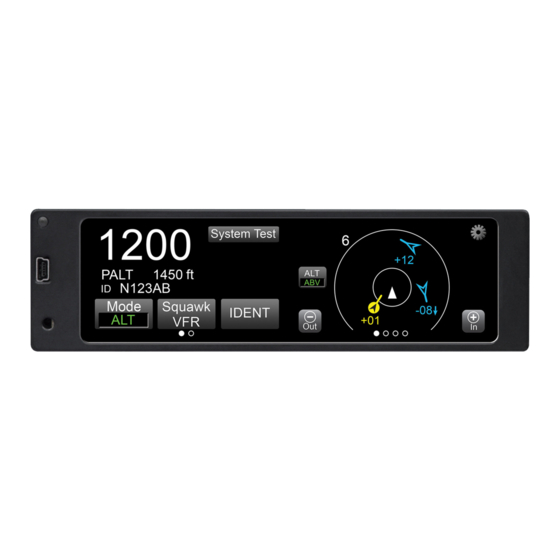
Lynx NGT-9000 Operation ® TRANSPONDER OPERATION The transponder receives interrogations from surrounding aircraft and from ATC and then transmits replies. The transponder application is the first screen on the left side of the display as indicated by the application indicator. See Figure 2-5 and the functional description below for operating instructions. -
Page 36: Current Pressure Altitude
Operation Lynx NGT-9000 ® Current Pressure Altitude The current pressure altitude (PALT) is located below the Squawk Code. A value greater than 99,000 ft will set the value to 99900 with amber text. An invalid pressure altitude is shown as amber dashes. Flight ID / Call Sign The Flight ID or Call Sign (tail number) is located below the PALT. -
Page 37: Squawk Vfr Button
Lynx NGT-9000 Operation ® Squawk VFR Button Tap the Squawk VFR toggle button to change the transponder squawk code to a predefined (1200) VFR value. The value shown on the button is the code that is activated when the button is tapped. A second press reverts the transponder to the previous squawk code. -
Page 38: Figure 2-7: Example Of System Test Screen
Operation Lynx NGT-9000 ® Self Test In Progress System Status ADS-B In: Pass ADS-B Out: Pass FIS-B: Pass GPS: Pass TAS: Fail Transponder: Pass Figure 2-7: Example of System Test Screen • If a “Fail” or External Fail” is shown for any of the system functions, then the message “Self-Test Failure”... -
Page 39: Traffic Operation
Lynx NGT-9000 Operation ® TRAFFIC OPERATION The Lynx MultiLink Surveillance System monitors the airspace around the aircraft using ADS-B In (and TAS if equipped) to communicate with like equipped aircraft with ADS-B Out and shows these other aircraft on the screen. When within range of a participating ground station TIS-B and ADS-R traffic services are also shown on the screen. -
Page 40: Traffic Symbols
Operation Lynx NGT-9000 ® Transponder Mode Options Selected Range Transponder Selected Selected Button Indication Traffic Info Button Traffic GS Traffic ID Banner 1200 XPDR N333TL 150 kts N333TL 150 kts STBY STBY Traffic Mode Indicator Zoom In Altitude Directional Ownship Zoom Out Mode Circle indicates symbol is selected... -
Page 41: Traffic Display Priority
Lynx NGT-9000 Operation ® • A velocity vector arrow may be appended to the right side of a traffic symbol to indicate that the intruder aircraft is ascending (up arrow) or descending (down arrow) faster than 500 fpm. No arrow is shown for intruder aircraft in level flight, or for those moving vertically slower than ±500 fpm, or for non-altitude-reporting intruder aircraft. -
Page 42: Table 2-4: Traffic Symbols
Operation Lynx NGT-9000 ® Table 2-4: Traffic Symbols SyMbol deScriPtion - exaMPle Airborne Directional Traffic Advisory (TA) (Panel mount with TAS option only) Airborne Directional Proximity Advisory (PA) * (Panel mount with TAS option only) Airborne Directional Other Traffic (OT) * (Panel mount only) Airborne Non-directional (TA) Airborne Non-directional (PA) *... -
Page 43: Range Rings
Lynx NGT-9000 Operation ® Range Rings The range rings are oriented around the ownship. A range indicator is shown outside the upper left corner of the outer most ring. Bearing indicators are shown on the 2 nm range ring. The range ring setting is controlled by the zoom buttons. -
Page 44: Tfc Button
Operation Lynx NGT-9000 ® TFC Button The Traffic (TFC) button replaces the Altitude Mode button when the status of the aircraft is On-Ground. The button also activates TAS (optional) when the aircraft is On-Ground. A description of each mode is detailed below: •... -
Page 45: Traffic Mode Indicator
Lynx NGT-9000 Operation ® Traffic Mode Indicator The Traffic Mode Indicator is available only when a Lynx NGT-9000 with TAS is installed. Otherwise the “ADS Only” is assumed to be operating for non-TAS installs. The indicator is shown above the Zoom in (+) button. The possible modes of operation are detailed below: •... -
Page 46: Figure 2-10: Traffic Options Screen - Status
Operation Lynx NGT-9000 ® • “2D” - 2D Nav, no integrity [Sufficient satellites to compute a lateral position, but not to compute either HPLSBAS or HPLFD] • “3D” - 3D Nav, no integrity [Sufficient satellites to compute a lateral and vertical position, but not to compute either HPLSBAS or HPLFD] •... -
Page 47: Options - Settings
Lynx NGT-9000 Operation ® Options - Settings The Settings screen provides the following information and functionality: See Figure 2-11. • Radio buttons to set the traffic altitude mode (Normal, Above, and Unrestricted). This selects the default altitude mode used when the aircraft goes in-air. -
Page 48: Tis-B No Coverage Indicator
Operation Lynx NGT-9000 ® TIS-B No Coverage Indicator When configured to be enabled, the indicator is located next to the Zoom Out button and is shown when TIS-B / ADS-R data is not available in the area (i.e. out of range of a ADS-B ground station). •... -
Page 49: Selected Traffic Id
Lynx NGT-9000 Operation ® Selected Traffic ID The Selected Traffic ID appears along the right side of both screens after a traffic symbol is pressed. The Traffic ID is removed when the selected traffic symbol is tapped, a Traffic Advisory (TA) occurs, or if the selected traffic is no longer being tracked. -
Page 50: Weather Operation
Operation Lynx NGT-9000 ® wEATHER OPERATION Flight Information Service Broadcast (FIS-B) service is available only from a ground station that is in range to aircraft equipped with UAT receivers. The FIS-B broadcast provides a graphical and textual display of weather and aeronautical information. Alternate weather displays and PED’s may show the weather data differently than what is shown in this pilot’s guide. -
Page 51: Map Elements
Lynx NGT-9000 Operation ® FIS-B Graphical Weather Application The Graphical Weather Application is located in the second screen position as indicated by the Application Indicator. The Graphic Application is a simplified moving map with depiction of ownship and the ability to selectively overlay graphical FIS-B products such as AIRMET, NEXRAD, TFR, METAR, and SIGMET. -
Page 52: Information Button (I)
Operation Lynx NGT-9000 ® • The land masses are black. Bodies of water are dark blue. Depiction of NEXRAD weather radar data is overlaid on the map. Map areas where NEXRAD data has not been received are indicated using a gray semi-transparent graphical overlay. This will cause land masses to appear grey and water to appear light blue. -
Page 53: Table 2-5: Airport Symbols
Lynx NGT-9000 Operation ® Table 2-5: Airport Symbols deScriPtion SyMbol Towered Soft Surfaced Airport Non-towered Soft Surfaced Airports Towered Hard Surfaced Small Airports (1,500 to 8,069 ft runway) Non-towered Hard Surfaced Small Airports (1,500 to 8,069 ft runway) Towered Hard Surfaced Large Airports (>... -
Page 54: Metar
Operation Lynx NGT-9000 ® METAR METAR is a report of weather conditions at airports represented graphically and consists of the FAA Flight Rules and Weather Conditions. The flight rules icons shows the FAA flight rules for each airport based on the visibility and cloud cover conditions. The weather conditions icons indicates the weather conditions at each airport based on precipitation, winds, and visual obstructions. -
Page 55: Traffic Button
Lynx NGT-9000 Operation ® Traffic Button This button is located on the far left side of the screen and is labeled “TFC” with a left facing triangle. Tap the button to return to the Traffic Application screen. Zoom Buttons Zoom In (+) and Zoom Out (-) buttons are located on the bottom of screen. -
Page 56: Map Options Button
Operation Lynx NGT-9000 ® Map Options Button The gear shaped Options Button is located in the upper right corner of the map screen. Tapping the button opens the Options screen that has three latch buttons located on the bottom of the screen. These buttons are labeled ON/OFF, Declutter, and Done. -
Page 57: Figure 2-17: Weather Map Legend Screen
Lynx NGT-9000 Operation ® Figure 2-17: Weather Map Legend Screen Pilot’s Guide 2-31... -
Page 58: Display Area
Operation Lynx NGT-9000 ® Display Area The left display area is used to show the meaning of map elements provided by FIS-B products. It is identified with the label “Legend”. A scroll bar on the right side provides an indication that additional information can be seen by using an up/down drag action. -
Page 59: Weather Map Text Screen
Lynx NGT-9000 Operation ® Weather Map Text Screen The Weather Map Text is shown on the left screen after the Information button is tapped. The screen is removed from view when another application is activated on the right screen or if the selected map element is deselected. -
Page 60: Product Select List Window
Operation Lynx NGT-9000 ® Product Select List Window The window shows a list of product types to select. Tapping the item will select the product type. Only one product type can be selected at a time. The available product are METAR, TAF, and NOTAM. Use a slide action to scroll the window up and down. -
Page 61: Traffic Button
Lynx NGT-9000 Operation ® The winds aloft display properties are defined in Figure 2-22. Figure 2-22: Winds Aloft Map Elements Traffic Button This button is located on the far left side of the screen and is labeled “TFC” with a left facing triangle. Tap the button to return to the Traffic Application screen. -
Page 62: Aloft Button
Operation Lynx NGT-9000 ® Aloft Button This button is located on the left side of the screen and is labeled “Aloft” with white text and the active selection labeled either “Wind” or “Temperature” with green text. Tap the button to select the other screen function. -
Page 63: Fis-B Textual Application
Lynx NGT-9000 Operation ® FIS-B Textual Application The Textual Application is available on the right screen and is located in the fourth screen position as indicated by the Application Indicator. This application screen displays textual weather information products for selected airports provided by FIS-B. The products available are METAR (Meteorological Aviation Report), NOTAM (Notice to Airmen) , and TAF (Terminal Area Forecast). -
Page 64: Airport Button
Operation Lynx NGT-9000 ® Airport Button This button is located to the right of the Traffic button is labeled with the Selected Airport identifier. This information is also shown below in the display area. Tap the button to open the Edit Airport ID window. Edit Airport ID Window This window is used to enter an Airport ID that is shown on the airport button and the display. -
Page 65: Favorites Button
Lynx NGT-9000 Operation ® Favorites Button This button is labeled with a amber star icon. Tap the button to open the Favorites Pick List window. Favorites Pick List Window This window is used to select a pre-saved Airport ID. See Figure 2- •... -
Page 66: Product Button
Operation Lynx NGT-9000 ® Product Button This button is labeled with the current selected product. Tap the button to open the Product Pick List window. Product Pick List Window This window is used to select an available FIS-B Textual Product, which are METAR, NOTAM , and TAF. - Page 67 Lynx NGT-9000 Operation ® In the Calibration screen touch and release each target shown. (Four calibration targets and two verification targets). Each must be completed within 15 seconds or the Calibration Time out message is shown. The unit returns to the main screen. If normal operation is desired cycle power to the unit or tap the Reboot text on the main screen followed by tapping the Main App >...
- Page 68 Operation Lynx NGT-9000 ® Page intentionally blank 2-42 Pilot’s Guide...
-
Page 69: Chapter 3: Controls And Indicators
Lynx NGT-9000 Controls and Indicators ® CHAPTER 3 CONTROLS AND INDICATORS INTRODUCTION This chapter describes the controls, indicators, and other devices that could be interfaced to the panel and remote mounted Lynx NGT- 9000. COCkPIT SwITCHES Cockpit switches are optional and may not be a part of the aircraft installation. -
Page 70: Alternate Display
Controls and Indicators Lynx NGT-9000 ® When the GPS has “failed”, the lamp is “ON”. GPS failures happen when: The Lynx NGT-9000 internal GPS indicates a failure. Aircraft is On-Ground and the GPS has acquired position, but the signal is lost for more than 2 minutes. Aircraft is In-Air and the GPS has not acquired position within 2 minutes (either startup or had position and lost it). -
Page 71: Proximity Advisory Symbol
Lynx NGT-9000 Controls and Indicators ® Proximity Advisory Symbol The Proximity Advisory (PA) represents an intruder aircraft that has not generated a TA, but which is within a horizontal range of 4 nmi and a relative altitude of ±1200 ft. The symbol is white or cyan on color alternate displays. -
Page 72: Aural Announcements
Controls and Indicators Lynx NGT-9000 ® AURAL ANNOUNCEMENTS “Traffic, Traffic” This normal aural component of a traffic advisory is announced once over the cockpit speakers or headset when a TA is first detected. This aural announcement will not be heard if audio is inhibited. -
Page 73: Cp-2500 Control Panel
Lynx NGT-9000 Controls and Indicators ® CP-2500 CONTROL PANEL The CP-2500 is the authorized Control Panel for the remote mount version of the Lynx NGT-9000R. The operational information provided in this section is limited. Refer to the CP-2500 Pilot’s Guide (0040- 17250-01) for specific details. - Page 74 Controls and Indicators Lynx NGT-9000 ® 4. In normal operation the user can change the operational mode, set the squawk code, view the current pressure altitude, and optionally set a flight ID mode. (The flight ID function is optional and is part of the configuration options set during installation of the Lynx NGT-9000R.) Select these items by rotating the large knob.
- Page 75 Lynx NGT-9000 Controls and Indicators ® 5. The CP-2500 has three buttons identified as I (Ident), V (VFR), and M (Menu). • Pressing the I (IDT) button activates the IDENT message to be sent by the ADS-B unit for 18 sec. IDENT is displayed while this message is being sent.
- Page 76 Controls and Indicators Lynx NGT-9000 ® 6. Messages being received from the Lynx NGT-9000R have priority over normal display operation and are seen scrolling across the display. Entering the menu mode will stop the messaging until the menu mode is exited. Rotating the large knob scrolls through the prioritized messages and the normal display operation (showing operational mode and squawk code).
-
Page 77: Chapter 4 Principles Of Tas Operation
Lynx NGT-9000 Principles of TAS Operation ® CHAPTER 4 PRINCIPLES OF TAS OPERATION INTRODUCTION This chapter describes Traffic Advisory (TA) criteria and other factors that affect the display of traffic symbols for models of the Lynx NGT-9000 with a Active Traffic Awareness System (TAS). Table 4-1 summarizes the criteria necessary to display a traffic advisory. -
Page 78: Sensitivity Level B
Principles of TAS Operation Lynx NGT-9000 ® Sensitivity Level B Sensitivity level B consists of two criteria for displaying a TA: The intruder aircraft enters into an area of airspace surrounding ownship defined by a 0.55 nmi horizontal radius and a height of ±800 ft from ownship. -
Page 79: Table 4-1: Traffic Advisory Situations
Lynx NGT-9000 Principles of TAS Operation ® Table 4-1: Traffic Advisory Situations other aircraFt iS ShiP ShiP detected SPeed Within a 0.2 nmi horizon- tal radius and a +/- 600 ft Below relative altitude. 2000 ft Within 15-20 sec of CPA * Within a 0.55 nmi horizon- tal radius and a +/- 800 ft Above... -
Page 80: Ta Symbol Duration
Principles of TAS Operation Lynx NGT-9000 ® TA SyMBOL DURATION A TA symbol remains on the screen for at least 8 seconds, even if the intruder aircraft no longer meets the TA criteria, as long as the Lynx NGT-9000 continues to track the aircraft. OTHER AIRCRAFT GROUND FILTERING If your aircraft is at or below 1700 ft AGL, the traffic awareness system (TAS) will not display or calculate alerts for other aircraft which are... -
Page 81: Figure 4-1: Traffic Display Mode And Tas Traffic Zone Graphic
Lynx NGT-9000 Principles of TAS Operation ® Not To Scale Up to 35 nmi +9900ft +9000 ft Up to 35 nmi Up to 35 nmi +2700 ft 4 nmi +1200 ft 0.55 nmi +800 ft 0.2 nmi +600 ft TAS Sensitivity Level A * This area or 20 seconds to CPA 0 ft –... - Page 82 Troubleshooting Lynx NGT-9000 ® Page intentionally blank Pilot’s Guide...
-
Page 83: Chapter 5: Troubleshooting
Lynx NGT-9000 Troubleshooting ® CHAPTER 5 TROUBLESHOOTING INTRODUCTION This chapter describes potential conditions that could occur while using the Lynx NGT-9000 MultiLink Surveillance System. Installations using a display for traffic or weather should also refer to that products Pilot’s Guide for troubleshooting information. It is recommended to crosscheck other cockpit displays/instruments for errors and/or data inconsistency. - Page 84 Principles of TAS Operation Lynx NGT-9000 ® Table 5-1: General Display Conditions for the Panel Mount Lynx NGT-9000 indication deScriPtion Traffic Unavailable • ADS-B is operational but heading and track are invalid. (Amber text) • GPS is failed. • TAS is in Standby. •...
-
Page 85: System Status Messages
Lynx NGT-9000 Troubleshooting ® SySTEM STATUS MESSAGES This section applies to the panel mount Lynx NGT-9000. The system status messages are seen on the screen either during start up or when the System Test button is pressed. The typical meanings of the messages are detailed in the bullets below. -
Page 86: Invalidities
Troubleshooting Lynx NGT-9000 ® INvALIDITIES Refer to Table 5-2 (panel mount) or Table 5-3 (remote mount) for answers to invalidities and other conditions noted on the Lynx NGT- 9000 system. An invalidity may not stop operation of the unit, but may degrade performance. - Page 87 Lynx NGT-9000 Troubleshooting ® Table 5-2: Troubleshooting for the Panel Mount Lynx NGT-9000 SyMPtoM cauSe/corrective actionS Internal fan is always active. Loss of temperature sensor data. Try clearing the failure by tapping the Restart button. If the problem continues, replacement of the Lynx NGT- 9000 may be required.
- Page 88 Troubleshooting Lynx NGT-9000 ® Table 5-2: Troubleshooting for the Panel Mount Lynx NGT-9000 SyMPtoM cauSe/corrective actionS • Compatible displays may GPS-Acquiring (On Ground – no previous position fix). indicate “STANDBY” or The GPS may need up to 4 “DATA-FAIL” and WI- minutes to provide a position after FI information is not power is applied to the Lynx NGT-...
- Page 89 Lynx NGT-9000 Troubleshooting ® Table 5-2: Troubleshooting for the Panel Mount Lynx NGT-9000 SyMPtoM cauSe/corrective actionS • No targets are shown on The aircraft is not in an ADS-B (UAT / 1090ES) coverage area, or the tar- the traffic screen. gets are not transmitting ADS-B data, •...
- Page 90 Troubleshooting Lynx NGT-9000 ® Table 5-2: Troubleshooting for the Panel Mount Lynx NGT-9000 SyMPtoM cauSe/corrective actionS The traffic symbols on the Non-directional traffic symbols on traffic display are non-direc- the traffic display is due to one of the tional (diamond shape) following reasons: The directional information that is being received by the MSS...
-
Page 91: Table 5-3: Troubleshooting For The Remote Mount Lynx Ngt-9000
Lynx NGT-9000 Troubleshooting ® Table 5-3: Troubleshooting for the Remote Mount Lynx NGT-9000R SyMPtoM cauSe/corrective actionS • CP-2500 displays “ADS- The Lynx NGT-9000 is not B SYSTEM FAIL” and operating: “XPDR FAIL”. Verify NGT-9000 breaker is • If installed, ADS-B Out closed. - Page 92 Troubleshooting Lynx NGT-9000 ® Table 5-3: Troubleshooting for the Remote Mount Lynx NGT-9000R SyMPtoM cauSe/corrective actionS • CP-2500 displays no GPS-Acquiring (On Ground – no previous position fix). message for first 2 minutes, then displays The GPS may need up to 4 minutes to provide a position “GPS-INIT”...
- Page 93 Lynx NGT-9000 Troubleshooting ® Table 5-3: Troubleshooting for the Remote Mount Lynx NGT-9000R SyMPtoM cauSe/corrective actionS • CP-2500 displays “NO The FIS-B data is not being trans- mitted to the compatible weather ADS-B COVERAGE”. display. • No data on the No ground station is in range.
- Page 94 Troubleshooting Lynx NGT-9000 ® Table 5-3: Troubleshooting for the Remote Mount Lynx NGT-9000R SyMPtoM cauSe/corrective actionS • CP-2500 displays “NO The aircraft is not in an ADS-B ADS-B COVERAGE”. (1090ES or 978 UAT) coverage area, and the targets are not trans- •...
-
Page 95: Appendix A: Record Of Important Information
APPENDIx A RECORD OF IMPORTANT INFORMATION Dealer Information Name Address City, State, Zip Telephone Equipment Information Date of Purchase Installation Date Model Number Part Number Serial Number Mod Letter Software Release Aircraft Information Aircraft Make Aircraft Model Serial Number N Number Register this product online at: www.l-3avionics.com/warrantyregistration Pilot’s Guide... - Page 96 Aviation Products 0040-17000-01 Revision E (July 24, 2015)
Need help?
Do you have a question about the Lynx NGT-9000+ and is the answer not in the manual?
Questions and answers
How to sync the xpder w an iPhone or iPad?