Table of Contents
Advertisement
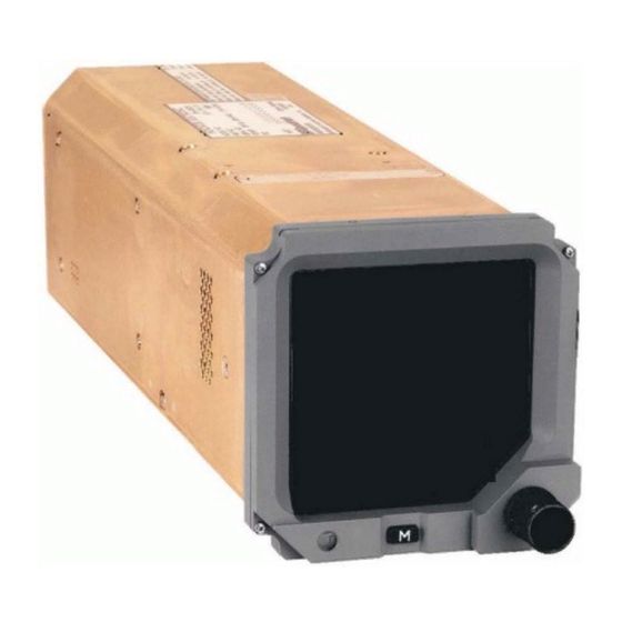
Electronic Standby Instrument System
Model: GH-3100
Part Number: 501-1860-(xxx1)
Part Number: 501-1860-(xxx3)
Installation and Operation Manual
This
manual
contains
information for the GH Electronic Standby Instrument
System. Information in this manual includes the following
products: GH-3100 Electronic Standby Indicator (with 1.3,
1.4 or 3.0 software), DCM-3100 Detachable Configuration
Module, and MAG-3000 / MAG-3100 Magnetometer. This
information is supplemented and kept current by
revisions, service letters and service bulletins.
nd
5353 52
Street, S.E.
Grand Rapids, MI 49512-9704, USA
L3aviationproducts.com
installation
and
operating
TP-559 (Revision K)
March 30, 2017
Advertisement
Table of Contents

Subscribe to Our Youtube Channel
Related Manuals for L3 Aviation Products GH-3100

Summary of Contents for L3 Aviation Products GH-3100
- Page 1 GH Electronic Standby Instrument System. Information in this manual includes the following products: GH-3100 Electronic Standby Indicator (with 1.3, 1.4 or 3.0 software), DCM-3100 Detachable Configuration Module, and MAG-3000 / MAG-3100 Magnetometer. This information is supplemented and kept current by revisions, service letters and service bulletins.
-
Page 2: Foreword
This manual assumes familiarity with the setup and operation of the aircraft systems that interface with the GH-3100. Standard installation practices prescribed in FAA Advisory Circular No. 43.13-2B must be followed. -
Page 3: About This Manual
TSO approvals. SECTION 2 - INSTALLATION This section contains instructions to locate, assemble and install the GH-3100 Electronic Standby System as well as information for unpacking equipment, and inspection procedure for in-shipment damage. -
Page 4: References
GH-3100 Installation & Operation Manual References To get an up-to-date listing of all L3 Aviation Products technical publications and service literature go to w ww.L3aviationproducts.com , click on the Customer Support tab, select Technical Publications, and 2 1 T 2 1 T 2 1 T 2 1 T select Current Publications on the left side of the screen. - Page 5 GH-3100 Installation & Operation Manual PUBLICATION DESCRIPTION SB501-1860-10 Service Bulletin - Release of 2.1 software in support of Gulfstream G450 program. SB501-1860-11 Service Bulletin - Release Software 1.1. New features include the capability to compensate IAS with DCM-3100 loaded constants K1 and K2.
-
Page 6: Revision Highlights
B-1 thru B-4 REVISION HIGHLIGHTS Revision K is a republication. This republication completely replaces the existing manual. New and revised material for the GH-3100 Installation Manual has been added. These changes include: • Update company name and email/web site. •... -
Page 7: Table Of Contents
List of Abbreviations ............................x SECTION 1 GENERAL INFORMATION Introduction ........................... 1-1 Functional description ........................1-3 1.2.1 Electronic Standby Indicator (GH-3100) ..................1-4 1.2.2 Detachable Configuration Module (DCM-3100) ................1-5 1.2.3 Magnetometer (MAG-3000) ......................1-5 1.2.4 Magnetometer (MAG-3100) ......................1-5 Specifications .......................... -
Page 8: Table Of Contents
Introduction ........................... 2-1 Unpacking and inspecting ......................2-1 2.2.1 Transport and Storage Considerations ..................2-1 Installation Procedures........................2-2 2.3.1 GH-3100 Electronic Standby Indicator ..................2-2 2.3.2 DCM-3100 Detachable Configuration Module ................2-3 2.3.3 Electrical Connections ........................2-6 2.3.4 Installation Guidelines for MAG-3000 Magnetometer ..............2-7 2.3.5... - Page 9 Air Data Display .......................... 5-27 5.3.5 NAV Displays ..........................5-28 5.3.6 Magnetic Heading Display Data ....................5-34 APPENDIX A GH-3100 INTERFACE SIGNAL NAME & CABLE CHARACTERISTICS Introduction ...........................A-1 Digital Interface ..........................A-1 A.2.1 ARINC 429 Input BUS ........................A-1 A.2.2 CSDB Input BUS ...........................A-2 A.2.3...
-
Page 10: List Of Illustrations
1-1: GH-3100 Electronic Standby Instrument System ................1-2 1-2: JT-147A Calibration Test Set ......................1-11 2-1: DCM-3100 Outline Dimensions ...................... 2-3 2-2: GH-3100 Outline Dimensions and J1 Pin Assignments ..............2-4 2-3: GH-3100 Cable Assembly (J1) ....................... 2-6 2-4: System Electrical Interface Diagram with MAG-3000 ..............2-9 2-5: System Electrical Interface Diagram with MAG-3100 .............. - Page 11 Page 1-1: GH-3100 System Components ....................... 1-1 1-2: GH-3100 Configuration ........................1-3 2-1: GH-3100 Installation Kit P/N 504-1895-07 ..................2-2 2-2: Magnetometer Installation Kit, P/N 504-1895-05 ................2-7 2-3: Magnetometer Installation Kit, P/N 504-1895-18 ................2-7 3-1: Installation Data Record ....................... 3-10 4-1: Indicated Airspeed ..........................
-
Page 12: List Of Abbreviations
GH-3100 Installation & Operation Manual List of Abbreviations Symbol or Symbol or Definition Definition Acronym Acronym 3ATI 3” Air Transport Instrument Inner Marker Aircraft Inch A/C EFF Aircraft Effectivity InHg Inches of Mercury ac or AC Alternating Current Kilogram Air Data Computer... -
Page 13: General Information
General Information 1.1 INTRODUCTION This section includes functional descriptions and equipment specifications for the GH-3100 Electronic Standby Instrument System. Included at the end of this section is a list of equipment required but not supplied with the system. A list of system components is provided in Table 1-1. Installation kits are called out in paragraph 1.6 and described in the installation section. - Page 14 GH-3100 Installation & Operation Manual GH-3100 DCM-3100 MAG-3000 MAG-3100 Figure 1-1: GH-3100 Electronic Standby Instrument System Page 1-2 General Information TP-559 March 30, 2017 Revision K...
-
Page 15: Functional Description
Installation & Operation Manual 1.2 FUNCTIONAL DESCRIPTION The GH-3100 Electronic Standby Instrument System provides a backup system for the following information: attitude, air data, heading, and navigation. Table 1-2 provides a list of currently available GH-3100 Electronic Standby Indicator's, for software versions 1.3, 1.4 and 3.0. -
Page 16: Electronic Standby Indicator (Gh-3100)
• Three axis solid state Magnetometer input for Magnetic Heading (RS-422) • ARINC 705 Heading Reference (ARINC 429) When equipment is connected to and configured for the above interfaces, the GH-3100 provides the following functions: INTERFACE DESCRIPTION INTERFACE STANDARD FUNCTION... -
Page 17: Detachable Configuration Module (Dcm-3100)
The Magnetometer uses a three-axis magnetic sensor to sense magnetic fields. The field data is transmitted via an RS-422 bus to the Standby Attitude Indicator (GH-3100). The field data is used with the pitch and roll attitude of the Standby Attitude Indicator to compute the magnetic heading of the aircraft. -
Page 18: Specifications
GH-3100 Installation & Operation Manual 1.3 SPECIFICATIONS 1.3.1 GH-3100 PART NUMBER 501-1860-() (GH-3100) CERTIFICATION: USA (FAA) and Europe (EASA) See paragraph 1.3.1.1 and 1.3.1.2 for information. RTCA COMPLIANCE: Environmental Category: DO-160D see environmental qualification Software Category: DO-178B, criticality Level B & C Other: DO-187, DO-189, DO-192, DO-195, DO-196, And DO-208. - Page 19 GH-3100 Installation & Operation Manual 1.3.1.1 TSO Authorizations TSO NO. TSO ADDITIONAL MARKING TSO TITLE TSO-C2d (Type B) Airspeed Instruments TSO-C4c Bank and Pitch Instruments TSO-C6d Directional Instruments, Magnetic TSO-C8d (Type B) Vertical Speed Instruments (Rate-of-Climb) TSO-C10b (-1000 to 55,000 Ft)
-
Page 20: Dcm-3100
The Module has unlimited service life. 1.4 MODIFICATIONS AND SOFTWARE REVISIONS Modification (MOD) for the LRU components of the GH-3100 Electronic Standby Instrument System is identified by an entry on the S/N & I.D. on individual units. Software revision is shown on the display during the startup phase of the Electronic Standby Indicator. -
Page 21: Equipment Required Not Supplied
NOTE Equivalent tools and equipment may be used. Air Data Test Set: Used to verify air data operation of the GH-3100 Electronic Standby Indicator and purchased from various manufacturers. Cables and Wiring: The installer will supply all system wires and cables. All wires are #22 AWG (minimum) unless otherwise noted on interconnect wiring diagram. - Page 22 Required for GH-1000 and magnetometer installation. (Manufacturer: SmartTool M-D Building Products, 92346 or equivalent). Installation Kit (s): Installation Kit P/N 504-1895-07 for the GH-3100. Includes the following: • Mounting Clamp, P/N 566-1814-04 • Mating Connector, P/N MS3476L18-32S • Strain Relief Connector, P/N M85049/52S18W Installation Kit P/N 504-1895-05 for the MAG-3000.
-
Page 23: Installation Approval And Limitations
GH-3100 Installation & Operation Manual Figure 1-2: JT-147A Calibration Test Set 1.7 INSTALLATION APPROVAL AND LIMITATIONS The conditions and tests required for TSO approvals of this article are minimum performance standards. It is the responsibility of those desiring to install this article either on or within a specific type or class of aircraft to determine that the aircraft installation conditions are within the TSO standards. - Page 24 GH-3100 Installation & Operation Manual This page intentionally left blank. Page 1-12 General Information TP-559 March 30, 2017 Revision K...
-
Page 25: Installation
Section 2 Installation 2.1 INTRODUCTION This section describes the installation of the GH-3100 Electronic Standby Instrument System, in a step by step procedure. The installation activities in this section will be performed in the following order: • Determine component locations. -
Page 26: Installation Procedures
Installation & Operation Manual 2.3 INSTALLATION PROCEDURES Use the following procedures to install the GH-3100 Electronic Standby Indicator and MAG-3000 or MAG-3100 Magnetometer. After installation refer to the applicable post installation procedure for calibration, power-up and ground testing. Mating connector and wiring instructions are located in paragraph 2.3.3. -
Page 27: Dcm-3100 Detachable Configuration Module
This completes the indicator installation. Refer to paragraph 2.3.3 for electrical connections. 2.3.2 DCM-3100 Detachable Configuration Module Connect the Detachable Configuration Module to the wiring harness of the GH-3100 via the attached chain. Refer to Figure 2-1 for outline dimensions. - Page 28 GH-3100 Installation & Operation Manual Figure 2-2: GH-3100 Outline Dimensions and J1 Pin Assignments (Sheet 1 of 2) Page 2-4 Installation TP-559 March 30, 2017 Revision K...
- Page 29 GH-3100 Installation & Operation Manual Figure 2-2: GH-3100 Outline Dimensions and J1 Pin Assignments (Sheet 2 of 2) TP-559 Installation Page 2-5 Revision K March 30, 2017...
-
Page 30: Electrical Connections
GH-3100 Installation & Operation Manual 2.3.3 Electrical Connections The installer must take the following into consideration before installing the GH-3100 Electronic Standby Instrument System: • All wiring must be in accordance with industry-accepted methods, techniques, and practices. Refer to FAA Advisory Circular AC43.13-1A for aircraft wiring requirements. -
Page 31: Installation Guidelines For Mag-3000 Magnetometer
GH-3100 Installation & Operation Manual 2.3.4 Installation Guidelines for MAG-3000 Magnetometer Use the following information along with the MAG-3000 Installation Manual, publication number TP-633 when installing a MAG-3000. The Installation Kits shown in Table 2-2 or Table 2-3 are optional. -
Page 32: Installation Guidelines For Mag-3100 Magnetometer
GH-3100 Installation & Operation Manual 2.3.5 Installation Guidelines for MAG-3100 Magnetometer Use the following information along with the MAG-3100 Installation Manual, publication number 0040-21200-01 when installing a MAG-3100. The Installation Kits shown in Table 2-2 or Table 2-3 are optional. - Page 33 GH-3100 Installation & Operation Manual Figure 2-4: System Electrical Interface Diagram with MAG-3000 TP-559 Installation Page 2-9 Revision K March 30, 2017...
- Page 34 GH-3100 Installation & Operation Manual Figure 2-5: System Electrical Interface Diagram with MAG-3100 (Sheet 1 of 2) Page 2-10 Installation TP-559 March 30, 2017 Revision K...
- Page 35 GH-3100 Installation & Operation Manual Figure 2-5: System Electrical Interface Diagram with MAG-3100 (Sheet 2 to 2) TP-559 Installation Page 2-11 Revision K March 30, 2017...
- Page 36 GH-3100 Installation & Operation Manual This page intentionally blank Page 2-12 Installation TP-559 March 30, 2017 Revision K...
-
Page 37: Installation Checkout
3.2 POST INSTALLATION CHECKS (INITIAL SYSTEM INSTALLATION) This procedure will validate the installation and return to service of the individual components included in the GH-3100 Electronic Standby Instrument System. Post installation checks are used for first time installations only. 3.2.1 Electronic Standby Indicator Check Aircraft or unit should not be placed into motion or be in motion during indicator alignment. -
Page 38: Magnetometer Check
Attitude compensation does not affect the GH-3100 computed pitch display. Attitude differences between the GH-3100 and MAG-3000 (or MAG-3100) are automatically compensated by the utilization of the MAT-3000A (or MAT-3100) Transmitter Assembly (refer to JT-147A) during steps (1) - (7). - Page 39 Fast Erect the GH-3100, wait approximately 3 seconds, and then momentarily depress the Data Entry button, wait while the attitude compensation data is being written to the DCM-3100. When prompted by the message on the Calibration Test Box display, remove power from the GH-3100 system.
- Page 40 Apply power to the GH-3100 instrument system and wait approximately 3 minutes for the "Aligning" message to disappear from the GH-3100 Indicator display. Align the aircraft to a cardinal heading. Fast erect the GH-3100 Indicator, wait approximately 3 seconds, and then read the heading displayed on the GH-3100 Indicator. The displayed heading must not deviate from the actual heading by more than what system requirements allow.
- Page 41 ILS information. Set up a valid ILS input to GH-3100 Indicator. Figure 3-2: ILS Display Select ILS normal display using the GH-3100 Indicator menu and observe normal indication of the following ILS display data (refer to Figure 3-2). •...
- Page 42 This Paragraph only applies to aircraft with the indicator configured to display VOR information. Set up a valid VOR input to GH-3100 Indicator. Figure 3-3: VOR Display Select VOR normal display using the GH-3100 Indicator menu and observe normal indication of the following VOR display data (refer to Figure 3-3). •...
- Page 43 GH-3100 Installation & Operation Manual Select DME normal display using the GH-3100 Indicator menu and observe normal indication of the following DME display data (refer to Figure 3-4). • Ground Speed in Knots (KTS) • Hold Annunciator (optional) • Slant Range Distance in Nautical Miles (NM) •...
- Page 44 TACAN information. Set up a valid TACAN input to GH-3100 Indicator. Figure 3-6: TACAN Display Select TACAN normal display using the GH-3100 Indicator menu and observe normal indication of the following TACAN display data (refer to Figure 3-6). •...
- Page 45 GH-3100 Installation & Operation Manual Use the air data test set to provide an adequate increasing (higher/positive) airspeed rate of change to observe airspeed tape operation. Observe and record the air speed tape information as shown in Table 3-1. NOTE If static source error correction is programmed, computed air data will differ from test set values by the amount of static source error correction.
- Page 46 GH-3100 Installation & Operation Manual Table 3-1: Installation Data Record Test Paragraph Test Data Test Date:__________________ Aircraft Serial Number:______________ Location:___________________ Start Time:________________________ Completion Time:__________________ Indicator / Air Data Test Set Comparison Indicator Display (observed) Air Data Test Set (setting) Altitude 10,000 feet ±...
-
Page 47: Post Installation Checks (Remove And Replace Checkout)
Installation & Operation Manual 3.2.3 Post Installation Checks (Remove and Replace Checkout) 3.2.3.1 Electronic Standby Indicator Check The following instructions are used only after a GH-3100 is removed for replacement or repair. CAUTION The DCM-3100 is electrostatic sensitive device when not connected to the GH-3100 Indicator. - Page 48 Apply power to the GH-3100 instrument system and wait approximately 3 minutes for the "Aligning" message to disappear from the GH-3100 indicator display. Align the aircraft to a cardinal heading. Fast erect the GH-3100 indicator, wait approximately 3 seconds, and then read the heading displayed on the GH-3100 Indicator. The displayed heading must not deviate from the actual heading by more than what system requirements allow.
-
Page 49: Maintenance
4.2 CONTINUED AIRWORTHINESS The GH-3100 and DCM-3100 do not require scheduled maintenance or scheduled overhaul. A need for maintenance is indicated when unit fails to operate using applicable inputs as described in this manual. - Page 50 NOTE Refer to Service Letter SL-186 to perform Altitude Accuracy Checks for GH-3100 systems using SSEC data. Set the barometric pressure on the display to 29.92 in Hg. Set pitot pressure on the air data test set to the normal cruise speed of the aircraft.
-
Page 51: Fault Isolation
4.3 FAULT ISOLATION Table 4-2 lists possible symptoms and corrective actions to assist the installer with fault isolation. In addition, refer the L3 Aviation Products Troubleshooting Guide (publication number: TP-603) for detailed troubleshooting instructions. For additional assistance call L3 Aviation Products, Customer Service (800-453-0288 or 616-949-6600). - Page 52 1. Check for valid ARINC 429 data from air data computer. display on GH indicator. • If valid contact L3 Aviation Products Customer service. • If no ARINC 429 data is present, check for correct input voltage to the air data computer.
-
Page 53: Return To Service
Installation & Operation Manual 4.4 RETURN TO SERVICE To validate the return to service of the GH-3100 Electronic Standby Instrument System, refer to the Post Installation checkout procedures for the GH-3100 and MAG-3000 (or MAG-3100). 4.5 DISPOSITION OF FAILED ITEMS 4.5.1 GH-3100 Electronic Standby Indicator... -
Page 54: Dcm-3100 Data Configuration Module
4.5.2 DCM-3100 Data Configuration Module The configuration module is not repairable and a new module must be purchased from the factory. Return defective components to: L3 Aviation Products Attn: Customer Service 5353 52nd Street, S.E. Grand Rapids, MI USA 49512-9704 Send a letter along with the defective part and include the following information: •... -
Page 55: Operation
Installation & Operation Manual Section 5 Operation 5.1 INTRODUCTION This section contains function descriptions and operation functions for the GH-3100 Electronic Standby Instrument System with software version 1.3, 1.4 or 3.0 installed. The Aircraft Flight Manual supplies specific configuration information. 5.2 FUNCTIONAL DESCRIPTION No scheduled maintenance is required to ensure continued airworthiness. -
Page 56: Menu Interface
GH-3100 Installation & Operation Manual 5.2.1.2 Push Button Key The push button key located on the lower middle portion of the indicator. The button is identified as a small rectangular button marked with a white capital “M” that illuminates for ease of locating. - Page 57 Menu items are shown. The possibility of the item being a selection depends on the configuration of the DCM-3100 module and/or the state of the GH-3100. 5.2.2.3.1 Fast Erect The FAST ERECT item is always in the menu item list.
- Page 58 GH-3100 Installation & Operation Manual MENU ITEM DISPLAY SUB MENU DISPLAY REQUIREMENT TO DISPLAY Always On Fast Erect Rotate the knob to adjust Always On Set Brightness Offset… the brightness. Press the knob when done. Fast Align Always On Rotate the knob to adjust the heading value.
- Page 59 GH-3100 Installation & Operation Manual 5.2.2.3.3 Fast Align The FAST ALIGN menu item is in the main menu. 5.2.2.3.4 Set Heading The SET HEADING menu item is used with Magnetic Heading Display Data. While in the SET HEADING function, if heading is no longer in the “free mode”, the SET HEADING function states that fact in the operational description.
- Page 60 GH-3100 Installation & Operation Manual 5.2.2.3.10 NAV Displays The NAV DISPLAYS... menu item is shown when displaying the VOR/ILS Mode with DME, TACAN Mode, or FMS Mode. When the NAV DISPLAYS... function is activated, the current menu list is replaced with the items from the following list which are relative to the active NAV Mode display: •...
-
Page 61: Operational Formats
GH-3100 Installation & Operation Manual 5.2.2.4.3 Display Option Retention The display option settings controlled by the following menu items are restored to the last selected values after power is cycled: • BRIGHTNESS OFFSET… • NAV [ON or OFF] • NAV MODE…... - Page 62 GH-3100 Installation & Operation Manual 5.2.3.3.1 Scale Lines As shown in Figure 5-2 the longest scale lines represent 10° increments of pitch on either side of the horizon line. Each of these 10° lines has a white number at both ends representing its distance in degrees from the horizon line.
- Page 63 GH-3100 Installation & Operation Manual 5.2.3.4 Aircraft Reference Symbol The aircraft reference symbol provides the reference point for the pitch ladder (refer to Figure 5-2). This symbol consists of two L-shaped “wings” and a fixed square boresight mark, each colored black with a white outline.
- Page 64 GH-3100 Installation & Operation Manual 5.2.3.8 Attitude Failure Indications For the Attitude Failure Indication, the pitch ladder, roll pointer, and slip/skid indicator are removed leaving the roll scale and the aircraft symbol visible on a cyan background. The large characters “ATT FAIL”...
- Page 65 GH-3100 Installation & Operation Manual 5.2.3.11 Processor Error Screens A warning, shown as a red X across the display or as a black screen with instructions are shown if errors are detected in the graphic or host processors as shown in Figure 5-5.
-
Page 66: Air Data Presentation
GH-3100 Installation & Operation Manual 5.2.4 Air Data Presentation Air data display appears as shown in Figure 5-6. Figure 5-6: Attitude Display with Airspeed and Altitude 5.2.4.1 Altitude Tape Altitude tape is presented on a vertical tape on the right side of the display area (refer to Figure 5-6) with the digital baro correction readout at the top of the tape. - Page 67 GH-3100 Installation & Operation Manual 5.2.4.1.2 Altitude Digital Readout Format The altitude digital readout box(s) and digital readout(s) is drawn “on top” of the altitude tape and attitude display area. Altitude tape movement will not interfere with the altitude digital readout display area.
- Page 68 GH-3100 Installation & Operation Manual When ALTITUDE DISPLAY ROLLING DIGITS is configured for ON, the right two digits of the altitude digital readout are paired in 20-foot increments, and the altitude digits “roll” inside a modified box. The rolling correspond to the altitude with an “odometer” style with all digits rolling downward for increasing altitude.
- Page 69 GH-3100 Installation & Operation Manual 5.2.4.1.4 Altitude Display Invalidity An invalid altitude display omits the tape tic marks, tape scale digits, the digital readout digits, the baro correction digits, and the optional chevrons When AIR DATA INVALIDITY TYPE is configured for BOX W/DESCRIPTOR and an invalid altitude display is shown, an “ALT”...
- Page 70 GH-3100 Installation & Operation Manual Vertical Speed Digital Readout (Maximum and Minimum Readout) When VERTICAL SPEED DIGITAL READOUT is configured ON and altitude data is valid and Vertical Speed data is greater than the limit 9,900 ft/min, then the Vertical Speed Digital Readout is shown at the limit in AIR DATA FAILURE COLOR based on unit configuration.
- Page 71 GH-3100 Installation & Operation Manual IAS Tape Direction can be configured in three ways. • When IAS INCREASE TAPE DIRECTION is configured for DOWN, the IAS tape moves down for increasing IAS as shown in Figure 5-9A, C, or D.
- Page 72 GH-3100 Installation & Operation Manual 5.2.4.1.8 Mach Digital Readout Format The mach digital readout is shown in the mach box positioned at the top of the IAS tape, at the left side of the display. The box is black with no border.
-
Page 73: Navigation Data
GH-3100 Installation & Operation Manual 5.2.5 Navigation Data Attitude and air data information is combined with navigation data when navigation operation is desired. Figure 5-11 shows a typical display in VOR Mode with DME. Figure 5-12 shows a typical display in ILS Mode with DME. - Page 74 GH-3100 Installation & Operation Manual Figure 5-12: ILS Mode with DME The test annunciator “NAV TST” is shown in the medium character size having NAV TST Annunciator Color based on unit configuration, replacing the source descriptor and its modifiers in the upper left side of the attitude display area.
- Page 75 GH-3100 Installation & Operation Manual Figure 5-14: TACAN Mode Three dashes “---” replace the digits in a navigation data field when the data for that field is invalid. The DME hold annunciator “H” is shown in the small character size, having DME "H" Annunciator Color based on unit configuration, preceding the DME distance digits.
- Page 76 GH-3100 Installation & Operation Manual 5.2.5.2.2 Left/Right Deviation Cross-Pointer Format The color of the left/right needle has the DEVIATION NEEDLES COLOR based on unit configuration with a black outline. The left/right needle’s width will not be greater than the width of the boresight mark, and its length is twice as long as 110% of its full-scale deflection.
-
Page 77: Heading Data
GH-3100 Installation & Operation Manual 5.2.5.8 Bearing Data The bearing data is shown in the lower right corner of the attitude display area above the area of the optional heading display, as shown in Figure 5-13. The bearing data is shown as three medium size digits with leading zeros. - Page 78 GH-3100 Installation & Operation Manual The heading tape tic marks are labeled at every 30 degrees of heading, starting at 0 degrees, with the two left-most digits of the corresponding three-digit heading (including leading zeroes). These heading tape numbers are white. At cardinal headings, the letters N, E, S, or W replace the respective heading scale numbers.
-
Page 79: Operational Functions
GH-3100 Installation & Operation Manual 5.3 OPERATIONAL FUNCTIONS 5.3.1 Power ON Sequence Starting with the application of +28.0 Vdc the indicator sequences through the following modes: • Power ON Self Test Mode • Identification Mode • Sensor Alignment Mode •... -
Page 80: Pitch And Roll Attitude Display
GH-3100 Installation & Operation Manual 5.3.1.2.3 Heading Calibration Check If heading is selected for display using a magnetometer as a reference and no calibration has been performed a message “Heading Calibration Required” is shown on the ID screen and heading will not be shown when in normal mode. -
Page 81: Slip / Skid Indicator
GH-3100 Installation & Operation Manual 5.3.2.1 Fast Erect Selecting Fast Erect through the main menu causes a rapid alignment of the vertical axis shown on the indicator to the current vertical axis of the aircraft. During FAST ERECT, aircraft must remain in straight and level, non-accelerated flight. -
Page 82: Nav Displays
GH-3100 Installation & Operation Manual 5.3.4.2.1 V Data When IAS PART 27/29 is configured for OFF, the V data is calculated from data supplied in the DCM- 3100. 5.3.4.2.2 V Power On Data When IAS PART 27/29 is configured for ON, the V Power On data is calculated from data supplied in the DCM-3100. - Page 83 GH-3100 Installation & Operation Manual Figure 5-19: Example of ARINC 429 NAV & CSDB NAV Interconnect 5.3.5.1 ILS Mode The indicator enters ILS Mode when the pilot chooses to display VOR / ILS information through the main menu and the NAV receiver is in the ILS mode. An ILS frequency is defined as having an odd number in the tenths of MHz position over the range of 108.10 MHz through 111.95 MHz.
- Page 84 GH-3100 Installation & Operation Manual 5.3.5.1.2 Left / Right Deviation Indicator When in ILS Mode the left / right deviation indicator presents Localizer information from the NAV receiver. 5.3.5.1.3 Up / Down Deviation Indicator When in ILS Mode the Up / Down deviation indicator presents glide slope information from the NAV receiver.
- Page 85 GH-3100 Installation & Operation Manual 5.3.5.4.2 Left/Right Deviation Indicator The left/right deviation indicator displays the difference between the Selected Course and the VOR Omnibearing, the TO annunciation reflects a deviation of less than or equal to 90 degrees, whereas FR annunciates deviations of greater than 90 degrees.
- Page 86 GH-3100 Installation & Operation Manual 5.3.5.6.1 FMS Descriptor Based on the FMS Descriptor configuration option, when in FMS Mode the source of the deviations is identified with the “FMS,” “FMS1,” “FMS2,” “FMS3,” “FMS4”, “GPS,” "GPS1", "GPS2", “NAVL,” or “NAVR” descriptor.
- Page 87 GH-3100 Installation & Operation Manual 5.3.5.8 TACAN Display Data If the unit is configured for TACAN TRANSCEIVER and the pilot uses the Menu to select the TACAN Mode in Normal operational state, the display data appear as the following: •...
-
Page 88: Magnetic Heading Display Data
If external heading information becomes invalid, the GH-3100 switches to operating in the “free mode”(using internal sensors only for heading calculations). The free mode is annunciated by display of the “DG”... -
Page 89: Appendix Agh-3100 Interface Signal Name & Cable Characteristics
This appendix defines digital interface label information and electrical characteristics of all input and output signal names to the GH-3100 Electronic Standby Instrument System. Sufficient data is included to use a bus reader for the purpose of identifying GH-3100 signal input and output characteristics and perform an electrical load analysis for the aircraft. -
Page 90: Csdb Input Bus
GH-3100 Installation & Operation Manual The following ARINC 429 labels are received at low speed (12.0 to 14.5 kbps) and are inputs from a TACAN receiver: • Label 002 - Time-To-Go (BCD) • Label 012 - Ground Speed (BCD) •... -
Page 91: Input Bus
Label 0A - Magnetometer data • Label 0C - Magnetometer fault data A.2.4 BUS Configuration Options Table A-1 provides a list of Bus Input Options available in the GH-3100. Table A-1: External Systems BUS Input Options BUS INPUTS HEADING VOR/ILS... -
Page 92: Electronic Standby Indicator, [J1 Connector
GH-3100 Installation & Operation Manual A.3 ELECTRONIC STANDBY INDICATOR, [J1 CONNECTOR] PIN A Signal Name: ARINC 429 OUTPUT_1B Signal Type: ARINC 429 Transmit Electrical Characteristics: High Speed ARINC 429 (100 kbps) Connection: Not Connected Comments: Reserved for factory testing. PIN B... - Page 93 GH-3100 Installation & Operation Manual Electronic Standby Indicator, [J1 connector] (Continued) PIN G Signal Name: ARINC 429 INPUT 2 A Signal Type: ARINC 429 Receive Configuration Option: Electrical Characteristics: Low Speed ARINC 429 (12.0 to 14.5 kbps) High Speed ARINC 429 (100 kbps) Connection: See Digital Interface information in paragraph A.2.
- Page 94 GH-3100 Installation & Operation Manual Electronic Standby Indicator, [J1 connector] (Continued) PIN M Signal Name: ARINC 429 INPUT 4 A Signal Type: ARINC 429 Receive Configuration Option: Electrical Characteristics: Low Speed ARINC 429 (12.0 to 14.5 kbps) High Speed ARINC 429 (100 kbps) Connection: See Digital Interface information in paragraph A.2.
- Page 95 GH-3100 Installation & Operation Manual Electronic Standby Indicator, [J1 connector] (Continued) PIN T Signal Name: ARINC 429 INPUT 6 B Signal Type: ARINC 429 Receive Configuration Option: Electrical Characteristics: Low Speed ARINC 429 (12.0 to 14.5 kbps) High Speed ARINC 429 (100 kbps) Connection: See Digital Interface information in paragraph A.2.
- Page 96 GH-3100 Installation & Operation Manual Electronic Standby Indicator, [J1 connector] (Continued) PIN Z Signal Name: CSDB INPUT 2A Signal Type: CSDB Receive Electrical Characteristics: Low Speed (12.5 kbps) Connection: See Digital Interface information in paragraph A.2. Comments: PIN a Signal Name:...
- Page 97 GH-3100 Installation & Operation Manual Electronic Standby Indicator, [J1 connector] (Continued) PIN f Signal Name: SPARE Signal Type: Electrical Characteristics: Connection: No Connection Comments: PIN g Signal Name: CHASSIS GND SIGNAL TYPE: Chassis Ground Electrical Characteristics: -------- Connection: Airframe Ground...
- Page 98 GH-3100 Installation & Operation Manual This page intentionally left blank. Page A-10 Appendix A TP-559 March 30, 2017 Revision K...
-
Page 99: Appendix Benvironmental Qualification Form
Installation & Operation Manual Appendix B Environmental Qualification Form This appendix includes the environmental qualifications forms required for the GH-3100 Electronic Standby Instrument system. Forms included are for the GH-3100 and DCM-3100. B.1 GH-3100 & DCM-3100 ENVIRONMENTAL QUALIFICATION FORM (Reference Document: 538-4004, Rev. F) - Page 100 GH-3100 Installation & Operation Manual Conditions Section Description of Tests Conducted Temperature and Altitude Equipment tested to Category A2. Except as follows: Low Temperature 4.5.1 Low operating temperature -40°C. High Temperature 4.5.2 & 4.5.3 In-Flight Loss of Cooling 4.5.4 Not applicable, Not Tested, External Cooling Not...
- Page 101 GH-3100 Installation & Operation Manual Conditions Section Description of Tests Conducted Radio Frequency 20.0 Equipment tested to Category YYP. Susceptibility Emission of Radio 21.0 Equipment tested to Category M. Frequency Energy Lightning Induced Transient 22.0 Equipment tested to Category B3F3. For Multi Burst and Susceptibility Stroke Reference SAE ARP5412 level 3.
- Page 102 Number GH-3100, Part Number: 501-1860-0403 and Detachable Configuration Module. Model: DCM- 3100, Part Number: 501-1870-( ). These test results apply to the following GH-3100 Part Numbers: 501-1860-0103, 501-1860-0203, 501- 1860-0303, 501-1860-0403, 501-1860-0503, 501-1860-0603, 501-1860-0703, 501-1860-0803, 501-1860- 1103, 501-1860-1203, 501-1860-1303, 501-1860-1403, 501-1860-1503, 501-1860-1603, 501-1860-1703, 501-1860-1803, 501-1860-2103, 501-1860-2203.
Need help?
Do you have a question about the GH-3100 and is the answer not in the manual?
Questions and answers