Advertisement
Quick Links
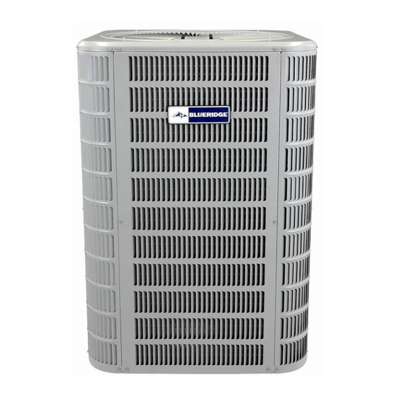
BHP15 SPLIT SYSTEM HEAT PUMP
This is a safety alert symbol and should never be ignored. When you see this symbol on labels or in
manuals, be alert to the potential for personal injury or death.
Table of Contents
Safety Precautions ......................................................2
Installation ...................................................................2
Electrical Connections .................................................5
Start-Up Procedure......................................................6
Operation .....................................................................7
Homeowner's Information .........................................10
NOTE TO INSTALLING DEALER
These instructions and warranty are to be given to the
owner or displayed near the indoor air handler unit.
Improper installation, adjustment, alteration, service
or maintenance will void the warranty. The qualified
installer or agency must use factory-authorized kits
or accessories when added to this products. Refer to
the individual instructions included with the specific
accessory kit.
Manufactured By
Blue Summit LLC
8201 C National Turnpike
Louisville, KY 40214
506318-03B
INSTALLATION INSTRUCTIONS
(R410A REFRIGERANT)
This manual must be left with the homeowner for future reference.
CAUTION
Save these instructions for future reference
These instructions are intended as a general guide and
do not supersede national, state or local codes in any
way.
Installation or repairs made by unqualified persons can
result in hazards to you and others. Installation MUST
conform with local building codes and with the National
Electrical Code NFPA 70/ANSI C1-1993 or current
edition and Canadian Electrical Code Part 1 CSA C22.1.
Before installing, modifying, or servicing system, main
electrical disconnect switch must be in the OFF position.
There may be more than 1 disconnect switch. Lock out
and tag switch with a suitable warning label. Electrical
shock can cause personal injury or death.
*P506318-03B*
Issue 1850
NOTE
WARNING
WARNING
(P) 506318-03B
Page 1 of 11
Advertisement

Summary of Contents for Blueridge BHP15
-
Page 1: Table Of Contents
INSTALLATION INSTRUCTIONS BHP15 SPLIT SYSTEM HEAT PUMP (R410A REFRIGERANT) This manual must be left with the homeowner for future reference. This is a safety alert symbol and should never be ignored. When you see this symbol on labels or in manuals, be alert to the potential for personal injury or death. -
Page 2: Safety Precautions
NOTE: Maximum liquid-line size is 3/8 in. O.D. for all These units are designed for use in residential and light commercial type buildings. Heat Pumps may only residential applications including long lines. be installed with indoor combinations listed in the Air Conditioning, Heating and Refrigeration Institute (AHRI) Outdoor Section Directory of Certified Products. - Page 3 Liquid Vapor Capacity Connections Tube Connections Tube Dia. Dia. Dia. Dia. -018 3/8” 3/8” 3/4” 3/4” -024 3/8” 3/8” 3/4” 3/4” -030 3/8” 3/8” 3/4” 3/4” -036 3/8” 3/8” 7/8” 7/8” -042 3/8” 3/8” 7/8” 7/8” -048 3/8” 3/8” 7/8” 7/8”...
- Page 4 Before making braze connections, be sure all joints are 1. Connect the vacuum pump to the center hose of the clean. Before heat is applied for brazing, dry nitrogen manifold gauge set, the low-pressure manifold gauge should be flowing through the tubing to prevent oxidation to the vapor service valve and the high pressure and scale formation on the inside of the tubing.
-
Page 5: Electrical Connections
Control Wiring Electrical Connections The control voltage is 24 VAC. NEC Class I insulated 18 AWG is required for control wiring. For lengths longer than 150 feet, contact your local distributor for technical service. WARNING Ensure the room thermostat is properly installed per instructions shipped with room thermostat. -
Page 6: Start-Up Procedure
Before final adjustment is made to the refrigerant charge, Start-Up Procedure it is imperative that proper indoor airflow be established. Airflow will be higher across a dry coil versus a wet coil. Check to ensure: Blower charts are calculated with a dry or wet coil basis. Recommended airflow is 350-450 CFM per ton (12,000 •... -
Page 7: Operation
Operation The outdoor unit and indoor blower cycle on demand from the room thermostat. When the thermostat blower switch is in the ON position, the indoor blower operates continuously. Emergency Heat Function (Room Thermostat) An emergency heat function is designed into some room thermostats. - Page 8 Low Pressure Switch (LO-PS) — When the low pressure During a single demand cycle, the defrost control will lock out the unit after the fifth time that the circuit is interrupted switch trips, the defrost board will cycle off the compressor, by any pressure switch wired to the control board.
- Page 9 Figure 4. H/P 15 SEER Wiring Diagram 506318-03B Issue 1850 Page 9 of 11...
-
Page 10: Homeowner's Information
Homeowner’s Information different manufacturers. The information below is typical for most thermostats. Ask your dealer for specific information WARNING regarding the model of thermostat installed. ELECTRICAL SHOCK HAZARD! Temperature Setting Levers Turn OFF electric power to unit before performing any maintenance or removing panels or doors. - Page 11 Important System Information of the air. Clogged condenser coils will lower the efficiency of your unit and could cause damage to the condenser. • Your system should never be operated without a clean air filter properly installed. Periodically, debris should be brushed from the condenser •...


Need help?
Do you have a question about the BHP15 and is the answer not in the manual?
Questions and answers