
Related Manuals for APG PG-7


Summary of Contents for APG PG-7
- Page 1 AUTOMATION P R O D U C T S GROUP, INC. Operator’s Manual PG-7 Full Access DOC. 9003312 Rev A2, 07/16 Automation Products Group, Inc. 0.561.8187 information@itm. www. .com...
-
Page 2: Table Of Contents
Rev. A2, 07/16 Table of Contents Warranty ......................3 Programming the PG7 .................4-23 Full Access Menu .................... 5 Accessing the Mode Setting................6 Mode Definitions .................... 6 Accessing/Exiting the Setup Menu ..............7 Maximum/Minimum Reset ................8 Units of Measure .................... 9 Using Custom Units ................ -
Page 3: Programming The
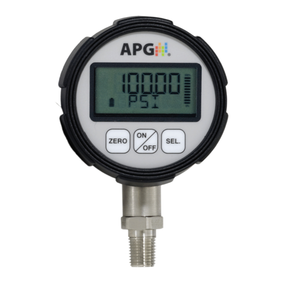
Rev. A2, 07/16 Programming the PG7 Battery Meter Bar Graph Zero (Z) Button Select (S) Button On/Off Button Each of the three buttons on the PG7 performs multiple functions. The primary function applies when in standard operating mode. The secondary functions are used for programming operations and when special features, such as Peak-Hold, are enabled. -
Page 4: Full Access Menu
Rev. A2, 07/16 CUSTOM ONLY MAXMIN FULL ACCESS MENU <= 120 psi CUSTOM MBAR INHG UNITS INH20 MMHG SELECT MULTIPLIER NEWTON > 120 psi CUSTOM P HOLD KGCM^2 FTH20 CMHG CUSTOM ONLY AUTO OFF, 2 MIN, 4 MIN, 8 MIN, 16 MIN, 32 MIN ADVSET HI RES, MEd Res, LO RES DEC PL... -
Page 5: Accessing The Mode Setting
Rev. A2, 07/16 Accessing the Mode Setting: Step 1: Simultaneously press and hold the On/Off button and the (S) button for approximately 3 seconds. This will bring up the 3 digit mode number. Step 2: Enter the desired mode number (see mode definitions below) by using (Z) to change the value of the flashing digit, and (S) to advance to the next digit. -
Page 6: Accessing/Exiting The Setup Menu
Rev. A2, 07/16 Accessing/Exiting the Setup Menu: Zero (Z) Button Select (S) Button On/Off Button Accessing the Setup Menu: Step 1: Simultaneously press and hold the On/Off button and the (S) button for approximately 3 seconds. This will bring up the 3 digit mode number. -
Page 7: Maximum/Minimum Reset
Rev. A2, 07/16 Maximum/Minimum Reset (MAXMIN): Pressing the (S) button while in standard operating mode will cycle between displaying the current pressure reading, the Maximum pressure reading and the Minimum pressure reading. The maximum and minimum readings will be stored until the gauge is powered down or the max/min readings are reset. -
Page 8: Units Of Measure
Rev. A2, 07/16 Units of Measure (UNITS): Allows the user to select the unit of measure to be displayed as the pressure reading. Options: For gauges over 120 psi: (pounds per square inch) (bar) (kilopascals) *CUSTOM (see “Using Custom Units” on next page) KGCM^2 (kilograms per cubic centimeter) (megapascals) -
Page 9: Using Custom Units
Rev. A2, 07/16 Using Custom Units (CUSTOM): The Custom Units setting allows the user to display a volumetric weight by applying a conversion factor to the pressure reading. NOTE: The conversion factor must be calculated using Pound per Square Inch (psi) as the base unit of measure. Setting the Custom Units feature: Step 1: Calculate the conversion factor from psi to the desired unit of measure. -
Page 10: Peak-Hold Feature
Rev. A2, 07/16 Peak-Hold (P HOLd): When the Peak-Hold is enabled, the gauge will display the “peak” or maximum pressure reading since the gauge was powered on or the Max/Min value was reset. NOTE 1: When the Peak-Hold feature is enabled, a small box containing the words PEAK HOLD will be displayed in the upper left corner of the display. -
Page 11: Advanced Settings
Rev. A2, 07/16 Advanced Settings (AdVSET): The Advanced Settings menu is used to customize the LCD display and to setup any optional features, such as an analog output. Auto-Off (AUTO): This function is applicable to battery powered units only. The Auto-Off feature allows the user to designate the time of inactivity (no buttons pushed) until the gauge automatically powers down. -
Page 12: Decimal Place
Rev. A2, 07/16 Decimal Place (dEC PL): The reading can be set to display in High Resolution (HI RES), Medium Resolution (MEdRES) or Low Resolution (LO RES) mode. Switching between resolutions will shift the displayed reading by one decimal place position. NOTE: Gauges without a decimal place position will display a dummy zero (or zeros) when the resolution is changed to medium or low. -
Page 13: Sample Rate
Rev. A2, 07/16 Sample Rate (SAMPLE): Adjusts the rate at which the gauge takes sample readings. NOTE: Setting the Sample Rate to “SLOW” will help preserve battery life (when applicable) and will also help to smooth rapidly fluctuating readings. Options: SLOW (4x/second), MEdIUM (8x/second), FAST (16x/second) Setting the Sample Rate feature: Step 1: Press the On/Off button to enter the main setup menu. -
Page 14: Bar Graph
Rev. A2, 07/16 Bar Graph 0% (bAR 0) & Bar Graph 100% (bAR100) Settings: Allows the user to define the reading values associated with 0% and 100% on the display bar graph. Bars will appear/disappear in 10% increments of the total span between the two values. NOTE: The 0% reference does not have to be the lower pressure setting;... -
Page 15: Range Adjustment
Rev. A2, 07/16 Full-Scale Range Adjust (RANGE): Allows the user to adjust the reading at full-scale pressure. The reading can be adjusted by +/-10% full-scale. NOTE: The pressure reading must be within 5% of the full-scale value in order to make Range adjustments. For example, a 1000 psi gauge would need to be reading between 950 psi and 1050 psi in order to adjust the Range feature. -
Page 16: Quick Calibration
Rev. A2, 07/16 Quick Calibration (CALIBR): Allows the user to perform a quick calibration of the zero and span. NOTE: Both zero pressure and full-scale pressure must be applied to the gauge in order to complete the quick calibration process. Performing Quick Calibration: Step 1: Press the On/Off button to enter the main setup menu. -
Page 17: Tare Feature
Rev. A2, 07/16 Tare (TARE): Enabling the Tare function will set the current pressure reading as the zero reference pressure in order to measure a net change in pressure as opposed to measuring the gross pressure. Enabling the Tare feature: Step 1: Press the On/Off button once to enter the main setup menu. -
Page 18: Default
Rev. A2, 07/16 Default (dEFAUL): Used to reset the gauge to the factory default settings. Resetting the gauge to factory default settings: Step 1: Press the On/Off button once to enter the main setup menu. Step 2: Press (Z) to cycle through the options until dEFAUL is displayed. Step 3: Press (S) to access the Default options. -
Page 19: Output
Rev. A2, 07/16 OUTPUT: Used to configure any optional gauges outputs, such as an analog signal or trip point relays. Analog Low (AL SET) & Analog High (AH SET) Setpoints: Allows the user to define the reading values associated with the Low Analog signal (i.e. - Page 20 Rev. A2, 07/16 Analog Low (AL CAL) & Analog High (AH CAL) Calibration: Allows the user to calibrate or “trim” the endpoints of the analog signal output (i.e. 4mA & 20mA or 0V & 2V/5V) Calibrating the Analog Signal End-Points: Step 1: Use a calibrated meter to monitor the analog output signal.
-
Page 21: Trip Points
Rev. A2, 07/16 Trip Points: The optional trip point relay outputs can be configured to perform one of six different logic functions as described below and on the chart on the next page. IMPORTANT NOTE: The trip point outputs are solid state relays rated for a maximum switched load of 130 mA. - Page 22 Rev. A2, 07/16 Trip Pressure: determines the lower pressure point for the trip output function. Trip Window: determines the pressure range between the lower and upper trip pressures. Used for Types 1, 2, 4, 5 (see chart below). Automation Products Group, Inc. 0.561.8187 information@itm.
-
Page 23: Output
Rev. A2, 07/16 Setting the Trip Point Outputs: Step 1: Press the On/Off button once to enter the main setup menu. Step 2: Press (Z) to cycle through the options until OUTPUT is displayed. Step 3: Press (S) to access the Output Settings menu. Step 4: Press (Z) to cycle through the options until T1TYPE (or T2TYPE) is displayed. -
Page 24: Wiring
Rev. A2, 07/16 Wiring the PG7 Battery Replacement: Step 1: Press on the front bezel and turn counter-clockwise to release the bezel from the gauge. Step 2: Remove the front display to access the batteries. Step 3: Replace the front display ensuring that the notch in the display aligns with the tab on the gauge housing. - Page 25 Rev. A2, 07/16 Externally powered with 0-5 VDC or 0-2 VDC analog output: NOTE: Completion of the earth ground (Pin F) is recommended for proper circuit protection. Externally powered with Trip Point Relay Outputs: A = Excitation + B = Excitation - C = Output 1 (T1) D = Output 1 (T1) E = Output 2 (T2)
-
Page 26: Specifications
Rev. A2, 07/16 Specifications: Overpressure: 2x full scale Burst Pressure: 3x full scale or 20,000 psig, whichever is less. Accuracy (linearity & hysteresis): +/-0.25% (B.F.S.L.) Environmental: Housing: IP67 Compensated Temp: 20 to 130 F (-7 to 54 Storage Temp: -40 to 160 F (-40 to 71 Operating Temp: 0 to 160 F (-18 to 71... - Page 27 Rev. A2, 07/16 Output Specifications: 4-20 mA Output: Input Voltage (Excitation): 9 VDC min (no load) to 28 VDC max Input Current: 3-30 mA max Signal Variance: +/-0.16 mA at set points Wiring: 2 wire loop powered Resolution: 14 bit Protection: Reversed polarity 0-2 VDC Output: Input Voltage (excitation): Battery powered...
-
Page 28: Declaration Of Conformity
Rev. A2, 07/16 Automation Products Group, Inc. 0.561.8187 information@itm. www. .com... - Page 29 Rev. A2, 07/16 Automation Products Group, Inc. 0.561.8187 information@itm. www. .com...
- Page 30 Automation Products Group, Inc. Tel: 1/888/525-7300 1/435/753-7300 Fax: 1/435/753-7490 e-mail: sales@apgsensors.com www.apgsensors.com Automation Products Group, Inc. 1025 W. 1700 N. Logan, UT 84321 To order additional copies of this manual, ask for APG Document #9003312 Rev. A21, 07/16 0.561.8187 information@itm. www. .com...
Need help?
Do you have a question about the PG-7 and is the answer not in the manual?
Questions and answers