
Subscribe to Our Youtube Channel
Related Manuals for Dixon EHSC Series


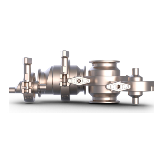
Summary of Contents for Dixon EHSC Series
- Page 1 Instruction & Operation Manual HSC and EHSC Series Spring Check Valves Read and understand this manual prior to installing, operating or servicing this equipment. Effective Date June 2019...
-
Page 2: Table Of Contents
Table of Contents ..................................Safety Care of Stainless Steel ................................5 Technical Specifications ..............................6-7 Installation and Start-Up ..............................8-9 Unpacking ..................................…8 Tools Needed ................................…8 Welding ..................................…8 Function Testing ..................................…9 Orientation ................................... …9 Cleaning ....................................10 General Maintenance ................................. -
Page 3: Safety
Safety labels are placed on equipment where appropriate. Do not remove any labeling from any piece of equipment. Replace any label that is missing. DO NOT modify any Dixon Sanitary product. Non-factory modifications could create hazardous conditions and void all warranties. DO NOT attempt to use a Dixon Sanitary product in any application that exceeds the product rating. - Page 4 Safety Information Owner Must Ensure • The product is only used as authorized. • The product is only used when it is in fault-free, fully functional condition, and that the safety equipment is regularly checked to ensure that it is fully functional. •...
-
Page 5: Care Of Stainless Steel
Care of Stainless Steel The stainless-steel components in Dixon Sanitary equipment are machined, welded and assembled by skilled craftsmen using manufacturing methods that preserve the corrosion-resistant quality of the stainless steel. Retention of corrosion-resistant qualities under processing conditions requires regular attention to the precautions listed below. -
Page 6: Technical Specifications
Technical Specifications Materials of Construction Technical Data • product contact components: 316L stainless steel • non-product contact components: CF8 Sealing Materials Technical Data • product contact components: FKM or EPDM Line Pressure Technical Data • max product line pressure: 145 PSI (10 bar) Product Temperature Technical Data •... - Page 7 Pressure Drop Charts HSC & EHSC Series Spring Check Valves 0.5 inch - 0.75 inch 0.50" 0.75" FLOW RATE (GPM) 1 inch - 4 inch 1.0" 4.0" 2.5" 2.0" 1.5" 3.0" 75 100 125 150 175 200 225 250 275 300 325 350 375 400 425 450 475 500 FLOW RATE (GPM) dixonvalve.com •...
-
Page 8: Installation And Start-Up
Installation & Start-Up The following should be performed upon receiving the product and prior to installation and use of the product. It is important that all the following processes and procedures are carefully followed and adhered to. Dixon ® is not responsible for any damage that occurs during the unpacking or installation process. -
Page 9: Function Testing
Installation & Start-Up Function Testing The information provided in this manual is intended to be used as a guide for proper functionality. Before installation, test the equipment under the specific conditions of the application in a safe, controlled environment. Variations in application conditions can cause equipment to fail, even though it passed an initial test. -
Page 10: Cleaning
Cleaning IMPORTANT: Before operating the equipment during formal production, please follow the guidelines listed below to ensure that your equipment is clean and ready for service. • Ensure that the equipment is installed in a proper orientation to allow the equipment to be cleaned and drained properly. -
Page 11: General Maintenance
General Maintenance To ensure proper operation of your Dixon ® equipment, proper maintenance must be performed at regular intervals. To prevent damage, check all fitting connections and screw connections for any loosening of the connections during equipment operation. Maintain adequate spare parts stock for all replacement components on the piece of equipment. Please refer to the repair kits section of the manual for complete component part numbers and kit part numbers. -
Page 12: Inspection
General Maintenance Inspection Inspection of all components listed below should be done during regular servicing intervals. Before removing the equipment from the process line, please take care to do the following: • Clean the process line completely to remove any product that may be harmful if contacting a person. •... -
Page 13: Assembly And Disassembly
Assembly and Disassembly For disassembly, follow the appropriate assembly instructions, in reverse. To ensure quality operation of your Dixon ® equipment, the equipment must be disassembled and assembled properly to prevent equipment damage during operation. Please follow the instructions contained in this manual carefully and be sure to follow any safety warnings contained herein. - Page 14 All images shown are for illustration purposes only. Actual product may vary due to differences between size and series. Place spider O-ring, spider plate, and body Install plunger O-ring onto plunger and set gasket onto upper body. Ensure proper into lower body. Slide spring onto plunger. orientation of spider plate.
- Page 15 Assembly (1 inch – 4 inch HSC | 1.5 inch – 4 inch EHSC) All images shown are for illustration purposes only. Actual product may vary due to differences between size and series. Install plunger O-ring onto plunger and set Set body gasket onto lower body.
-
Page 16: Repair Kits
To prevent damage ® and improper operation, use only genuine replacement parts and kits offered by Dixon to maintain the integrity of the equipment. Make sure the parts are properly matched to the series, model, serial number and revision level of the equipment. Please see the list of kits... -
Page 17: Bill Of Materials
Bill of Materials ITEM PART NO. DESCRIPTION MATERIAL QTY. 0.5 INCH CONCENTRIC SPRING CHECK VALVE HSC-LB050 LOWER BODY 316L SS -PART OF REPAIR KIT- HSC-P050 PLUNGER 316L SS HSC-SP050 SPRING -PART OF REPAIR KIT- HSC-S050 SPIDER 316L SS -PART OF REPAIR KIT- 13MHHM100-150 CLAMP HSC-UB050... - Page 18 ITEM PART NO. DESCRIPTION MATERIAL QTY. 0.5 INCH ECCENTRIC SPRING CHECK VALVE HSC-LB050 LOWER BODY 316L SS -PART OF REPAIR KIT- HSC-P050 PLUNGER 316L SS HSC-SP050 SPRING -PART OF REPAIR KIT- HSC-S050 SPIDER 316L SS -PART OF REPAIR KIT- 13MHHM100-150 CLAMP EHSC-UB050 UPPER BODY...
- Page 19 ITEM PART NO. DESCRIPTION MATERIAL QTY. 1 INCH ECCENTRIC SPRING CHECK VALVE HSC-LB100 LOWER BODY 316L SS -PART OF REPAIR KIT- HSC-P100 PLUNGER 316L SS HSC-SP100 SPRING -PART OF REPAIR KIT- 13MHHM100-150 CLAMP EHSC-UB100 UPPER BODY (2 PC) 316L SS dixonvalve.com •...
- Page 20 dixonvalve.com • 800.789.1718 HSC & EHSC | IOM...
- Page 21 ITEM PART NO. DESCRIPTION MATERIAL QTY. 1 INCH - 4 INCH CONCENTRIC SPRING CHECK VALVE HSC-LB100 1 INCH LOWER BODY, CLAMP HSC-LB100B 1 INCH LOWER BODY, WELD HSC-LB150 1.5 INCH LOWER BODY, CLAMP HSC-LB150B 1.5 INCH LOWER BODY, WELD HSC-LB200 2 INCH LOWER BODY, CLAMP HSC-LB200B 2 INCH LOWER BODY, WELD...
- Page 22 ITEM PART NO. DESCRIPTION MATERIAL QTY. 1.5 INCH - 4 INCH ECCENCENTRIC SPRING CHECK VALVE HSC-LB150 1.5 INCH LOWER BODY, CLAMP HSC-LB150B 1.5 INCH LOWER BODY, WELD HSC-LB200 2 INCH LOWER BODY, CLAMP HSC-LB200B 2 INCH LOWER BODY, WELD HSC-LB250 2.5 INCH LOWER BODY, CLAMP 316L SS HSC-LB250B...
-
Page 23: Dimensions
Dimensions Dimensions are approximate and subject to change without notice. Contact sanitarydrawings@dixonvalve.com for specific drawing related requests. EHSC A (inches) Size EHSC 0.5 inch 0.75 inch 1 inch 1.5 inch 2 inch 2.5 inch 3 inch 4 inch dixonvalve.com • 800.789.1718 HSC &... -
Page 24: Model Numbers And Part Numbers
– options that meet your specific requirements. If you require an option that is not listed in this key, please feel free to contact Dixon ®... -
Page 25: Troubleshooting
Check installation section to make sure fluid is flowing Fluid not flowing through valve Valve is installed improperly into inlet of valve Any other issue Contact Dixon Sanitary 800.789.1718 dixonvalve.com • 800.789.1718 HSC & EHSC | IOM... -
Page 26: Certifications
Certificates Dates shown on certificate may not be current. dixonvalve.com • 800.789.1718 HSC & EHSC | IOM... -
Page 27: Warranty
DIXON VALVE AND COUPLING COMPANY (herein called "Dixon") warrants the products described herein and manufactured by Dixon to be free from defects in material and workmanship for a period of one (1) year from date of shipment by Dixon under normal use and service. - Page 28 Dixon, founded in 1916, is a premier manufacturer and supplier of hose couplings, valves, dry-disconnects, swivels, and other fluid transfer and control products. The company’s global reach includes a wide range of products for numerous industries including petroleum exploration, refining, transportation, chemical processing, food &...
Need help?
Do you have a question about the EHSC Series and is the answer not in the manual?
Questions and answers