Table of Contents
Advertisement
Quick Links
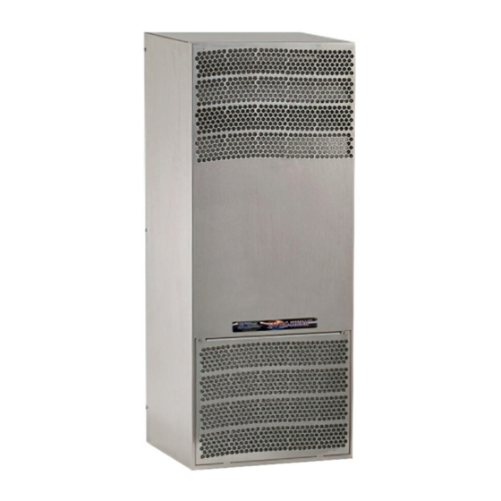
Table of Content SCE-AC2550B120VSS
..................................................................................................................................
..............................................................................................................................
.....................................................................................................................................
Version Nr. 1-5 - 03.09.2019
.........................................................................................................................
......................................................................................................................
.....................................................................................................................
.....................................................................................................................
.....................................................................................................................
.............................................................................................................
...............................................................................................................
.........................................................................................................................
..............................................................................................................
......................................................................................................................
.........................................................................................................
................................................................................................................
..........................................................................................................................
Doc. Nr. 9957081182SG
2
2
3
4
8
9
10
11
12
13
13
14
14
14
15
15
1 / 15
Advertisement
Table of Contents

Related Manuals for SCE SCE-AC2550B120VSS


Summary of Contents for SCE SCE-AC2550B120VSS
-
Page 1: Table Of Contents
Table of Content SCE-AC2550B120VSS 1. User manual ..........................2. Legal regulations ......................... 3. Safety instructions ........................4. Controller functions ........................5. Functional principle ........................6. Technical data ..........................7. Mounting ............................. 8. Mounting Principle ........................9. Dimensions (H x W x D) ...................... -
Page 2: User Manual
1. User manual This instruction manual contains information and instructions to enable the user to work safely, correctly and economically on the unit. Understanding and adhering to the manual can help one: Avoid any dangers. Reduce repair costs and stoppages. Extend and improve the reliability and working life of the unit. -
Page 3: Safety Instructions
Disregarding the instruction manual Operating error Inappropriate work on or with the unit The use of non-specified spare parts and accessories Unauthorised modifications or changes to the unit by the user or his personnel The supplier is only liable for errors and omissions as outlined in the guarantee conditions contained in the main contractual agreement. -
Page 4: Controller Functions
4. Controller functions The cooling unit is intended to be used as a complementary accessory to larger industrial equipment. The unit is used where heat needs to be dissipated from electrical control cabinets or similar enclosures in order to protect heat sensitive components. It is not intended for household use. The unit has two completely separate air circuits which ensure that the clean cabinet air does not come into contact with the ambient air which may well be dirty or polluted. - Page 5 Setting cooling set point, St1: 1. Press “SET” and display should show St1 and then the pre-set value of St1. (default: +35°C / +95°F) 2. Reach the desired value by using ▲ or ▼. 3. Press “SET” again to save the new value of St1. Setting heating set point, St2 (only for units supplied with internal heater): 1.
- Page 6 Test function Different test functions can be used depending on the combination of keys pressed. Such tests run for the duration of 4 minutes. “SET+▲” tests Compressor and Ambient Blower relays. “SET+▼” tests Alarms and Heater relays Alarm Relay Operation Both normally closed (NC) and normally open (NO) alarm contacts are provided.
- Page 7 Important Notes Whilst programming, if no button is pressed for 10 seconds, the display starts flashing, and after 1 minute returns to the main display without saving changes. To increase scrolling speed, press and hold the ▲ or ▼ button for at least 5 seconds. When pressing “PRG”...
-
Page 8: Functional Principle
5. Functional principle The cooling unit for enclosures works on the basis of a refrigeration circuit consisting of four main components: compressor (1), evaporator (2), condenser (3) and expansion device (4). The circuit is hermetically sealed and R134a refrigerant circulates inside it (R134a is chlorine free and has an Ozone Destruction Potential [ODP] of 0 and a Global Warning Potential [GWP] of 1430). -
Page 9: Technical Data
6. Technical data Order Number SCE-AC2550B120VSS Cooling capacity L35L35 2550 BTU Cooling capacity L35L50 1740 BTU Heating capacity 400 W Compressor Reciprocating compressor Refrigerant / GWP R134a / 1430 Refrigerant charge 234 g / 8 oz 25 / 6 bar... -
Page 10: Mounting
7. Mounting Always disconnect the power supply before opening the unit. The heat load to be dissipated from enclosure should not exceed specific cooling output of the unit at any condition. At cooling unit selection always cater for a safety margin of at least 15% extra cooling output in the worst conditions. -
Page 11: Mounting Principle
8. Mounting Principle M6 bolts M6 toothed washers M6 Flat washers Enclosure Mounting gasket Cooling unit Version Nr. 1-5 - 03.09.2019 Doc. Nr. 9957081182SG 11 / 15... -
Page 12: Dimensions (H X W X D)
9. Dimensions (H x W x D) Version Nr. 1-5 - 03.09.2019 Doc. Nr. 9957081182SG 12 / 15... -
Page 13: Electrical Connection
10. Electrical connection Door Switch The unit can be switched on and of via a door contact switch. When delivered the door contact terminals are bridged on the female connector. To connect the door contact switch remove the bridge and connect door contact switch. -
Page 14: Taking Into Operation
12. Taking into operation Attention! The unit can be damaged by lack of lubricant. To ensure that the compressor is adequately lubricated the oil, which has been displaced during transport, must be allowed to flow back into it. The unit must therefore be allowed to stand for at least 30 min. -
Page 15: Transport & Storage
1 x Female connector with shorted wired positions for door contact Saginaw Control and Engineering 95 Midland Road Saginaw, MI 48638 Phone: 989 / 799-6871 Fax: 989 / 799-4524 sce@saginawcontrol.com Version Nr. 1-5 - 03.09.2019 Doc. Nr. 9957081182SG 15 / 15...
Need help?
Do you have a question about the SCE-AC2550B120VSS and is the answer not in the manual?
Questions and answers