
Summary of Contents for REDT R&D MAGIC-70
- Page 1 R&D by REDT http://www.redt-magic-engraver.com 3F, (1314 Gwanpyeong-dong) 13-10, Techno 2-ro, Yuseong-gu, Daejeon, Republic of Korea, 305-709 TEL: +82-70-7011-0905 FAX: +82-42-673-0905...
-
Page 2: Table Of Contents
Contents Cautions for Use Product Parts and Installation 1) Parts and Accessories ..................5 2) Specifications ..................... 7 3) MagicArt S/W Program Installation ..............8 4) MAGIC-70 Installation ..................10 5) Description of MAGIC-70 ..................11 6) How to Use the Clamp ..................18 7) Changing Tools .................... - Page 3 Import a File in SVG Type Origin Point Calibration 1) Tool Calibration (touch) ...................117 2) Probe Calibration ....................119 3) Laser Pointer Calibration ................120 4) Saving Multi-performance Clamp Origin Position .......... 124 5) Saving New Clamp Origin Position ..............125 6) Chuck Finger Origin point ................
-
Page 4: Cautions For Use
Cautions for Use Please be sure to read and follow the instructions below for safety use. The instructions below are intended to prevent personal injury and property damages. Please read carefully and use the machine properly. If you don’t follow these instructions, injury or property damage may occur. If you don’t follow these instructions, users may be seriously injured. - Page 5 Cautions related to use Do not allow any part of body or Do not put water or small metal other objects onto the engraver. materials on the engraver. The cutter of engraver may Due to negligence or vibration cause serious injury during its of the engraver, the materials operation.
-
Page 6: Product Parts And Installation
Product Parts and Installation 1) Parts and Accessories MAGIC-70 product box includes the engraver and following accessories. Accessories Photos Purpose Tool for engraving. And ring outer diameter Diamond tip (4Φ) engraving. (Spindle) Tool for engraving. And ring inner diameter Diamond tip (3.175Φ) engraving. - Page 7 Jig for holding rings when engraving ring’s Flat chuck finger outer diameter or inner diameter of flat rings. Round chuck Jig for holding rings when engraving ring’s finger inner diameter. (Wide width) Round chuck Jig for holding rings when engraving ring’s finger inner diameter.
-
Page 8: Specifications
※Optional(Separately purchased) Flat clamp For holding material in place. 2) Specifications Power supply 100~220V Consumption voltage Operating range Flat : 140mm(X) x 100 mm(Y) x 38.5mm(Z) Rotary: (X) Cylinder outside diameter: Max.93mm Cylinder inside diameter: Min.13mm~Max.93mm Resolution 0.005mm (X,Y), 0.00125(Z) Weight 31.15Kg 9,000~15,000 RPM... -
Page 9: Magicart S/W Program Installation
3) MagicArt S/W Program Installation Place the CD in your computer`s CD driver, Follow the below instructions to install the S/W. Install program will be automatically executed and program installation will be progressed in the following order. If Install program is not automatically executed after CD is entered, execute Install program on My Computer’s CD drive. - Page 10 ◈ Program description Once the program is installed, the icon below will be created on the desktop. The description of the icon is as follows. This is software for design and engraving with features like engraving contents design, tool path creating and tool path data transfer. ◈...
-
Page 11: Magic-70 Installation
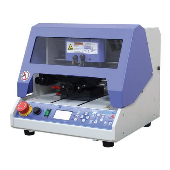
4) MAGIC-70 Installation MAGIC-70 is a desktop CNC(Computerized Numerical Control) engraver. This engraver cannot be operated independently. You need your machine to be connected to a PC and run with a provided program, in order to reform engraving work as you want. Insert the provided USB cable into the port on the rear side of the engraver and the USB port of your computer respectively. -
Page 12: Description Of Magic-70
5) Description of MAGIC-70 ◈ Parts ◈ Description of each part Spindle Tightens an engraving tool. Probe Measures a height of engraving material. Tool Length Sensor Measures the height of tool. Pen Clamp Adapter Inserts and holds a pen clamp. Multi performance Clamp Fix the material in place. - Page 13 Communication port Connects USB cable to the computer.
- Page 14 ◈ Description on Keys Once this button is pressed during engraving, all operations STOP in progress will stop. If you press and hold the button, it enters into tool settings VISE mode. If you lightly press the button, the clamp moves back and forth.
- Page 15 CLAMP Moves the Multi-performance clamp. RING OUTER Moves the ring outer diameter engraving position of the DIAMETER rotating clamp. RING INNER Moves the ring inner diameter engraving position of rotating DIAMETER clamp ◈ Engraver movement When the engraver is turned on, the engraver begins the self-test in the following order, and it enters into waiting mode with confirmation sound if there is no problem.
- Page 16 ◈ Description on Menu If press the button, entering to the menu mode. It is same function of operation keys. Press and hold the button for more than 3 seconds to enter each menu. Exchange the tools. Check XY coordinate. ※If the machine is restarted, set value is reset.
- Page 17 ON 5V output of the machine. ※ The port on the backside of machine can output 5V. It can control the power of buzzer, vacuum device, etc. Select the language. Select the calibration mode. 1. Origin No: 0(Center)~8 User can set and save your own origin. 2.
- Page 18 ◈ Measurement Select User can select measurement mode within two seconds before measurement begins, after transferring tool path (engraving data) from MagicArt to the machine. : Select Measurement Mode : Select Probe/Touch Measure the origin of engraving area. Measure the beginning point. Measure whenever tool moves and meet the material.
-
Page 19: How To Use The Clamp
6) How to Use the Clamp ◈ Multi performance Clamp The holding part of clamp is step type, so set the clamp to the step to match the size and thickness are matched. If you turn the clamp handle to the left, then the clamp will be loosed and turn it to the right, then the clamp will be tightened. - Page 20 ◈ How to attach the auxiliary jig The auxiliary jig helps to hold thick materials like a beer bottle. As a pair, the Auxiliary jigs are holed by bolts on each hole. ◈ Rotation Clamp(Chuck) -Holding method for outer diameter engraving Insert the ring until it clicks into the flat chuck finger and turn the chuck handle to hold the ring and not to allow it come out or spin.
- Page 21 -Holding method for ring inner diameter engraving Open the chuck finger of the rotation clamp and insert the ring, and use the chuck handle to hold it not to allow it to come out or slip. Ex) Flat chuck finger There are three types of chuck fingers.
- Page 22 If the thickness of ring is not even, mix different sized chuck fingers to hold it.
- Page 23 - Materials holding methods for engraving bracelets Place three bangle adapters in the rotation clamp, and tighten the chuck finger in front of the bangle adapters. Open the rotation clamp to match it to the bracelet size, and insert the bracelet until it clicks into the chuck finger. Use the chuck handle not to make bracelet come out or spin.
- Page 24 ◈ Cutting Clamp Release four tightening bolts on the cutting clamp, and insert the Bakelite plate. Put materials on the Bakelite plate and tighten with bolts. Open the clamp wide at the maximum, and put the clamp dedicated to cutting on it, and tighten it.
- Page 25 ◈ Flat Clamp ( Separately purchased) ※ Is secured on the base table by using 4 bolts at each corner of the clamp. 1. Turn the clamp knob on the left side of the clamp and pull the clamp and spacer block to take it out. 2.
-
Page 26: Changing Tools
7) Changing Tools ◈Spindle 1. Press button and go to the menu mode. 2. Press button, and when menu appears on the LCD window, then press and hold button until it beeps (more than 3 seconds) to run the menu. 3. -
Page 28: Replacing The Spindle Belt
8) Replacing the Spindle Belt The spindle belt transfers the rotation power of the spindle motor to the spindle to turn the engraving blade. If the spindle belt is worn, the surface is cracked and slippery. So it cannot deliver the power of the spindle motor properly. In this case, the number of rotation decreases, or it causes poor engraving quality. - Page 29 ◈ Pressure Adjuster When engraving with a Carbide tip, the engraving depth is adjusted with pressure. This is the using same as the engraving depth selection when creating the tool path. If you turn the tension adjustment knob to the right, the pressure increases stronger, and turning it to the left, decreases the pressure.
-
Page 30: Program Usage Description
Program Usage Description Run the program, then a window show up as below. The program window is different between when an object is selected and not selected. The names of parts for each case are as follows. ◈ Program screen Menu Template category Toolbar... - Page 32 ◈ Object selection mode After entering texts, click [Selection] button with a mouse or click the work area with mouse right button. Then, the entered character object is selected and it turns into selection mode. Double click mouse left button in the selection mode to convert it into character entering mode.
-
Page 33: Toolbar
1) Toolbar ◈ Alignment tools [Line/Curve] Click a certain point with the mouse and move it to make a dot line appear. Designate the distance and click with the mouse and then press the right button on the mouse to create a straight line. At this time, press “Ctrl” key on the keyboard and move the mouse to create a horizontal line or a vertical line. - Page 34 Determine the curvature of each edge on the rectangular object registration information or drag the rectangular edge with the mouse to transform it into a round rectangle with round corners. Click button on the rectangular object registration information and adjust the curvature of each corner individually. [Polygon] Click and hold the work area with the mouse and drag it to designate the size of a polygon.
- Page 35 [Vertical center in page] [Horizontal center in page] [Center in page] Align to the left of base object Align to the center of base object Align to the right of base object Alignment Align to the top of base object Align to the center of base object Align to the bottom of base object Adjust horizontal gap...
- Page 36 [Left top Origin point] [Left bottom Origin point] [Center Origin point]...
- Page 37 ◈Object tools [Template] Either import a template or save the currently selected object as a template. What is a template? Template is an image of materials to be engraved. The engraving is actually done as same as the design on the template. Template is not selectable by mouse, but you can select it by dragging it while pressing “Shift”...
- Page 38 [Selection] It is available either to select the object created in the work area to adjust its size and location or to change the object’s property. Only the selected objects are subject to changing their location/size/size and engraving. In the character input mode, converting to any selection mode easily by pressing the right button of the mouse. [Select object] [Select no object] [Text input]...
- Page 39 [Drawing pen] You can draw by dragging the mouse. The thickness of drawing line can be adjusted in the drawing object information window. [Image] Import image (bmp, jepg, gif, png … etc.) [Line eraser] Clear the line of object. Move the mouse over the line of object. The line will be removed (Some objects cannot be removed with the Clear line tool)
- Page 40 [Cutting tool path] Create a tool path that will engrave the selected object’s border. [Hatching tool path] Create a tool path that will engrave the inside of the selected object. [Single line tool path] Create a tool path that will engrave the center line of the selected object. [Text input engraving tool path] Create a tool path that will engrave the inside of the selected object with dots.
- Page 41 [Show tool path only] Only tool path is shown on the screen with temperately masking all of other objects. If this button is pressed once again, all objects will be seen again. [Instant engraving] Immediately engrave the selected object without creating a tool path. Select an engraving method from the engraving selection list on the Engrave window and select engraving options and measuring methods before clicking “Start Engraving”...
- Page 42 ◈ Basic tools [New document] Open a new file [Open] Import a file save in *.dgn. Select a file on the “Open” window and click “Open” button.
- Page 43 [Save document] Save the design drawn on program by ” *.dgn.” Chose the location (folder) in which the file will be saved and enter the file name before clicking “Save” button. [Print] Print the design drawn on program. [Cut] Cut the selected object. If Ctrl+X is pressed on the keyboard, the same function will be executed.
- Page 44 [Copy] Copy the selected object. If Ctrl+C is pressed on the keyboard, the same function will be executed. Ctrl + C Ctrl + V [Multiple paste] If more than one of the same object is needed, multi-copy the object in several constant gaps by clicking Edit menu →...
- Page 45 [Undo] Return the work recently done to its previous state. The number of undo stage can be adjusted with Tools → Option → General. Change font Undo [Redo] Re-execute the undone work. Change font Undo Redo...
- Page 46 ◈ Screen Zoom In/Out/Move Tools [Zoom in] The screen is zoomed in by one level. [Zoom out] The screen is zoomed out by one level. [Zoom in/Out ratio] If any screen ratio is selected, the screen in the size of the selected ratio will be seen.
- Page 47 [Magnifier] Drag a certain spot with the mouse to enlarge it. [Fit to object] Enlarge the selected object to make it filled with the screen. [Fit to page] Adjust the page size to see the whole work area. [Panning] Drag the screen with the mouse to move it.
-
Page 48: Registration Information Of Character Object
2) Registration Information of Character Object If any character object is selected, the registration information of character object will appear in the left of the screen. [Font] Designate font. Either click the font’s arrow or click Preview button to designate font. [Size] Adjust the size of the selected character size. - Page 49 [Bold] Change character style to bold. [Italic] Change the character style to italic. [Reduce or increase font weight by one level] Adjust the weight of font. [Symbol] Insert symbols.
- Page 50 [Text change] The entered text of the selected object can be displayed and changed. Press button to change the text more easily. Align characters to the left in the text box. [Align to left] Align characters to the center in the text box. [Align to center] Align characters to the right in the text box.
- Page 51 Align characters to the top in the text box. [Align to top] Align characters to the center in the text box. [Align to center] Align characters to the bottom in the text box. [Align to bottom] Arrange characters horizontally. [Horizontal text ] Arrange characters vertically.
- Page 52 Rotate the selected character. Location of the selected object Size of the selected object Line thickness of the selected object Line type of the selected object Line color of the selected object Color filled inside of the selected object Type of filled inside of the selected object...
-
Page 53: Registration Information Of Rotation
3) Registration Information of Rotation Rotate the selected object by one degree. Enter the desired angle of rotation, and press button, then the object is rotated by the angle you enter. Rotate the selected object at the same degree as entered. Rotate and add a new object at the same degree as entered... -
Page 54: How To Engrave For Each Tool Path
4) How to Engrave for Each Tool Path [Content] Engrave the border of characters. Engrave the inside of characters. Cutting Hatching Engrave the surface of characters Engrave the center of characters. character with dots. Single line... -
Page 55: Create Tool Path
5) Create Tool Path Hatching gap, depth, engraving speed and others are pre-set for each engraving option. Therefore, it is not necessary to designate hatching gap, Preset depth, engraving speed and others every time and they will be automatically set with their pre-set values. Each engraving option value can be changed by pressing Edit or Add button on the Set engraving option window. - Page 56 If engrave border is cancelled, a tool path will engrave only the inside of the character created. Engrave outline When moving to another engraving location, it is necessary to lift Z axis to Z Clearance prevent the tool from contacting with the material surface before moving. For this, designate the height to be applied at this time.
-
Page 57: 5-1) Engraving Option: Add/Delete/Edit
5-1) Engraving Option: Add/Delete/Edit If Select engraving option is checked, Add/Delete/Edit buttons will appear. Enter a name to the engraving option setting window and designate hatching gap, engraving depth and speed before clicking “OK” button. They will be added to the engraving option selection list. Select an option to be deleted and click “Delete”... -
Page 58: 5-2) Add/Delete/ Edit Tool
5-2) Add/Delete/ Edit Tool If “Edit” button is checked, Add/Delete/Edit button will appear. Designate the name of a tool to be added along with its type, end width and click “OK” button. The tool will be added to the tool selection list. Select a tool from the list and click “Delete”... -
Page 59: Registration Information Of Tool Path
6) Registration Information of Tool path If tool path object is selected, the registration information of tool path window will appears in the left of the screen to allow the user to adjust its depth and speed once again. Engraving: It does not mean the actual engraving depth but refers to “Applied pressure”... -
Page 60: Transfer Nc Data
7) Transfer NC data Transfer the selected tool path to the engraver. Select a tool path object and click button to make the transfer NC data window appear. Select a measuring method and click “Start engraving” button. Measure material height only. Surface height Measure material’s horizontal gradient. - Page 61 Measure material height. Surface height Multi point Measure material height by dividing the whole material into several parts(up measurement to 5 times) Outside Engrave on the ring’s outer diameter. Inside Engrave on the ring’s inner diameter. Place the material to the flat chuck finger. Place the material to the round chuck finger.
-
Page 62: Engraving Process
Engraving Process Tool: Tip Clamp: Multi performance clamp 1. Measure material to be engraved Vertical Horizontal 2. Fix a material to be engraved to the center of clamp 3. Select the template the most similar to the material to be engraved from the template category and enter the size of the material before clicking “OK”... - Page 63 4. Once the template appears, press [Text input] and click any wanted location with the mouse to enter characters. 5. Once entering characters is completed, press toolbar’s [Selection] and go to the select object mode to select the entered characters. Then, edit the size, font and thickness of the object. If you want to allocate the object at the center of the work area, click [Center in page] button.
- Page 64 6. Once the design is completed, click [Hatching tool path]. A tool path means a route along which a tool is moved for engraving. 7. Select an engraving option and tool from “Hatching tool path” window and if necessary, designate gap and depth before clicking “Create tool path”...
- Page 65 8. “Tool path” object is created. 9. Click [Engraving] button. 10. Once “Output” window appears, specify how to measure the engraving materials. And then, click “Start engraving” button.
- Page 66 11. Once the tool is moved to the center of the material and stopped, the engraving area can be verified and adjusted by using the direction key button. At this time, check the laser pointer while moving it for easier measurement and adjustment.
- Page 67 select probe, Measure the beginning point. “Measure the origin of engraving area” mode is Measure whenever tool moves automatically selected and meet the material. and the others cannot be ※ “Z Clearance” should be set selected. enough large value when setting the tool path to avoid damage material.
-
Page 68: Engraving Process Of Ring Inner/Outer Diameter
Tool: Tip Clamp: Rotation clamp 1. Measuring the width and diameter of a ring to be engraved. Width Diameter 2. Insert the ring into the chuck finger as below, and tighten the rotation clamp to set it. Outer diameter Inner diameter Since the character engraving direction is as shown in the picture below, check out the direction of the materials and set it. - Page 69 ◈ Ring (Bangle) Outer Diameter 1. Press button on the engraver. A message requiring removal of the clamp appears on the screen. ※ Proceeding without removing the clamp, a damage may occur in the clamp and other tools. 2. Remove the clamp by loosening the clamp tightening lever. 3.
- Page 70 ◈ Ring (Bangle) Inner Diameter Use an L-tool to engrave ring or bangle inner diameter. 1. Press button on the engraver. A message requiring removal of the clamp appears on the screen. 2. Remove the pendant clamp by loosening the clamp tightening lever. 3.
- Page 71 5. Adjust the height of L-tool to get a proper height for the engraving. With the L-tool at a proper height, fix it with the L-tool tightening bolts. Bangle inner diameter Ring inner diameter The length of the L-tool fixture should be flexible to meet the shape of the bangle. Please fix L-tool properly to the shape of the bangle.
- Page 72 ◈ Program Process 1. Double click “Ring” template in the object registration information. 2. When “Insert Rotary Object Template” window appears, enter the width and diameter of the ring measured and click “OK.”...
- Page 73 3. The template appears at the center of the screen. 4. Select [Text Input] from the menu, and click the work area using mouse and enter the characters to be engraved.
- Page 74 5. After entering characters, press [Selection] in the toolbar to enter the object selection mode. Select the character string, and edit the size and font of the object. If you want to place the object at the center of the work area, click [Center in Page] button.
- Page 75 7. Once “Hatching Tool path” window appears as shown in the picture below, select tool, tool path gap and depth, and click “Create Tool Path” button. 8. The “Tool path” object is created as below and marked with red line on the screen. Turn the mouse wheel to enlarge the tool path object, and if it is not the tool path you want, delete the tool path and extract it again by adjusting the extraction option.
- Page 76 9. After selecting a tool path, click 10. Once “Transfer NC data” window appears, specify Communication port and rotation clamp option. And then, click “Start Engraving” button. Measure material height. Surface Height Multi point Measure material height by dividing the whole material into several parts(up Measurement to 5 times) Outside...
- Page 77 11. Once the tool is moved to the center of the materials and stopped, the engraving area can be verified and adjusted by using the direction key button. At this time, check the laser pointer while moving it for easier measurement and adjustment.
-
Page 78: Character Cutting Process
Character Cutting Process Tool: Endmill Cutter Clamp: Cutting clamp Other: Apply cutting oil on the surface of materials to improve engraving quality and extend the lifespan of Cutter Replace the tool with a cutting tool, and press the tool exchange button to measure the tool depth. Also, be sure to set the head by tightening the engraver pressure lock. - Page 79 want and enter the characters. 4. After entering characters, press [Selection] in the toolbar to select character string and designate the font. Adjust the character to the size you want. Adjust the size by using an object handle as below, or adjust the size from the left object registration information window.
- Page 80 5. Drag the character gap adjustment handle (a square in the picture below) with the mouse to narrow the gap between the characters. Adjust character gap If the gap of some characters is partially adjusted, press [Text Input] button and drag the mouse to select what you want.
- Page 81 7. Once the “Cutting Tool path” window appears as seen in the figure below, select cutting depth (material thickness + 0.1~0.2mm) and tool diameter and click “Create tool path.” Designate the thickness for cutting. Since material may be bent or slanted, the Depth depth should be 0.1-0.2 mm deeper than the thickness for perfect cutting.
- Page 82 8. “Tool path” is created. 9. Click button. 10. Once “Output” window appears as seen in the figure below, specify how to measure Communication port and material. And then, click “Start engraving” button. How to measure a material...
- Page 83 Measure material height only. Surface Height Measure material’s horizontal gradient. Horz. Slope Measure material’s top, bottom, left and right gradient. Surface Slope Do not measure its height. In this case, the height previously measures can Skip be used. If the material is not removed from the clamp during the previous engraving work, the measuring time can be saved with this option.
- Page 84 11. If the tool is moved to the center of the material and stopped, the engraving area can be verified and adjusted by using the direction key button. At this time, check the laser pointer while moving it for easier measurement and adjustment.
-
Page 85: Engraving By Using Nose
Engraving by Using Nose Nose is a sub-component to support engraving along with the curved surface of material. Therefore, it is possible to engrave on the curved surface of material with consistent depth by using the nose. Tool: V cut tool Clamp: Multi performance clamp, Rotation clamp Be sure to release the engraver pressure lock. - Page 86 It might be difficult to adjust the tool length if the nose height adjustment screw set to the top, so separate it about 1~2mm from the head. Head 1~2mm Nose height adjustment 3. Assemble the nose height adjustment screw with the nose and turn the assembly to the right to make the nose’s tool hole locate before the tool tighten bolt.
- Page 87 6. Rotate and tighten the depth nose lock to the right not to make the nose height adjustment screw loosened. If the depth nose lock is not fixed, the nose height adjustment screw might be loosened to change the engraving depth or cause damage to the material, tool or nose. 7) Changing Tools 7.
-
Page 88: Drilling
Drilling What is Drilling? It drills a hole with certain depth and diameter on materials by using endmill or V-cut tool. Depending on the tool thickness, the whole size becomes different sizes. Be sure to fix the engraver pressure lock. If the head is not fixed, the drilling may not be the designated depth. - Page 89 The drilling tool path object can be copied and used in several constant gaps by using Edit menu → Copy → Multiple-copy. Drag and move a drilling object with the mouse to drill it into various shapes.
- Page 90 ◈ Fill Inside Object with Drilling Position Select a shape to be filled with the drilled object. Click “Insert → Drill → Fill Inside Object with Drilling Position …”. Select a tool to be used on the Auto create drilled object window and adjust options such as depth, speed, gap etc.
- Page 91 ◈ Layout Drilling Position along Line The drilled object along can be allocated along the outline of the selected the object. Select a line on which the drilled object is automatically allocated. Click Insert → Drilling (beta) → Layout Drilling Position along with Line...
-
Page 92: Image Engraving
Image Engraving What is image engraving? This is an engraving method to express the shade of image with dots. Tool: Tip Clamp: Multi performance clamp 1. Attach a material to be engraved to the clamp. 2. If [Image] button is clicked, open window will appear. Import the image to be engraved. 3. - Page 93 4. Click [Text Impact Engraving Tool path] button. 5. Adjust image engraving option in punching option window. When engraving an image, bright part (white area) of image can be expressed by punching. Since darker image shows higher quality, adjust the brightness to dark. Normally, dot ratio 10-20% shows the best engraving quality for a portrait.
- Page 94 6. Click “OK” button to create tool path for image engraving. After checking the tool path, click “Engraving” button. When engraving an image, white area of image is punched. So the result of the tool path is shown as negative image. 7.
-
Page 95: Pen Engraving Process
Pen Engraving Process Tool: Tip Clamp: Pen clamp, Rotation clamp 1. Measure the width and diameter of the pen to be engraved. Diameter Width 2. Set the pen in the engraver by using a pen clamp. 3. Select pen template in the object registration information, and enter the width and diameter of the pen, and click “OK”... - Page 96 4. Once the template appears, press [Text Input] on the toolbar. Click the work area with the mouse and enter texts. 5. After texts are entered, press [Selection] on the toolbar to enter object selection mode. After selecting entered character string, adjust the size and font of the object. If you want to place the object at the center of the work area, click [Center in Page] button.
- Page 97 6. Once the design is completed, click [Hatching Tool path]. A tool path means a route along which a tool is moved for engraving. 7. Select engraving option and tool from the “hatching tool path” window, and designate hatching gap and depth when necessary and click “Create tool path”...
- Page 98 8. “Tool path” object is created. Click button. 10. Once “Output” window appears, specify how to measure engraving material. And then, click “Start engraving” button. 11. Designate the location for engraving then press and hold button until it beeps (more than 3 seconds) to start the engraving.
-
Page 99: Curved Materials Engraving
Curved Materials Engraving In case of bent materials, it may scratch the surface of materials after engraving lower part. 1. Enter the thickness of curved surface to be engraved to automatically set up the Z moving height. Create a tool path and Click [Engraving] button. -
Page 100: Entering Characters Placed In A Circle
Entering Characters placed in a Circle You can engrave by placing characters in a circle on round shape materials. There are two types – circler placed characters and roundly placed characters in double layer. You can choose either one. [Circular Text] Click button to display the characters to be placed in a circle window. - Page 102 [Circular Text(Top/Bottom)] Click button, then characters placed in a circle window appears. Enter the size of outer line and inner line, and texts, and click “OK” button. Adjust character angle Drag the first character [R] or last character [y] in the character string to adjust the angle of character string. Drag with mouse Drag other characters with mouse to adjust the distance to the center of character string.
-
Page 103: Entering Characters In A Curve
Entering Characters in a Curve 1. Click the [Line/Curve] button. 2. Click on a certain point with the mouse and designate a distance. Drag while clicking and holding the mouse to make a curve appear. Press the right button on the mouse to create the curve. [Mouse drag] 3. -
Page 104: Preview Font
Preview Font Apply the fonts installed on the computer to the character string and preview the shape to select the font you will use. After entering characters, click “Preview” button in the object registration information window or click mouse right button, and click “Font preview.” Then, “Font preview” window will appear. If you drag the font list in the font preview window, or click a font while pressing “Ctrl”... -
Page 105: Change Texts
Change Texts You can change the contents of design sample you frequently use. Import a saved design sample or file, or select an object designed on the screen. Click [Text change] button or click mouse right button to click “Text change”. Change contents in the “Text change”... -
Page 106: Create Template
Create Template Template is an image corresponding to the materials to be engraved by 1:1 ratio. Load a template most similar to the materials to be engraved, and enter the texts to be engraved. This way allows you to create the location of engraving and the size of texts to be engraved more easily and conveniently. - Page 107 [Add template2] 1. Press [Image] button to import a picture file and save the size of image. 2. Click [Template] button to show “Template Library” window. Click the template list window with mouse right button, and click “Save Selected” button. Enter new template name, and click “OK”...
-
Page 108: Saving As Design Sample
Saving as Design Sample Save the edited contents in Magic Art as design sample. You can use this whenever necessary. [Save 1] 1. Enter the contents, and adjust the font and size as desired. Select the object and click “save” from “file → Save As Design Sample”. - Page 109 [Save 2] 1. Select a designed object, and click [Design Sample] button. 2. Select the folder where the object is saved from the design sample library window. Click the mouse right button, and click “Save selected” button. Enter the name to be saved, and click “OK” button to save it in the design sample library.
-
Page 110: Auto Change Of Serial Number
Auto Change of Serial Number Use this function when you change numbers by certain unit. Edit the font and size of character, and press “Alt+N” key on a keyboard, or click “Text → serial number → Advance Serial Number” to change the number automatically. Click “Text →... - Page 111 Import serial number function can only import file separated by comma (.csv) or text file (.txt). Each row of the file will be recognized as one serial number, and the contents of each row separated by comma will be shown with linebreaks.
-
Page 112: Add And Edit Picture
Add and Edit Picture 1) Add picture This program provides a function to edit various types of picture files. Supported picture file types are as follows. Windows or OS/2’s bitmap graphic file CompuServe graphic file JPG/JPEG JPEG bitmap graphic file Portable Network Graphics bitmap graphic file Z Soft PC paintbrush bitmap file TIF/TIFF... - Page 113 3. Drag the work area by the mouse and decide picture size to load the picture.
-
Page 114: Convert And Edit Picture File
2) Convert and edit picture file Only single color image can be engraved. Since color image cannot be engraved by this engraver, it should be converted to single color (1 bit) image. [Convert single color image] 1. Select the image object you want to convert using mouse, and click “Transform” → “Bitmap” → “Mode” → “Monochrome (1bit)…”... - Page 115 [Edit image] Loaded image can be edited by third party program (picture edition). Select the image to be edited, and click mouse right button. Click “Edit” button or select “Bitmap” → “Edit...” from “Transform." Then, third party program (Paint) shows the image. After editing it, press “Save” from the file menu, and close the third party program (Paint) to apply the edition.
-
Page 116: Import A File In Svg Type
Import a File in SVG Type Magic Art supports vector graphic (SVG) files. So files saved as SVG type can be imported. If you save a design as SVG type from design program Illustrator or CorelDraw, you can import the file to the Magic Art. 1. - Page 117 3. Click “File” → “Import” button from the Magic Art menu to import a file.
-
Page 118: Origin Point Calibration
Origin Point Calibration ※ The machine is initially set up at factory. Please contact reseller before changing the machine settings. ※ Calibrate the machine by using tip(Carbide, Diamond). The machine cannot be calibrated by using endmill, cutter, etc. ※ Calibrate the machine while Engraver pressure lock is not fixed. The nose, tool, and material can be damaged if you calibrate the machine while the head is fixed. -
Page 120: Probe Calibration
2) Probe Calibration 1. Fix a material of flat surface on the clamp. 2. Press the button and go to the expert menu mode. 3. Press button, and when menu appears on the LCD window, then press and hold button for more than 3 second until it beeps (more than 3 seconds) to run the menu. 2.Probe 4. -
Page 121: Laser Pointer Calibration
3) Laser Pointer Calibration ◈ Spindle 1. Fix a material of flat surface on the clamp. 2. Press button to move the tool to the clamp. 3. Press button and go to the expert menu mode. 4. Press button, and when menu appears on the LCD window, then press and hold button until it beeps (more than 3 seconds) to run the menu. - Page 122 1. Turn the clamp knob on the left side of the clamp and pull the clamp and spacer block to take it out. 2. Fix a ring on flat surface of the rotation clamp. (Ring Outer Diameter Max.18mm) 3. Press the button and go to the expert menu mode.
- Page 124 ◈ L-Tool 1. Turn the clamp knob on the left side of the clamp and pull the clamp and spacer block to take it out. 2. Fix a ring on flat surface of the rotation clamp. (Ring Outer Diameter Max.18mm) 3.
-
Page 125: Saving Multi-Performance Clamp Origin Position
9. Move the laser pointer to the center of the cross by using the direction key, and press and hold the button until it beeps (more than 3 seconds) to confirm that the setting is saved. 10. Laser pointer moves closer to the material to accurately calibrate the laser pointer’s origin. Move the laser pointer to the center of the cross by using the direction key on engraver, and press and hold the... -
Page 126: Saving New Clamp Origin Position
6. Press button to turn on the laser pointer on the clamp. 7. Move the laser pointer to the center of the dot by using the direction key. 8. Press and hold the button until it beeps (more than 3 seconds) to confirm that the setting is saved. 9. -
Page 127: Chuck Finger Origin Point
press and hold the button until it beeps (more than 3 seconds) to confirm that the setting is saved. 7. When menu appears on the LCD window like below, select the “Origin” what you want by using the buttons. 8. Press and hold the button until it beeps (more than 3 seconds) to confirm that the setting is saved. - Page 128 2. Press button on the engraver to move the tool to the center of rotation clamp. 3. Pull the L-Tool down by L-Tool line 1. buttons to align the end ㅋㅋof the ring inner diameter engraving tool and tip of the sharp 4.
Need help?
Do you have a question about the R&D MAGIC-70 and is the answer not in the manual?
Questions and answers