Table of Contents
Advertisement
Quick Links
Rigel-PJ1nx Training
Y015/Y016
Service Training
Rigel-PJ1nx
Version 1.0
Slide 1
This training course provides service technician training for the Rigel-PJ1nx
series.
This model is more similar to the Sirius-PJ1 than the other members of the Rigel-
PJ1 series, so we made a separate training course.
This course will cover information related to service. To understand the features
of the machine, the correct ways to turn the projector on or off, about power
saving modes, and other matters that are related to operation, please study the
user guide.
1
Advertisement
Table of Contents

Related Manuals for Ricoh Rigel-PJ1nx Y105


Summary of Contents for Ricoh Rigel-PJ1nx Y105
- Page 1 Rigel-PJ1nx Training Y015/Y016 Service Training Rigel-PJ1nx Version 1.0 Slide 1 This training course provides service technician training for the Rigel-PJ1nx series. This model is more similar to the Sirius-PJ1 than the other members of the Rigel- PJ1 series, so we made a separate training course. This course will cover information related to service.
-
Page 2: Service Training
Rigel-PJ1nx Training Y015/Y016 Service Training Product Overview Slide 2 This section provides an overview of the machine, and the options that can be installed. - Page 3 Rigel-PJ1nx Training What Models are there in the Series? Rigel-PJ1 nx (Y015): PJ X5360N 4200 lumens, XGA resolution Rigel-PJ1 nw (Y016): PJ WX5350N 3500 lumens, WXGA resolution These are high quality standard models for medium size conferences and classrooms (up to 30 persons) These models can be used over a network.
-
Page 4: Main Specifications
Rigel-PJ1nx Training Main Specifications Rigel-PJ1 nx Rigel-PJ1 nw Type of Projector Brightness 4200 lm 3500 lm Lamp type 265W mercury lamp Resolution WXGA Keystone Vertical Projection Screen Size 25” - 300” (63.5 – 762 cm) Rigel-PJ1 nx: 0.65 to 13.8 m (2.17 to 45.25 ft) Projection Distance Rigel-PJ1 nw: 0.69 to 14.6 m (2.25 to 47.75 ft) Dimensions (W×D×H) - Page 5 Rigel-PJ1nx Training Features This product can be installed by users, except when mounted on a ceiling. This product is designed for user maintenance. Regular on-site maintenance is not needed. LEDs show the symptoms for troubleshooting (blinking/lit, number of times the LEDs blink, etc). A service mode is available.
- Page 6 Rigel-PJ1nx Training Take Care When Tilting Do not tilt the projector to the left to right at an angle of more than 10 degrees. Do not tilt upward/downward from the horizontal plane. Slide 6 No additional notes...
- Page 7 Rigel-PJ1nx Training Low Energy Consumption 3,500 hour lamp life and lower power consumption in Eco mode The life of 3,500 hours is only achieved if the lamp is always used in Eco mode. Lamp power in Eco mode is 80% of full power. Power consumption values: Eco Mode Off (Normal): 358 W (100-130 V), 343 W (200-240 V)
-
Page 8: Consumables And Options
Rigel-PJ1nx Training Consumables and Options Replacement lamp (Y204) 265W mercury lamp (Replacement Lamp Type 6) Life: 3000 hours (normal mode), 3500 hours (Eco mode) » There may be a 50% decrease in brightness at the end of the lamp’s life. Wireless LAN unit (Y106) IEEE 802.11b/g/n are supported Slide 8... - Page 9 Rigel-PJ1nx Training Utilities Projection Utility A utility for projecting from a computer over a network Advanced Network Utility This allows you to send images from a PC to more than one projector at the same time. JPEG Conversion Tool @Remote @Remote is not available on this model.
-
Page 10: Reliability Information
Rigel-PJ1nx Training Reliability Information Average monthly projection time: 77 hrs/month 3.5 hrs/day x 22 working days/month Failure Rate 1st year: 0.0013 cases/unit/month 2nd year: 0.0014 cases/unit/month 3rd year: 0.0017 cases/unit/month The failure rate of a projector increases with its total power-up time. This is due in part to the failure characteristics of optical engines in projectors. - Page 11 Rigel-PJ1nx Training Lamp Near-end/End Alerts There is no near-end alert. The lamp end alert occurs when the machine calculates that the life time has expired. If used in Normal Mode only, the alert appears after 3,000 hrs projection time If used in Eco Mode only, the alert appears after 3,500 hrs projection time If the user switches between modes, the machine calculates when to display the alert based on how long the...
- Page 12 Rigel-PJ1nx Training Disposal of Broken Lamps Projector lamps normally contain mercury vapour. These lamps can rupture due to impact or being used longer than their life expectancy. The time that the breakage will occur differs widely for each lamp and its circumstances of use.
-
Page 13: External View - Front
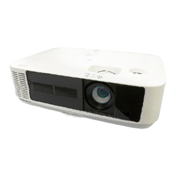
Rigel-PJ1nx Training Overview Overview External View - Front External View - Front Slide 13 Slide 13 1. Lamp Cover 2. Ventilation (outlet) 3. Lens Cover 4. Lens 5. Adjustable Tilt Foot Lever 6. Adjustable Tilt Foot 7. Controls 8. Focus Lever 9. -
Page 14: External View - Rear
Rigel-PJ1nx Training Overview Overview External View - Rear External View - Rear Slide 14 Slide 14 1. Port Cover for USB Wireless LAN Unit 2. Mono Speaker 3. Terminal Panel 4. AC Input 5. Remote Sensor 6. Built-in Security Slot 7. -
Page 15: Operation Panel
Rigel-PJ1nx Training Operation Panel Slide 15 For details: Service manual > 1. Product Information > Overview 2. The left and right arrow buttons can be used to adjust the speaker volume. - Page 16 Rigel-PJ1nx Training Menus Off Timer Wireless LAN Source Remaining Time Enabled Control Panel Eco Mode Lock Enabled High Altitude Mode High Temperature Alert Slide 16 This slide shows the Input Menu, and explains the symbols that appear on the menu screen. For details of all functions, see the user’s manual.
- Page 17 Rigel-PJ1nx Training Menus Slide 17 This slide shows the other four menu tabs. Note that in the Adjust, Setup, and Info tabs, there is more than one page. For example, in the Adjust tab, there are three pages: Picture, Image Options, and Audio.
-
Page 18: Connection Ports
Rigel-PJ1nx Training Overview Connection Ports Interface Slide 18 1. USB Port (Type A) 2. LAN Port (RJ-45) 3. USB (PC) Port (Type B) 4. HDMI In Connector (Type A) 5. Computer 2 Audio In Mini Jack (Stereo Mini) 6. Computer 2 In / Component Input Connector (Mini D-Sub 15 Pin) 7. - Page 19 Rigel-PJ1nx Training Locations of Main Units - 1 Main Board Engine Unit Integrators OPT BASE After removing the top cover, you see the main board. This board must be removed to access the optical adjustments. After you remove the main board, you can see these major subassemblies: OPT BASE: Contains the LCD panels, cross prism, and projection lens housing Engine unit: Contains the relay lens, field lens, polarizers and the dichroic mirrors Integrators: These are the PBS units...
- Page 20 Rigel-PJ1nx Training Locations of Main Units - 2 Lamp Power Supply Projection Lens Slide 20 Please ignore the callouts [A] and red circles in the diagram.
- Page 21 Rigel-PJ1nx Training Iris Unit The Iris unit physically blocks the light path from the projector to the screen when the projector is on but nothing is being projected. At these times during a presentation, a blank white screen is often not desirable. So, there are three ways to get around this.
-
Page 22: Service Training
Rigel-PJ1nx Training Y015/Y016 Service Training Basic Points about Service Slide 22 This section explains the basic points about servicing the machine. - Page 23 Rigel-PJ1nx Training Antistatic Clothing To protect the components from damage, wear anti-static clothing when you disassemble the machine. Slide 23 No additional notes...
-
Page 24: Special Tools
Rigel-PJ1nx Training Special Tools There are a lot of special tools for working on this machine. See the list in the service manual for details. Slide 24 Service manual: 3. Replacement and Adjustment > Special Tools... - Page 25 Rigel-PJ1nx Training Software Required for Service Overview Software for the following purposes must be installed on the computer that you will use to service this machine: For writing data to the machine » Used after replacing the Main PWB For writing the EDID to the machine »...
- Page 26 Rigel-PJ1nx Training Software Required for Service For Writing Data to the Machine There is a software package to install on your PC, and a data file (one for each model). For writing the model-specific product data » Writing software: PJUpgrader2.exe »...
- Page 27 Rigel-PJ1nx Training Software Required for Service For Writing the EDID to the Machine There is one software package to install on your PC, and two data files for each model. EDID rewriting software » EDIDWrite.exe EDID data (HDMI) » modelname_EDID_HDMI_Vxxx.bin EDID data (D-Sub) »...
- Page 28 Rigel-PJ1nx Training Software Required for Service For Writing Serial No. and Model No. to the Machine Software: snwriter000002.zip Decompress and install Slide 28 This is the same software as used for servicing the Sirius-PJ1.
- Page 29 Rigel-PJ1nx Training Software Required for Service For Service Adjustments Service adjustment software must be installed: Ser_X6180NSeries.exe The PC must use Windows XP or 2000, and either of serial ports COM1 - COM9 must be D-SUB9-pin To install the software, copy the following files to any folder on the PC.
-
Page 30: Entering Service Mode
Rigel-PJ1nx Training Entering Service Mode There are two service modes. Expert Mode Service Mode You need to use the remote controller to access these modes. Expert mode: » Help > Up > Left > Help. » Then press the Menu button to display the menu. -
Page 31: Error Log
Rigel-PJ1nx Training Page 1 – Error Log Expert Mode Service Mode The Error Log is seen on Page 1 of Expert Mode or Page 1 of Service Mode. The service mode screen has more detail. Slide 31 No additional notes... - Page 32 Rigel-PJ1nx Training Page 2 – Various Data Expert Mode Service Mode The service mode screen has lamp voltage data. Slide 32 No additional notes...
-
Page 33: Factory Reset
Rigel-PJ1nx Training Factory Reset The items that are reset in service mode are the same as in user mode. See the service manual for a list of items that are reset. Slide 33 Service manual: Troubleshooting > Service Mode Note that in the Sirius-PJ1, the items that are reset are different between user mode and service mode. - Page 34 Rigel-PJ1nx Training Troubleshooting - LED Display The status of the LEDs indicate the machine’s condition. See the table ‘LED Display’ in the Troubleshooting section of the service manual. LEDs Slide 34 No additional notes...
- Page 35 Rigel-PJ1nx Training Cleaning Filters, lens and cabinet are cleaned by the user. Do not use alcohol or glass lens cleaner for the lens. A plastic lens is used. Other optics parts can be cleaned with pure alcohol. Slide 35 No additional notes...
-
Page 36: Replacing The Lamp
Rigel-PJ1nx Training Replacing the Lamp To replace the lamp, unplug the power cord and then wait for the lamp to become cool. This may take as long as 60 minutes. Slide 36 No additional notes... -
Page 37: Service Training
Rigel-PJ1nx Training Y015/Y016 Service Training Replacement of Components Slide 37 This section explains the most important points about replacing components. -
Page 38: Removing The Top Cover
Rigel-PJ1nx Training Removing the Top Cover Be careful when lifting off this cover. The PCB Shutter and main board are attached to the top cover and connected through a cable. Remove them carefully, making sure the top cover faces down towards the lens side. When removing the top cover, make sure to keep the lens cover open. - Page 39 Rigel-PJ1nx Training After Removing the Top Cover Main Board Engine Unit Integrators OPT BASE After removing the top cover, you see the main board. This board must be removed to access the adjustments. After you remove the main board, you can see these major subassemblies: OPT BASE: Contains the LCD panels, cross prism, and projection lens housing Engine unit: Contains the relay lens, field lens, polarizers and the dichroic mirrors Integrators: These are the PBS units...
- Page 40 Rigel-PJ1nx Training Other Important Units Lamp Power Supply Projection Lens Slide 40 Please ignore the callout [A] in the diagram.
- Page 41 Rigel-PJ1nx Training Starting the Projector when the Top Cover and Lamp Cover have been Removed - 1 The lamp cover switch is mounted on the main board. The projector cannot be started if the lamp cover and top cover have been removed. Prepare a strip of cardboard as shown on the left.
- Page 42 Rigel-PJ1nx Training Starting the Projector when the Top Cover and Lamp Cover have been Removed - 2 Insert the folded cardboard in the right side of the lamp cover switch [C]. Insert it along the lamp cover switch. Connect the Main PWB Assy and the PWB Shutter Assy with the 3P extension board and...
- Page 43 Rigel-PJ1nx Training Installing the Lamp Cover and Top Cover Install the top cover first, then the lamp cover. If you do it the other way, the lamp cover switch may be damaged by the embossed part of the lamp cover assembly. Slide 43 No additional notes...
-
Page 44: Pcb Network
Rigel-PJ1nx Training PCB Network When handling this board [A], keep it away from conductive materials such as metals. Slide 44 No additional notes... - Page 45 Rigel-PJ1nx Training Lamp Fan When installing the lamp fan, pay careful attention to where the bracket is inserted. Slide 45 No additional notes...
- Page 46 Rigel-PJ1nx Training Replacing the Main PWB Before replacing the main board, copy all data from the current Main PWB to your PC Service adjustment software is required: Ser_X6180NSeries.exe – see Software Required for Service earlier in the presentation). If this process failed, then some steps of the data writing process have to be skipped, as shown below.
- Page 47 Rigel-PJ1nx Training Replacing the OPT BASE The service parts are all produced so that the configuration of the LCD panels is LRL. There is no need to worry about whether the LCD panels are L-type or R-type when installing new parts.
- Page 48 Rigel-PJ1nx Training Polarizers The polarizers (Polarizer- G, Polarizer-R, Polarizer- B) can be removed from their frames. Make sure that the edge with the [B] faces upwards. After you replace one or more polarizers, do the polarization plate adjustment. Slide 48 Replacement Procedure: Service manual >...
- Page 49 Rigel-PJ1nx Training Polarizers When you replace a polarizing plate inside its holder, make sure that the claws are holding the plate as shown on the left. Slide 49 No additional notes...
-
Page 50: Service Training
Rigel-PJ1nx Training Y015/Y016 Service Training Adjustments after Replacing Components Slide 50 This section explains the most important points about adjustments that are needed after replacing components. - Page 51 Rigel-PJ1nx Training When are Adjustments Needed? Adjustments are needed after replacing these parts: Main board OPT BASE Polarizers After replacing the main board, data must be written to the new board, and adjustments must be made at the operation panel. After replacing the OPT BASE, some of this data must also be input (flicker adjustment, usage time) However, after replacing the OPT BASE or polarizers, you...
- Page 52 Rigel-PJ1nx Training Optical Axis and Polarizer Adjustments Accessing the Adjustment Points Adjustment Points The main board must be removed (as shown on the left). Then, it must be connected again to the internal components of the projector (as shown on the right), because we have to switch the power on to make the adjustments.
- Page 53 Rigel-PJ1nx Training Optical Axis and Polarizer Adjustments Accessing the Adjustment Points Polarizer Adjustments Optical Axis Adjustments Here is a close up of the adjustment points. The front of the projector is at the top of the diagram. The three optical axis adjustments are called RL2, CLG, and CLB Slide 53 RL2, CLG, and CLB refer to various components in the machine, which you will...
- Page 54 Rigel-PJ1nx Training Optical Axis and Polarizer Adjustments When to do These Adjustments? Optical axis adjustment: After replacing the OPT BASE Polarizer adjustments: After replacing the polarizers or the OPT Base Slide 54 No additional notes...
-
Page 55: Optical Axis Adjustment
Rigel-PJ1nx Training Optical Axis Adjustment - 1 It is best to do this procedure in a dark room. Turn on the projector. In the SETUP menu, display a white test pattern. This can be done from the Expert mode or Service mode menus. - Page 56 Rigel-PJ1nx Training Optical Axis Adjustment - 2 Check for shadows at the edges of the display. During the adjustment, we must try to get rid of the shadows as much as possible. If shadows appear at the top and bottom edges [A], adjustment is needed in the vertical direction.
- Page 57 Rigel-PJ1nx Training Optical Axis Adjustment - 3 After you have looked at the shadows on the screen, then look at this flow chart to see which adjustments must be made. The red squares on the flow chart show the four possible decisions, as described on the previous slide.
- Page 58 Rigel-PJ1nx Training Optical Axis Adjustment - 4 These spacers are used for the adjustments. They are available as service parts. They are not shipped with the projector. The same spacers can be used for all three adjustments. Slide 58 The numbers to the right of the diagram refer to the spacer thickness.
- Page 59 Rigel-PJ1nx Training Optical Axis Adjustment - 5 Optical Axis Adjustments Just to remind you where the three adjustment points are. Slide 59 No additional notes...
- Page 60 Rigel-PJ1nx Training Optical Axis Adjustment - 6 First, adjust in the vertical direction with spacers. Adjustment Loosen the screw and insert spacers until the amount of shadow is as small as possible. Use as few spacers as possible to make up the required thickness.
-
Page 61: Polarizer Adjustment
Rigel-PJ1nx Training Polarizer Adjustment Front of Projector Blue Green Turn on the projector. In the SETUP menu, set BACKGROUND to BLACK. Loosen the screw for one of the polarizers. Move the plate from side to side. Stop at the location where the screen is darkest, and tighten the screw. - Page 62 Rigel-PJ1nx Training Writing Data to New Boards Before Removing the Main Board: Overview Copy all data from the current Main PWB to your If this process failed, then some steps of the data writing process have to be skipped. This will be explained on the next slide. Slide 62 We will look at this procedure in more detail later.
- Page 63 Rigel-PJ1nx Training Writing Data to New Boards After Removing the Main Board: Overview Data writing: After replacing the Main PWB Data for each model EDID Data Serial number and Model number Data Read/Write: After replacing the Main PWB (skip this part if the data could not be copied from the old Main Board) Flicker Data...
- Page 64 Rigel-PJ1nx Training Writing Data to New Boards Connect the Projector to a Computer Serial Cable AC Input Power Cable Before you remove the old main board: Connect the projector (PC CONTROL port) to your PC with a serial cable (D-SUB9pin - D-SUB9pin, Cross (reverse) cable) Slide 64 No additional notes...
- Page 65 Rigel-PJ1nx Training Writing Data to New Boards Copying Data from the Old Main Board to a PC - 1 Do this procedure before you remove the main board. Start the service adjustment software Ser_X6180NSeries.exe Click ‘SetUp’. For Port, select the port that you are using. Then set the Baud rate as shown above.
- Page 66 Rigel-PJ1nx Training Writing Data to New Boards Copying Data from the Old Main Board to a PC - 2 Click ‘Adjust Start’. Click ‘Data’. Select ‘All’, then click ‘Read’. You will be asked to input a file name. The data from the old main board will be stored here.
- Page 67 Rigel-PJ1nx Training Writing Data to New Boards Data Writing After Replacing the Main Board - 1 After we install a new main board, we use the following software: For writing the model-specific product data » Writing software: PJUpgrader2.exe » File names: modelname_mdata.bin This software does not write the data you just copied from the old board.
- Page 68 Rigel-PJ1nx Training Writing Data to New Boards Data Writing After Replacing the Main Board - 2 Connect the computer to the projector (USB cable). USB Cable AC Input Power Cable Hold down the Back and Menu buttons on the projector, and turn on the projector’s power. Release the Back and Menu buttons when the Power lamp blinks green.
- Page 69 Rigel-PJ1nx Training Writing Data to New Boards Data Writing After Replacing the Main Board - 3 First, select the COM port, and set the Baud rate. The setting must be the same as the Baud rate setting on the projector (Menu button –...
- Page 70 Rigel-PJ1nx Training Writing Data to New Boards Data Writing After Replacing the Main Board - 4 Now we must write EDID data to the main board. EDID rewriting software » EDIDWrite.exe EDID data (HDMI) » modelname_EDID_HDMI_Vxxx.bin EDID data (D-Sub) » modelname_EDID_DSUB_Vxxx.bin We copy the digital data first, then the analog data.
- Page 71 Rigel-PJ1nx Training Writing Data to New Boards Data Writing After Replacing the Main Board - 5 Select ‘Flash’. Set up the Port and baud rate. The Baud rate must be the same as the Baud rate setting on the projector (Menu button –...
- Page 72 Rigel-PJ1nx Training Writing Data to New Boards Data Writing After Replacing the Main Board - 6 For the analog data, connect the computer to the projector with an RGB cable. VGA RGB Cable AC Input Power Cable Slide 72 Extended display identification data (EDID) is data which describes the capabilities of a video output device, such as a projector, to a source of video data, such as a computer.
- Page 73 Rigel-PJ1nx Training Writing Data to New Boards Data Writing After Replacing the Main Board - 7 Select ‘Flash’. Set the Port to DDCAUTO. No baud rate is selected. Click ‘Choose’ and browse for the file. Select the analog file: modelname_EDID_DSUB_Vxxx.bin Put the projector in service mode.
- Page 74 Rigel-PJ1nx Training Writing Data to New Boards Data Writing After Replacing the Main Board - 8 Now we must write the serial number and model number to the new main board. Start snwriter000002.zip Slide 74 No additional notes...
- Page 75 Rigel-PJ1nx Training Writing Data to New Boards Data Writing After Replacing the Main Board - 9 Input serial number and model name here Set the Baud rate as shown above. The Baud rate must be the same as the Baud rate setting on the projector (Menu button –...
- Page 76 Rigel-PJ1nx Training Writing Data to New Boards Data Writing After Replacing the Main Board - 10 Start the service adjustment software Ser_X6180NSeries.exe Click ‘SetUp’. For Port, select the port that you are using. Then set the Baud rate as shown above. The Baud rate must be the same as the Baud rate setting on the projector (Menu button –...
- Page 77 Rigel-PJ1nx Training Writing Data to New Boards Data Writing After Replacing the Main Board - 11 Click ‘Adjust Start’. Then click ‘Data’. If data reading from the old main board failed, then skip the rest of this slide. Go to the next slide. Select ‘All’, then click ‘Write’.
- Page 78 Rigel-PJ1nx Training Writing Data to New Boards Data Writing After Replacing the Main Board - 12 The procedure on the previous slide copies the following data (which is from the old board) to the new board: Flicker Data VT Data Uniformity Data Color Correction Data Wall Color Data...
- Page 79 Rigel-PJ1nx Training Writing Data to New Boards Data Writing After Replacing the Main Board – 13 To input flicker data and usage time data, we use the service adjustment software Ser_X6180NSeries.exe Set up the software as shown on ‘Data Writing After Replacing the Main Board, slide 10’.
- Page 80 Rigel-PJ1nx Training Writing Data to New Boards Data Writing After Replacing the Main Board – 14 Chiral: Do not adjust Select ‘Floor’. Display the Red raster signal by clicking ‘Test R’ in the Test Pattern box. Adjust the R-scroll bar so that the flicker in the middle of the window becomes as small as possible.
- Page 81 Rigel-PJ1nx Training Writing Data to New Boards Data Writing After Replacing the Main Board – 15 Now we write the usage time data. Click ‘Usage Time’. Slide 81 No additional notes...
- Page 82 Rigel-PJ1nx Training Writing Data to New Boards Data Writing After Replacing the Main Board – 16 Select the type of usage time that you wish to input (lamp, filter, panel, or projector). Adjust the time with the scroll bar. Click ‘Set’. When “Please Power Off (Standby state).”...
-
Page 83: Service Training
Rigel-PJ1nx Training Y015/Y016 Service Training Updating Firmware Slide 83 This section explains the basic points about updating the firmware. Service Manual Procedure: 4. System Maintenance > Firmware Update... -
Page 84: Updating The System Firmware
Rigel-PJ1nx Training Updating the System Firmware Check the IP address of the projector. In the following example, the IP address is xxx.xxx.xxx.xxx Open a browser, and input the following: http://xxx.xxx.xxx.xxx/upload.html Click [Browse]. Select the file to be overwritten, then click [Update], then [OK]. ‘File written successfully’... - Page 85 Rigel-PJ1nx Training Y015/Y016 Service Training Technical Reference Slide 85 This section contains technical information on how the electronics in this model work. In many of the following slides, the main part of the slide shows a circuit diagram, and the notes page contains the description.
- Page 86 Rigel-PJ1nx Training I/O Terminals - 1 Video input terminals Computer1/2 input (Mini D-SUB 15-pin, 2 system) HDMI input (HDMI terminal,1 system) Video input (RCA Phono terminal,1 system) S-Video input (S terminal,1 system) USB-B (USB-B terminal 1 system) *USB Display Video output terminal Monitor output (Mini D-SUB 15-pin,1 system for Computer1 only) Slide 86...
- Page 87 Rigel-PJ1nx Training I/O Terminals - 2 Audio input terminals For COMPUTER1 input (Stereo mini jack, 1 system) For COMPUTER2 input (Stereo mini jack, 1 system) When USB Display, Viewer, or Network is selected, audio output is available when the input signal is applied to the Computer2 terminal.
- Page 88 Rigel-PJ1nx Training I/O Terminals - 3 Audio output terminal Computer/Video/S-Video input common (Mini jack, 1 system) Control terminal PC control terminal (Min D-SUB 9-Pin, 1 system) Wired LAN terminal RJ-45 terminal (RJ45, 1 system) Wireless LAN Terminal USB-A terminal (USB-A terminal, 1 system exclusively for the wireless LAN unit) USB Viewer Terminal USB-A terminal (USB-A terminal, 1 system)
-
Page 89: Input Signals
Rigel-PJ1nx Training Input Signals - 1 Signal level RGB signal: 0.7Vp-p /75 Ω Component signal: 1.0Vp-p/75 Ω ((Signal Y), 0.7Vp-p/75 Ω ((Cb/Cr,Signal Pb/Pr) VIDEO signal: 1.0Vp-p/75 Ω S-VIDEO signal: 1.0Vp-p/75 Ω ((Signal Y), 0.286Vp-p/75 Ω ((Signal C burst level) Sync signal: TTL level (Positive/Negative polarity)/1k Ω... - Page 90 Rigel-PJ1nx Training Input Signals - 2 HDMI digital signals Maximum resolution: WSXGA+( 1680x1050) @60Hz Component signals 525i, 625i, 480p, 576p (DVD output signal) 720p, 1080i, 1080p (HDTV signal) Video input color system NTSC3.58 NTSC4.43 PAL-M PAL-N PAL-60 SECAM Slide 90 No additional notes...
- Page 91 Rigel-PJ1nx Training Video Signal Input Processor Block Slide 91 The video input signals entered in Computer1 (D-SUB 15-pin) and Computer2 (D-SUB 15-pin) are terminated at 75Ω and then respectively applied to PW- C950 (IC3001). The LPF circuit is incorporated in PW-C950 where 16-stage filter characteristics are provided.
- Page 92 Rigel-PJ1nx Training Video Signal Processor Block Slide 92 Similarly, in regard to the Video and S-Video signals, they are entered in IC3001 after the termination at 75 Ω and then converted into 10-bit digital signals in the internal A/D converter. The signals then pass through the internal video decoder circuit and the deinterlace circuit, and are output to the LCD driver block after being processed for scaling at the internal scaling circuit.
- Page 93 Rigel-PJ1nx Training Sync Signal Processor Block Slide 93 The sync signal inputs (H/V,CS) entered from Pin 15 of the Mini D-SUB are applied to IC3001. The SOG (Sync on Green) signal is branched shortly before the LPF circuit, and entered in the appropriate port of the IC3001 SOG input circuit. All processes for the changeover of each sync signal, separation, and others are carried out in IC3001.
- Page 94 Rigel-PJ1nx Training HDMI Digital Signal Processor Block Slide 94 The digital video input signals entered in the HDMI terminal are sent to Sil9127ACTU (IC1504) and then converted into digital signals of R/G/B 10-bit each. The converted signals are fed to the digital video input terminal of IC3001.
- Page 95 Rigel-PJ1nx Training Monitor Output Block Slide 95 After the termination, the video signal input entered in Computer1 (MINI D-SUB 15pin) passes through the 6dB amplifier (IC2003) so that it is maintained at 1Vp- p, and is then output. Each sync signal is output to the terminal after passing through the buffer circuit. The Monitor output can be generated while the projector standby mode is set to ‘Normal ’, however, when Power-Saving is set, and if it moves to Power-Saving, it cannot be generated.
-
Page 96: Plug And Play
Rigel-PJ1nx Training Plug & Play Slide 96 The serial control terminal of Computer1/2 (D-SUB 15-pin) pins 12 and 15 is connected to the Plug&Play IC [(IC2002) for Computer1 and (IC2001) for Computer2] so that the projector can be detected at the PC. The Plug&Play of this projector corresponds to DDC/2B and DDC/CI. - Page 97 Rigel-PJ1nx Training Audio I/O Processor Block Slide 97 The R/L signal inputs entered from the respective audio terminals are sent to the output amplifier IC (IC8003) via the audio processor IC (IC8001). Generally,the R/L signal outputs generated from the audio processor IC are multiplexed and then sent out of the internal monaural speaker (8 Ω, 10W max.).
- Page 98 Rigel-PJ1nx Training Protection Slide 98 If the status shown below has been detected, the projector makes the status LED blink and the stand-by state is recovered. For more details, refer to the appendix of the instruction manual (List of Power/Warning/Lamp Replace lamps). Detection at the time of lamp cover removal During the detection, Lamp_Off and Fan_Drive are locked at the hardware.
-
Page 99: Lamp Control
Rigel-PJ1nx Training Lamp Control Slide 99 ON/OFF control of the lamp is carried out by High/Low of the LAMP_POWER signal mapping in the GPIO of IC3502.The brightness setup and the lighting status of Normal/ECO are supervised and controlled by the serial communication function of IC3502. - Page 100 Rigel-PJ1nx Training PW-C950 Block (A/D, Video Decoder, CPU, Scaler, Closed Caption) Slide 100 The PW-C950 (IC3001) is an LSI where the video signal pickup A/D, the video decoder, the CPU, the video signal processor circuit, the OSD generator and multiplex circuits, the USB Host & Device, the Ethernet, the circuits of peripheral functions (I C bus, Slow ADC, Slow DAC, UART, GPIO), and others are assembled in one.
- Page 101 Rigel-PJ1nx Training Tight Cell2 Block (Peripheral Functions) Slide 101 The Tight Cell2 (IC3502) is a G/A circuit where various functions to be described below are accommodated for fan control, key matrix, LED control, and others. Tight Cell2 is controlled from IC3001 through the CPU bus. The functions available are as specified below.
- Page 102 Rigel-PJ1nx Training Panel Correction/Drive Processor Block Slide 102 The video signal and the timing signal for the LC panel driving inputs entered from IC3001 in the 10-bit_3ch are fed to the 12-phase decoding LC panel driver ICs (IC5501,5601,5701) in the 12-bit x2-layer x3ch via the various correction circuits of V-T correction, color unevenness correction, color correction, etc, by the panel driving/correction IC (IC5005).
- Page 103 Rigel-PJ1nx Training Automatic Trapezoidal Correction Processor Block Slide 103 The gravity acceleration sensor (IC3504) is used to detect the gradient of the projector so that the trapezoidal corrector (Keystone) can be regulated automatically. The gravity acceleration sensor generates I C output according to the gradient of the projector.
- Page 104 Rigel-PJ1nx Training Lens Cover Section Slide 104 Lens Open/Shut is detected by the STR-PWB switch (S8701). The switch output is entered in Slow ADC of IC3001 and its output level is used to identify the lens cover status. STR-PWB no connection: Screen/audio Lens cover close: Screen/audio mute Lens cover open: Normal operation...
- Page 105 Rigel-PJ1nx Training DDC/CI Processor Block Slide 105 DDC/CI is an advanced DDC/2B of the VESA standard. I C serial communication is carried out with the computer and the PW-C950 (IC3001) at pins 12 and15 of the RGB cable. It makes it possible to operate the projector from a computer through an RGB cable such as RS-232C.
- Page 106 Rigel-PJ1nx Training SUB-CPU Processor Block Slide 106 In regard to the Power-Saving mode, it is changed to PW-C950 (IC3001) in the SUB-CPU (IC4504). At that time, the Power-ON remote control decode and Power Key input signals are detected. In addition, a control signal output is fed to the motor driver IC (IC4505).
-
Page 107: Lens Cover
Rigel-PJ1nx Training Lens Cover When the lens cover is shut, screen mute (all black display) is performed. Simultaneously, audio mute is also performed. After screen mute, the lamp power becomes 25% (energy saving mode). Slide 107... - Page 108 Rigel-PJ1nx Training Lamp Modes Lamp power 100%: For Off/Auto Lamp power 80%: For ECO1 Lamp power 25%: For Mute/Lens Cover Shut *Lamp control is performed by IC3502 based on communication between UART and Ballast. Slide 108...
- Page 109 Rigel-PJ1nx Training Pre-cooling The charge in the capacitor during normal operation (when the lamp is lit) begins to discharge after the lamp is turned off, and this charge goes down slowly. Until the lamp is lit again, this voltage is read out at the Slow ADC of IC3001 so that the lapse of time can be detected after the lamp was turned off.
-
Page 110: Wireless Lan
Rigel-PJ1nx Training Wireless LAN When an appropriate wireless LAN unit is connected to the USB-A terminal (used exclusively for wireless LAN), it becomes possible to maintain wireless communication with the PC. When appropriate software is used in addition to PJ control, the PC images can be displayed at the projector.* No measures are taken for movies yet. -
Page 111: Usb Display
Rigel-PJ1nx Training USB Display When the PC and the projector are connected through a general-purpose USB cable (USB2.0), the PC images can be displayed at the projector. *The projector terminal is [USB-B terminal]. *No measures are taken for movies yet. *No measures are taken for audio signal transfer yet. -
Page 112: Usb Viewer
Rigel-PJ1nx Training USB Viewer Image files stored in the USB memory can be seen at the projector in viewer display mode. Applicable file type: JPEG Slide 112... - Page 113 Rigel-PJ1nx Training MM PWB External terminals USB-A terminal (External terminal) » USB-A (USB-A terminal System 1) *For USB memory » Standard: USB2.0 USB-A terminal (Exclusively for wireless LAN unit) » USB-A (USB-A terminal System 1) *Exclusively for wireless LAN unit »...
-
Page 114: Overall Configuration
Rigel-PJ1nx Training MM PWB Overall Configuration Slide 114 When Viewer or Network is selected, the video output from the MM PWB is generated for projection on the Main PWB side via POMM2 (70-pin connector). The interface with the Main PWB is used through POMM2 (70-pin connector). Major signals in POMM2 (70-pin connector) are related to the power supply, control signal, video signal, or audio signal. -
Page 115: Power Circuit
Rigel-PJ1nx Training MM PWB Power Circuit Slide 115 The MM PWB operates on an independent +6.2V power supply fed from Pins 1~5 and 36~40 of POMM2 (70-pin connector). This +6.2V power changes its voltage between 5.4V and 8.0V according to the operating conditions of the PJ. IC9001: 5V regulator IC (Power supply for VBUS (5V) of USB) IC9005: 3.3V regulator IC (Power supply for USB-PHY, USB-HUB, LAN-PHY) IC9002: 5V regulator IC (Pre-stage of IC9013) - Page 116 Rigel-PJ1nx Training MM PWB Slide 116 Based on the 24MHz signal of the quartz crystal oscillator (X ’Tal), IC9201 operates with the main CPU clock signal of [800MHz] in the internal PLL circuit. In combination with an external IC, it performs a variety of tasks such as USB function, wired LAN processing, wireless LAN image and video file playback processing, video signal output processing, audio signal output processing, and time display (RTC) processing.
- Page 117 Rigel-PJ1nx Training MM PWB Slide 117 The CPU (IC9201) and the USB-PHY (IC9602) are connected to the ULPI (UTMI+Low Pin Interface) that conforms to the Interface Standard between the USB controller (logical layer circuit) and the transceiver (physical layer circuit). IC9602 operates with a clock signal of the quartz crystal oscillator (X9601).
-
Page 118: Wired Lan
Rigel-PJ1nx Training MM PWB Wired LAN Slide 118 The CPU (IC9201) and the LAN-PHY (IC9603) are connected through the MII (Media Independent Interface) that is an interface to be laid between the MAC (media access control) layer and the physical layer in the LAN (Ethernet) of the 10M-or 100M-bit/sec. -
Page 119: Video Output
Rigel-PJ1nx Training MM PWB Video Output Slide 119 The CPU (IC9201) generates an output of video digital signals of RGB 8-bit each. The HD-Sync (horizontal sync signal) and the VD-Sync (vertical sync signal) are also generated. The generated video signal output is processed on the Main PWB side via the POMM2. -
Page 120: Audio Output
Rigel-PJ1nx Training MM PWB Audio Output Slide 120 The audio output of the MM PWB is available when audio output is needed at the time of motion picture playback. The 24MHz clock signal from the quartz crystal oscillator (X9601) is generated and sent to the Main PWB via the POMM2 (70-pin connector). - Page 121 Rigel-PJ1nx Training MM PWB Slide 121 The RTC (Real Time Clock) provides the functions to maintain month, day, and time. It is used in conjunction with the program timer function and validity checks for the network certificate. Even when the PJ power supply is turned off, this feature is available with the charges in the EDLC (C9669) in order to retain the time-based data.
- Page 122 Rigel-PJ1nx Training Slide 122 No additional notes...
Need help?
Do you have a question about the Rigel-PJ1nx Y105 and is the answer not in the manual?
Questions and answers