Table of Contents

Subscribe to Our Youtube Channel
Related Manuals for Jackson 10 Series


Summary of Contents for Jackson 10 Series
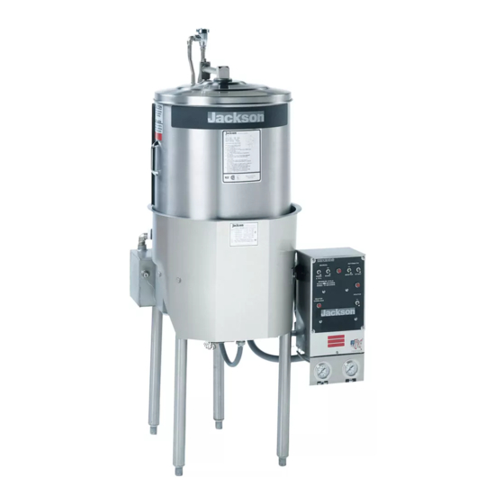
- Page 1 10 SERIES ELECTRICALLY-HEATED ROUND DISHMACHINES INSTALLATION, OPERATION, AND SERVICE MANUAL FOR JACKSON MODELS: 10AB 10APRB HIGH HOOD OPTION Model 10 Technical Manual • Revision F • P/N 07610-002-41-09 • Issued: N/A • Revised: 12-14-15...
- Page 3 The labor to repair or replace such failed part will be paid by Jackson WWS, within the continental United States, Hawaii, and Canada, during the warranty period provided a Jackson WWS authorized service agency, or those having prior authorization from the factory, performs the service.
- Page 4 REVISION HISTORY Revision Revision Made by Applicable ECNs Details Letter Date 02-24-04 Added 10 U photo installation guide and all 10U Information. Updated manufacturer inforamtion and logos. Updated manufacturer warranty. Replaced figure 5 (pg. 7) that incorrectly showed 2 O-rings 02-11-14 QOF NBD in use instead of 1.
- Page 5 10APRB = with a booster tank and a power rinse pump 10U = with a booster tank, a 4” shorter hood, and 9” shorter legs High Hood Option = hood that is 5” higher than the standard hood Jackson WWS, Inc. provides technical support for all of the dishmachines detailed in this manual.
-
Page 6: Table Of Contents
Preventative Maintenance ....................15 SERVICE PROCEDURES ..................16 Rinse Head/Wash Head Assemblies ................16 Timer for 10 Series Dishmachines ................... 19 Function of Switches, Circuit Breaker and Indicating Lights ..........21 Replacement of Switches in Control Panel ..............22 Thermostat Adjustment ..................... 23 Rinse Tank Heater System .................... - Page 7 TABLE OF CONTENTS PARTS ........................36 10A Assembly ........................36 10AB/APRB/10U Assembly ....................37 Control Box Assembly ...................... 39 Ordering Replacement Wire/Conduit Fittings ..............41 Ordering Replacement Conduit, Fittings, and Hose ............43 Tub Assembly ........................45 Bottom View Assembly ..................... 47 Wash Tank Cross View/Tub to Booster Connection ............
-
Page 8: Specifications
10A MACHINE DIMENSIONS SPECIFICATIONS LEGEND A - Water inlet 1/2” NPT. Plumbing can be directed either left or right. B - Drain connection 1 1/2” NPT 14 7/8” C - Electrical connection TO THE D - Clearance for dishes: WALL 10”... -
Page 9: 10Ab/10Aprb/10U Dimensions
10AB/10APRB/10U MACHINE DIMENSIONS SPECIFICATIONS LEGEND TOP VIEW A - Water inlet 1/2” NPT. Plumbing can be directed either left or right. B - Drain connection 1 1/2” NPT C - Electrical connection D - Clearance for dishes: 14 7/8” TO THE 10”... - Page 10 10 SERIES TABLE DIMENSIONS SPECIFICATIONS LEGEND A - 10” High backsplash, 2” turnback at 45B B - 3” High, 1 1/2” diameter rolled edge C - Scrap block D - Scrap basket with slide bars E - 20” x 20” x 5” deep pre-rinse sink F - Heavy duty pre-rinse G - 20”...
-
Page 11: Operating And Electrical Requirements
OPERATING PARAMETERS SPECIFICATIONS Model Designation: Model 10 Operating Capacity: Racks per Hour Dishes per Hour Glasses per Hour Operating Cycle (Seconds): Wash Time Rinse Time Total Cycle Time Tank Capacity (Gallons): Wash Tank Booster Tank (10AB/10APRB/10U ONLY) Pump Capacity (Gallons): Wash Pump 70 GPM Electrical Loads (as applicable):... - Page 12 Work should only be performed by qualifi ed electricians and authorized service agents. Where applicable, heating element amperage draws have been adjusted for the assumed input voltage. Jackson assumes incoming voltages will be either 208 or 230 volts. Some heating elements used in the machines are rated for other voltages, such as 240 volts.
-
Page 13: Installation/Operation Instructions
(Fig. 3 and 4) missing from the machine. This may not be obvious at fi rst. If it is discovered that an item is missing, contact Jackson immediately to have the missing item shipped to you. -
Page 14: Leveling The Dishmachine/Installing The Vacuum Breaker And Plumbing
INSTRUCTIONS INSTALLATION The dishmachine is designed to operate while be- LEVEL THE ing level. This is important to prevent any damage to DISHMACHINE the machine during operation and to ensure the best results when washing ware. The unit comes with adjustable bullet feet (Fig. -
Page 15: Aligning The Machine/Installing The Internal Vacuum Breaker/Hood Assembly
INSTRUCTIONS INSTALLATION ALIGNING THE Adjust the machine base to align hole in table with hole in support block (Fig. 10). MACHINE (Fig. 10) INSTALLING THE Insert internal vacuum breaker pipe into hood support block pin end down (Fig.11). INTERNAL VACUUM BREAKER WARNING: Internal vacuum breaker pipe must be installed... -
Page 16: Plumbing The Dishmachine/Drain Line Connection/Water Supply/Plumbing Check
INSTRUCTIONS INSTALLATION PLUMBING THE All plumbing connections must comply with all applicable local, state, and national plumbing codes. The plumber is responsible for ensuring that the incoming water line DISHMACHINE is thoroughly fl ushed prior to connecting it to any component of the dishmachine. It is necessary to remove all foreign debris from the water line that may potentially get trapped in the valves or cause an obstruction. -
Page 17: Electrical Power Connection/ Voltage Check/Final Check
Replace the lower cover and tighten down the screws. (Fig. 14) (Fig. 15) Check all fi ttings and connections before and after fi rst 10 cycles. Contact Jackson for FINAL CHECK free performance and installation check. 07610-002-41-09-F... -
Page 18: Operation Instructions
5. When placing dishes into the racks, do not allow them to lean on each other. 6. Place the glasses upside-down in the open rack. With the model 10 series, a four- compartment silverware rack is supplied. Place silver in compartment rack loosely not allowing it to mix with other silverware of the same nature. - Page 19 OPERATING INSTRUCTIONS INSTALLATION WARE Proper preparation of ware will help ensure good results and fewer re-washes. If not done properly, ware may not come out clean and the effi ciency of the dishmachine PREPARATION will be reduced. It is important to remember that a dishmachine is not a garbage disposal and that throwing unscraped dishes into the machine will defeat the purpose altogether of washing the ware.
-
Page 20: Detergent Control
This is why Jackson recommends that if you have installed the machine in an area with hard wa- ter, that you also install some type of water treatment equipment to help remove the dissolved solids from the water before it gets to the dishmachine. - Page 21 These temperatures may also be followed by temperatures that Jackson recom- mends to ensure the highest performance from you dishmachine. However, if the minimum requirements are not met, the chances are your dishes will not be clean or sanitized.
-
Page 22: Preventative Maintenance
PREVENTATIVE MAINTENANCE MAINTENANCE PREVENTATIVE Proper maintenance of your Jackson dishmachine will ensure optimum service with a minimum of down time. MAINTENANCE 1. To delime the booster tank. a. Remove the support pipe nut and lift the whole hood assembly away from the unit. -
Page 23: Service Procedures
SERVICE RINSE/WASH HEAD ASSEMBLIES PROCEDURES RINSE/WASH HEAD 1. Turn master switch to off position. ASSEMBLIES 2. Open hood and drain machine by lifting overfl ow strainer. 3. When empty, replace overfl ow strainer. 4. Remove the pin holding the rinse feed pipe and remove the feed pipe and rinse head assembly. - Page 24 SERVICE RINSE/WASH HEAD ASSEMBLIES PROCEDURES RINSE/WASH 16. Replace the lower large manifold and fi ll the raceway fully with the bearings, then remove one. HEAD ASSEMBLIES (CONTUNIED) 17. Replace the upper small manifold and fi ll raceway fully with bearings, then remove one.
- Page 25 SERVICE RINSE/WASH HEAD ASSEMBLIES PROCEDURES Rinse Feed Casting Rinse Arm Assembly Rinse Feed Casting Gasket Rinse Feed Set Screw, 10-24 x 1/2" Pipe Weldment Wash Head Cap 1/4" S/S Ball Bearings Qty. 11 Threaded Shaft Small Manifold Wash Arm 1/4" S/S Ball Bearings Qty.
-
Page 26: Timer For 10 Series Dishmachines
SERVICE TIMER FOR 10 SERIES DISHMACHINES PROCEDURES GENERAL GENERAL DESCRIPTION: The timer is a self-contained (frame mounted) timer of the repeating cycle type. It is mounted on the control panel of the control box to control DESCRIPTION the automatic functions of the machine. It consists of a clock motor which operates on 60 cycle AC, 220 VAC. - Page 27 SERVICE TIMER FOR 10 SERIES DISHMACHINES PROCEDURES SERVICE ...operations or performs a specifi c part of the cycle continuously, but works well on manual. Remember, the timer motor is controlled by the start switch and the hold INSTRUCTIONS microswitch; check this complete circuit before changing the motor. NOTE: It may be (CONTINUED) necessary to remove complete timer to replace motor;...
-
Page 28: Function Of Switches, Circuit Breaker And Indicating Lights
SERVICE SWITCHES AND CIRCUIT BREAKERS PROCEDURES FUNCTION OF SWITCHES, CIRCUIT BREAKER, AND INDICATING LIGHTS/REPLACEMENT OF SWITCHES CIRCUIT BREAKER Rated 15 amps, controls power to the control circuit only (i.e. timer, relays, solenoid valve, water level control, and motors). The circuit breaker does not cut off power in the control box at incoming terminal board and rinse heater relay contacts. -
Page 29: Replacement Of Switches In Control Panel
SERVICE SWITCHES AND CIRCUIT BREAKERS PROCEDURES REPLACEMENT OF SWITCHES IN CONTROL PANEL HEAT LIGHT This indicating light remains lit the entire time the heater switch is on. There are fi ve switches installed in the control box cover panel. These are the start, master, manual wash, rinse-fi... -
Page 30: Thermostat Adjustment
SERVICE THERMOSTAT ADJUSTMENT PROCEDURES THERMOSTAT The thermostat can be adjusted by turning screw #1 (see diagram below) on the thermostat housing cover. (Remember the preset setting in case the problems ADJUSTMENT are elsewhere in the control circuit.) A clockwise rotation is used to obtain a lower temperature setting and a counter-clockwise rotation is used to obtain a higher temperature setting. -
Page 31: Rinse Tank Heater System
SERVICE RINSE TANK HEATER SYSTEM PROCEDURES RINSE TANK The rinse tank heater system is electrically connected in the circuit and is controlled by a heater switch (mounted on the front panel) and a thermostat (mounted underneath HEATER SYSTEM near the right-front leg) which activates the coil on the heater relay, mounted in the control box. - Page 32 SERVICE RINSE TANK HEATER SYSTEM PROCEDURES RINSE TANK 2. To determine if elements are working: a. There is an insulated movable bar on the heater relay across the top of the HEATER SYSTEM two contacts. With an insulated probe, depress the bar and observe the rinse (CONTINUED) thermometer;...
-
Page 33: Wash Tank Heater System
SERVICE WASH TANK HEATER SYSTEM PROCEDURES WASH TANK The wash tank heater control system is electrically connected in the circuit to operate on 208-230 Volts. The heat circuit is controlled by a heater switch (mounted right-front HEATER SYSTEM panel), water level control (mounted top-inside control box), and thermostat (mounted underneath the right-front leg). - Page 34 SERVICE WASH TANK HEATER SYSTEM PROCEDURES WASH TANK Clamp probe on a single wire between the thermostat and wash heater element. The element should draw 3 amps. If it does not and everything above checked out okay, HEATER SYSTEM replace the element. This wash element is used to maintain wash water temperature so (CONTINUED) temperature rise will be extremely slow;...
-
Page 35: Water Level Control
SERVICE WATER LEVEL CONTROL PROCEDURES WATER LEVEL The wash heater water level control is used on this machine in conjunction with a sensor, master switch, and thermostat; all of which help control the action of the wash tank heater. CONTROL The wash heater water level control is energized when the master switch is turned on. -
Page 36: Water Level Control (Aprb)
SERVICE WATER LEVEL CONTROL FOR APRB PROCEDURES WATER LEVEL The water level control is used on this machine in conjunction with a sensing probe to detect the water level in the rinse tank and to control automatic refi lling. CONTROL (CONTINUED) When the water level decreases as the rinse pump starts to push water through the rinse tubes, the probe sends a signal to the control which deactivates the plug-in relay (located... -
Page 37: Replacing Seal And Ceramic On Wash And Rinse Pumps
SERVICE REPLACING SEAL AND CERAMIC PROCEDURES REPLACING SEAL The pump is part of the total motor-pump system and utilizes one seal and ceramic to prevent the pump from leaking around the impeller and shaft. One gasket is used to AND CERAMIC prevent leakage between the pump and mounting plate and the machine pump plate. - Page 38 SERVICE REPLACING SEAL AND CERAMIC PROCEDURES REPLACING SEAL d. Clean hole where seal was installed. e. Apply a small amount of non-hardening sealant to the backside of seal. AND CERAMIC Insert new seal with a seal driver to prevent ruffl ing the edges of the seal. ON WASH AND RINSE PUMPS CAUTION: never use a screwdriver or similar tool to alternately force edge of...
-
Page 39: Troubleshooting
COMMON PROBLEMS TROUBLESHOOTING PROBLEM POSSIBLE CAUSE REMEDY 1. No voltage to the dishmachine. 1. Replace or reset. Check to see if the customer’s fuse has blown or the circuit breaker has tripped. Nothing on the machine 2. Machine circuit breaker tripped or 2. - Page 40 COMMON PROBLEMS TROUBLESHOOTING PROBLEM POSSIBLE CAUSE REMEDY 1. Incoming water 1. Check incoming water temperature by fi rst turning off temperature under heater switch and draining the machine wash tub. required 140°F. Next, with the master switch, push the fi ll switch up Rinse water and hold for 90 seconds.
- Page 41 COMMON PROBLEMS TROUBLESHOOTING PROBLEM POSSIBLE CAUSE REMEDY 1. Thermostat needs adjustment 1. See page 23. or is faulty. 2. Check thermometer and replace if necessary. Rinse water tempera- 2. Heater relay contacts welded ture too hot (over or held shut. 200°F) and water may dribble out of the rinse 3.
- Page 42 COMMON PROBLEMS TROUBLESHOOTING PROBLEM POSSIBLE CAUSE REMEDY Rinse does not work when 1. Normally open contact on rinse 1. See page 22. manual rinse fi ll switch oper- fi ll switch faulty. ated, but does work during 2. Correct the connection. automatic cycle.
-
Page 43: Parts
10A ASSEMBLY PARTS Refer to Vacuum Breaker Assy. Page Refer to Hood Assembly Page Refer to Control Box Assy. Page FRONT VIEW ASSEMBLY REAR VIEW ASSEMBLY ITEM DESCRIPTION PART NUMBER Hood Assembly Control Box Support Bracket 05700-000-24-76 Shroud 05700-000-24-77 Bullet Feet 05340-108-01-03 Complete Control Box Assembly Vacuum Breaker Assembly... -
Page 44: 10Ab/Aprb/10U Assembly
10AB/10APRB/10U ASSEMBLY PARTS Refer to Vacuum Breaker Assy. Page Refer to Hood Assembly Page Refer to Control Box Assy. Page FRONT VIEW ASSEMBLY REAR VIEW ASSEMBLY 07610-002-41-09-F... - Page 45 10AB/10APRB/10U ASSEMBLY PARTS ITEM DESCRIPTION PART NUMBER Hood Assembly Motor and Pump Assembly 05700-002-60-91 Motor and Pump Assembly (APRB only) 05700-002-60-91 Shroud (without holes for gauges) 05700-000-24-77 Shroud (with holes for gauges) 05700-002-60-36 Control Box Support Bracket 05700-000-24-76 Bullet Feet 05340-108-01-03 Outlet Connector 05700-002-60-92...
-
Page 46: Control Box Assembly
CONTROL BOX ASSEMBLY PARTS 2, 3, 4, 5 7, 8, 9, 10, 11 18, 19, 20, 10 24, 25, 9, 10, 11 21, 22, 23 26, 27, 28 APRB only 21, 22, 23 32, 4 The complete Control Box attaches to the Control Box Support Bracket with 2 of each item: Locknut, 1/4"-20 S/S Hex... - Page 47 CONTROL BOX ASSEMBLY PARTS ITEM DESCRIPTION Mfg. No. Control Box Panel with Decal 09905-500-07-10 Timer 05945-303-19-00 Bracket, Timer Mounting 05700-000-34-28 Screw, 10-32 x 3/8” Phillips Truss Head 05305-173-12-00 Locknut, 10-32 S/S Hex with Nylon Insert 05310-273-01-00 Light, Pilot 05945-504-02-18 Block, 9 Position Terminal 05940-500-06-19 Decal, Terminal Block 09905-100-87-62...
-
Page 48: Ordering Replacement Wire/Conduit Fittings
Jackson dishmachines have several color and gauges of wire used in them and it may become necessary to replace these wires. Wire may be ordered from Jackson, but please note that it is only available in feet. Ensure that you order the correct color and gauge. - Page 49 ORDERING REPLACEMENT WIRE PARTS RED WIRE: 14 Gauge 06145-104-05-00 18 Gauge 06145-104-37-00 (CONTINUED) 18 Gauge with Black Stripes 06145-011-59-56 18 Gauge with Blue Stripes 06145-011-81-74 18 Gauge with White Stripes 06145-011-81-73 18 Gauge with Yellow Stripes 06145-011-81-75 20 Gauge 06145-104-02-97 10 Gauge 06145-002-15-91 WHITE WIRE:...
-
Page 50: Ordering Replacement Conduit, Fittings, And Hose
PARTS Jackson dishmachines come with a wide variety of conduit and fi ttings for use in routing the wires of the machine. The list below provides for most of stock of such items. When ordering, remember that Jackson does not offer pre-cut sections of conduit for your machine, instead it is sold by the foot. - Page 51 CONDUIT AND FITTINGS/HOSE AND TUBING PARTS HOSE: Hose, 3/16” ID x 5/16” OD 04720-601-40-00 Hose, 1/4” ID x .062” Wall, Excelon 04720-111-59-46 Hose, 1/4” ID x 1/2” OD, 300-350 PSI 04720-011-95-43 Hose, 3/8” ID x 5/8” OD, 300 PSI 04720-002-31-63 Hose, 3/8”...
-
Page 52: Tub Assembly
TUB ASSEMBLY PARTS 8 9 10 11 12, 13 Lundy Probe Assembly 07610-002-41-09-F... - Page 53 TUB ASSEMBLY PARTS ITEM DESCRIPTION PART NUMBER Wire Spring Ring 05315-700-03-00 Cable Assembly 03020-201-09-01 Support, Rack Weldment 05700-000-13-43 Intake Strainer 05700-000-03-02 Bulk Head Plug 04730-609-05-00 Casting, Rinse Feed 05700-000-16-47 Gasket, Rinse Feed 05330-200-02-06 Bolt, Flat Head 05305-174-14-00 Bolt, 5/16"-18 x 1" S/S Hex 05305-275-06-00 Bolt, 1/4"-20 x 1/2"...
-
Page 54: Bottom View Assembly
BOTTOM VIEW OF TUB ASSEMBLY PARTS BOTTOM VIEW ASSEMBLY (10APRB SHOWN FOR REFERENCE) Refer to Thermostat Housing 2, 3 Assembly Page 7, 8 5, 6 Wash tank section 16, 17 10, 11, 12, 13 Refer to Pump & Motor 14, 8 Assembly Page 07610-002-41-09-F... - Page 55 BOTTOM VIEW OF TUB ASSEMBLY PARTS BOTTOM VIEW ASSEMBLY (10APRB SHOWN FOR REFERENCE) ITEM DESCRIPTION Mfg. No. Shroud, (Without Holes For Gauges) 05700-000-24-77 Shroud, (With Holes For Gauges) 05700-002-60-36 Gauge, Temperature 06685-111-68-48 Decal, Wash and Rinse Temperature 09905-100-43-21 Control Box Support Bracket 05700-000-24-76 Bolt, 5/16"-18 x 1"...
-
Page 56: Wash Tank Cross View/Tub To Booster Connection
WASH TANK CONNECTION PARTS WASH TANK CROSS VIEW/TUB TO BOOSTER CONNECTION Stainless Steel Tye Wrap 5975-602-02-20 Overflow Strainer Intake Strainer 4730-017-15-05 5700-000-03-02 O-ring 5330-400-05-00 3, 4, 5 Thermal Overload 5945-301-49-00 6, 7, 8 13 14 16, 17 10 APRB REAR VIEW 10 AB/10U REAR VIEW 07610-002-41-09-F... - Page 57 WASH TANK CONNECTION PARTS ITEM DESCRIPTION PART NUMBER Gasket, Wash Heater 05330-011-61-34 Element, Wash Heater 04540-100-11-10 Washer, 1/4"-20 S/S 05311-174-01-00 Lockwasher, 1/4" Spring 05311-274-01-00 Nut, 1/4"-20 S/S Hex 05310-274-01-00 Bracket, Hood Support 05700-000-27-55 Rivet, 3/16" x 5/8" S/S CTR Flat Head 05320-107-07-00 Gasket, Hood Support Bracket 05330-200-01-06...
-
Page 58: 10Ab/Aprb Rinse Booster And Associated Parts
RINSE BOOSTER AND ASSOCIATED PARTS PARTS 10AB/10APRB/10U MODELS ONLY 10AB/10U Rinse Heater Rinse Tank Weldment 4540-100-21-10 5700-000-24-84 10APRB Rinse Tank Weldment 5700-000-24-80 Attaches with 2 Wrapper, Rinse Heater Cover Screw, 8-18 x 1/2” Tek Hex 5700-000-26-40 5305-272-01-00 Decal, Warning-Disconnect Power 9905-100-75-93 Booster Tank End View Booster Tank End View... -
Page 59: Pump And Motor Assembly
PUMP AND MOTOR ASSEMBLY PARTS ITEM DESCRIPTION PART NUMBER Complete Motor and Pump Assembly (2 for APRB units) 05700-002-60-91 Motor, 115/230 Volt, 1/2 HP, 1 PH, 60 HZ 06105-101-65-00 Flange, Motor Mounting, Epoxied and Painted 05700-002-60-97 Seal, Crane 05330-300-09-27 Seal, Ceramic 05330-300-02-27 Impeller 05700-000-19-11... -
Page 60: Thermostat Housing Assembly
THERMOSTAT HOUSING ASSEMBLY PARTS 7, 8 ITEM DESCRIPTION PART NUMBER Thermostat Box Weldment 05700-000-59-70 Front and Bottom, Thermostat Box 05700-001-21-23 Bushing, Snap in 05975-210-09-00 Thermostat, Rinse (Not used on 10A) 05930-510-02-00 Thermostat, Wash 05930-510-01-00 Overload, Thermal 05945-301-49-00 Screw, 6-32 x 1/4" S/S Round Head (2 Not used on 10A) 05305-151-02-00 Lockwasher, #6 External Tooth (2 Not used on 10A) 05311-271-02-00... -
Page 61: Incoming Plumbing Assemblies
INCOMING PLUMBING ASSEMBLIES PARTS 10AB/10APRB/10U Incoming Plumbing Assembly 5700-000-15-25 10A Incoming Plumbing Assembly 5700-002-60-98 ITEM DESCRIPTION PART NUMBER Solenoid Valve, 1/2" 208-240 Volt 04810-100-09-18 Adapter, 1/2" Fitting x Male 04730-011-59-53 Tee, 1/2" C x 1/2" C x 1/4" Female Brass 04730-411-25-01 Ball Valve, 1/4"... -
Page 62: Solenoid Valve Repair Kit/Vacuum Breaker Repair Kit
SOLENOID AND VACUUM BREAKER KITS PARTS 1/2” SOLENOID VALVE AND 1/2” NPT VACUUM BREAKER REPAIR PARTS KITS Screw Cap Screw Data Plate Coil & Housing Data Plate Valve Bonnet Spring 4810-200-04-18 Plunger Cap Retainer 4810-200-04-18 O-Ring O-Ring Diaphragm 4810-100-03-18 Retainer Plunger Diaphragm 4810-100-03-18... -
Page 63: Hood And Associated Assemblies
HOOD AND ASSOCIATED ASSEMBLIES PARTS 9, 10 07610-002-41-09-F... - Page 64 Tube, 1/2" x 15 1/2" Copper, 4SH/10U 05700-002-61-08 Tube, 1/2" x 24 1/2" Copper, 5HH 05700-000-62-92 Coupling, 1/2" with Groove 05700-011-88-42 Ring, Retaining 05340-112-01-11 Decal, Jackson 09905-004-03-02 Decal, Caution 09905-101-12-28 Decal, Operating Instructions 09905-101-12-39 Decal, Clean Strainers and Probe 09905-100-28-42...
- Page 65 HOOD AND ASSOCIATED ASSEMBLIES PARTS ITEM DESCRIPTION PART NUMBER Hood Assembly, Complete Standard 05700-000-25-91 Hood Assembly, Complete 4”SH/10U 05700-002-17-69 Hood Assembly, Complete 5”HH 05700-002-61-09 07610-002-41-09-F...
-
Page 66: Vacuum Breaker/Connector Assemblies 10A Series
VACUUM BREAKER/CONNECTOR ASSEMBLIES PARTS MODEL 10A ASSEMBLIES Complete Vacuum Breaker Assembly, Standard 5700-002-61-18 Complete Vacuum Breaker Assembly, 4SH 5700-002-44-79 Complete Vacuum Breaker Assembly, 5HH 5700-002-61-66 Plated Outlet Assembly, Standard Plated Inlet Assembly, Standard 5700-002-61-21 5700-002-61-20 Plated Outlet Assembly, 4SH Plated Inlet Assembly, 4SH 5700-002-61-69 5700-002-61-70 Plated Outlet Assembly, 5HH... -
Page 67: Vacuum Breaker/Connector Assemblies 10Ab/10Aprb/10U
VACUUM BREAKER/CONNECTOR ASSEMBLIES PARTS 10AB/10APRB/10U ALL UNITS ASSEMBLIES Outlet Connector Assembly Vacuum Breaker 5700-002-60-92 4820-300-07-00 Union, Female Half 5700-002-61-85 10U Vacuum Breaker, Plated 5700-002-62-61 Plated Inlet Assembly, Standard 5700-002-61-10 Elbow, 90 CU to MSPS Plated Inlet Assembly, 4SH 4730-406-32-01 Before Machine Serial No. 45973 Copper Tube, 1/2”... -
Page 68: Parts List For 10 Dishmachines
PARTS LIST FOR MODEL 10 DISHWASHERS PARTS PART NO. DESCRIPTION SERIAL NO. QTY. 6401-000-54-00 Booster Tank for machine (stripped) AB AF 28,000 6401-000-58-00 Booster Tank for machine (stripped) APRB AF 28,000 5925-105-10-01 Circuit Breaker, 15 amp (specify number from part) Specify 0016300 Control Box, Complete Wired A... - Page 69 PARTS LIST FOR MODEL 10 DISHWASHERS PARTS PART NO. DESCRIPTION SERIAL NO. 6680-200-02-68 Probe, Large Hi-Level (APRB only) 6680-200-05-68 Rubber Cover (for Hi-level probe) (APRB only) 6401-008-50-00 Pump Assembly, Complete w/Motor, 1/2 HP, AF 24,451 6105-101-65-00 Pump Motor, 115-230V, 1/2 HP, 3450RPM, jet AF 24,451 5330-300-09-27 Pump Seal (for pump parts 850-863-920-925)
- Page 70 PARTS LIST FOR MODEL 10 DISHWASHERS PARTS PART NO. DESCRIPTION SERIAL NO. QTY. 5930-301-22-18 Switch, Heat (DPST) (all) slip disconnect AF 24,451 5930-301-23-18 Switch, Start (SPDT) (all) slip disconnect AF 24,451 6401-016-55-00 Terminal Board, 3-Pole, complete (three-phase) 5940-500-06-19 Terminal Board, 9-Pole, complete slip terminal AF 24,451 6685-200-01-10 Thermometer, Wash or Rinse, Standard...
-
Page 71: Schematics
10A, 10AB/10U, 10APRB SCHEMATICS 10A 208/220V 1 PHASE 09905-002-57-63 A TERMINAL WASH WASH BOARD #1 MOTOR HEATER CIRCUIT BREAKER CUSTOMER SERVICE 15 AMP RATING ½ HP 630 WATTS 5.3 AMPS 10AB/10U 208/220V 1 PHASE 09905-105-33-59 B RINSE HEATERS TERMINAL WASH WASH BOARD #1 MOTOR... -
Page 72: Wiring Diagram (208-230 Volt, 60Hz, Single Phase)
10A WIRING DIAGRAM PARTS 10A WIRING DIAGRAM (208-230 VOLT, 60HZ, SINGLE PHASE) 07610-002-41-09-F... -
Page 73: 10Ab Wiring Diagram (208-230 Volt, 60Hz, Single Phase)
10AB WIRING DIAGRAM SCHEMATICS 10AB WIRING DIAGRAM (208-230 VOLT, 60HZ, SINGLE PHASE) 07610-002-41-09-F... -
Page 74: 10Ab Wiring Diagram (208-230 Volt, 60Hz, Three Phase)
10AB WIRING DIAGRAM PARTS 10AB WIRING DIAGRAM (208-230 VOLT, 60HZ, THREE PHASE) 07610-002-41-09-F... -
Page 75: 10Aprb Wiring Diagram (208-230 Volt, 60Hz, Single Phase)
10APRB WIRING DIAGRAM SCHEMATICS 10APRB WIRING DIAGRAM (208-230 VOLT, 60HZ, SINGLE PHASE) 07610-002-41-09-F... -
Page 76: 10Aprb Wiring Diagram (208-230 Volt, 60Hz, Three Phase)
10APRB WIRING DIAGRAM PARTS 10APRB WIRING DIAGRAM (208-230 VOLT, 60HZ, THREE PHASE) 07610-002-41-09-F... - Page 78 Jackson WWS, Inc. • 6209 N. US Hwy 25E • Gray, KY 40734 USA 1.888.800.5672 • www.jacksonwws.com Model 10 Technical Manual • Revision F • P/N 07610-002-41-09 • Issued: N/A • Revised: 12-14-15...
Need help?
Do you have a question about the 10 Series and is the answer not in the manual?
Questions and answers