Table of Contents
Advertisement
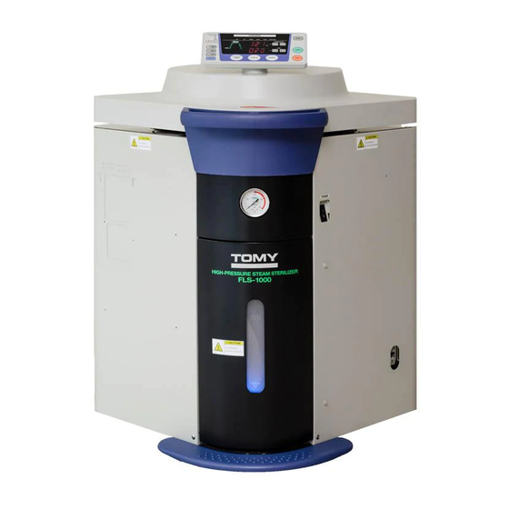
OPERATOR'S MANUAL
A U TO C L AV E
● Please read this Operator's Manual thoroughly and understand the
contents before operating FLS-1000.
● This equipment is used for the handling of microorganisms, such as
bacteria and viruses, which can exert adverse health effects on human
beings or other living things, therefore, must be used by personnel
with enough knowledge and experience.
● Be sure to keep this Operator's Manual handy for future reference.
FLS-1000
FOR RESEARCH USE
Advertisement
Chapters
Table of Contents

Related Manuals for Tomy FLS-1000


Summary of Contents for Tomy FLS-1000
- Page 1 A U TO C L AV E FLS-1000 ● Please read this Operator’s Manual thoroughly and understand the contents before operating FLS-1000. ● This equipment is used for the handling of microorganisms, such as bacteria and viruses, which can exert adverse health effects on human beings or other living things, therefore, must be used by personnel with enough knowledge and experience.
-
Page 2: Table Of Contents
2-2.Parts Identifications・・・・・・・・・・・・・・ 6-6.Annual Inspection Reminder Function・・・・・・・・・・・・・・・・・・・・・・・・ P.44 3. INSTALLATION・・・・・・・・・・・・・・・・・・・・・・ P.18 6-7.Setting the Time Unit for Display・・・ P.45 3-1.Moving and Installing the FLS-1000・・・ P.18 6-8.Selecting the Exhaust Setting for the 3-2.Connecting to the Power Source Liquid Sterilization Course・・・・・・・・ P.46 and Grounding・・・・・・・・・・・・・・・・・・ P.21 6-9.Setting the Temperature to Release... -
Page 3: 1.Precaution For Use
FLS-1000 or other property. Be sure to read this Operator ’s Manual thoroughly before use, and follow its instructions and procedures for the proper use of FLS-1000. -
Page 4: 1-2.Warnings And Cautions
Failure to do so may cause FLS-1000 to fall Failure to do so may cause accidental fire, over, thereby resulting in personal injury or short circuit or malfunction. - Page 5 Connect the FLS-1000 to a power outlet When the pressure gauge is not working of the voltage specified as correct for properly, stop operation. FLS-1000. Do not connect it to a shared Otherwise, abnormality inside the outlet. chamber, if any, cannot be found, thereby Failure to do so may cause accidental fire, causing serious accident.
- Page 6 If any abnormality is as a basket provided with the FLS-1000 to found, please contact your dealer or our prevent the vent hole and its surrounding local representative.
- Page 7 When returning FLS-1000 or any parts of When disposing or transferring FLS-1000 FLS-1000 for replacement or repair, FLS- or its parts, FLS-1000 or the parts must 1000 or the parts must be appropriately be appropriately decontaminated before decontaminated before shipping it in any...
-
Page 8: 2. General Information
2-1. Operating Principles When the FLS-1000 starts operation, sterilizing water inside the chamber is heated up by the element heater at the bottom of the chamber to generate steam. The steam generated from heated water drives air out from the chamber and warms up the interior of the chamber. - Page 9 MEMO ー 8 ー...
-
Page 10: 2-2.Parts Identifications
2-2. Parts Identifications < FLS-1000 Main Unit > ⑦ ⑧ ① ② ⑨ ③ ⑪ ④ ⑤ ⑩ ⑥ ⑮、 ⑯ ⑫ ⑬ ⑰ ⑭ ー 9 ー... -
Page 11: Lid
It displays the pressure ⑨ It is used to turn on or off the attached, and three swivel reading inside the chamber. power to FLS-1000. casters in other three corners. <Pressure display range> 0 〜 0.4 MPa Leakage breaker Level adjustment bolt ⑩... - Page 12 Top plate Lid hook catch Safety valve hole ㉔ ㉘ ⑳ Lid hook Chamber lid Chamber ㉕ ㉙ ㉑ It locks the chamber lid in the Chamber lid gasket Hinge closed position. ㉖ ㉚ It maintains air-tightness of Hinge shaft Lid hook boot the pressure vessel.
-
Page 13: Exhaust Tank
Magnetic catch Exhaust tank Exhaust tank cap ㉟ ㊳ ㉝ Air and steam exhausted from Exhaust tank water level the chamber is collected into Drain cock ㊴ ㉞ sensor this exhaust tank. Drain hose for chamber It detects the water level of the ㊵... -
Page 14: Chamber
< Chamber Interior > Access port ① The temperature sensor for articles to be sterilized or the external temperature sensor can be installed into the chamber through this port. Temperature sensor ② It detects the temperature inside the chamber. Heating element (heater) ③... - Page 15 < Piping Diagram > Safety valve Air release valve Trap bottle Pressure gauge Pressure sensor Exhaust tank Ball valve ー 14 ー...
-
Page 16: Function
The lid cannot be for the sterilization course while opened while it is on. the FLS-1000 is in standby mode, falling process is indicated by the number of turned on bars. and the chamber temperature... -
Page 17: Liquid Sterilization Course
EXT. SENSOR key Press this key to select the operation. liquid sterilization course It is activated when the while the FLS-1000 is in STOP key external sensor for articles to standby mode. Press this key to stop an be sterilized is connected. - Page 18 It stays ⑦ process of temperature and It turns on to indicate that on when the operation is pressure rise is currently being the FLS-1000 is ready for completed normally and the performed. operation. chamber temperature drops below 60℃.
- Page 19 ● Failure to do so may cause short circuit of electric components or fire. Avoid installing the FLS-1000 in or near a sink or tap where there is a risk of it being splashed with water. ● Failure to do so may cause short circuit or electric shock.
- Page 20 ※ Four casters are mounted in the four corners of the bottom of the FLS-1000. A caster in the corner where the chamber lid handle is attached on top is a fixed one, and casters on each of the other three corners are swivel ones.
- Page 21 Choose either side and install the unit. Install the FLS-1000 providing a clearance of at least 25cm at the rear and on each side of the unit. Maintain sufficient space for access in front and above the unit.
- Page 22 FLS-1000. ※ For the power requirements of the FLS-1000 please refer to “11-1. Specifications of the FLS-1000”. Plug the FLS-1000 directly into a power outlet of the specified voltage. Do not connect it to a shared outlet.
- Page 23 The FLS-1000 operates by generating steam under pressure and temperature. Therefore, its sterilization process can be greatly affected by the atmospheric pressure at the location where the FLS-1000 is installed. In order to ensure proper operation of the FLS-1000 please reset the altitude level if it is moved to another location.
- Page 24 4. OPERATIONAL FLOW 1. Turning on the power switch P.24 2. Checking the pressure gauge P.27 3. Checking the water level of the exhaust tank P.28 4. Checking the sterilizing water in the chamber P.30 5. Placing articles to be sterilized P.31 6.
-
Page 25: Turning On The Power Switch
5. OPERATION 5-1. Turning On/Off the Power Switch WARNING Do not touch the power switch with a wet hand. ● Failure to do so may cause electric shock. < To turn on the power > Check that the power supply is correctly ①... - Page 26 5-2. Opening and Closing the Chamber Lid WARNING Never attempt to open the lid until the chamber pressure returns to 0MPa. ● If the lid is opened while pressure remains in the chamber, articles to be sterilized or steam may gush out, thereby resulting in death or serious injury. Be extremely careful of steam coming out of the chamber when opening the chamber lid.
- Page 27 < To open the chamber lid > Check that the pressure gauge reads “0MPa”. ① Check that the power switch is at “ON” position. ② Check that the IN PROGRESS indicator on the ③ control panel turns off or the COMPLETED indicator in the work monitor display flashes.
-
Page 28: Checking The Pressure Gauge
5-3. Checking the Pressure Gauge WARNING When the pressure gauge is not working properly, stop operation. ● Otherwise, abnormality inside the chamber, if any, cannot be found, thereby causing serious accident. If pressure gauge malfunction is suspected, please contact your dealer or our local representative. <... -
Page 29: Checking The Water Level Of The Exhaust Tank
● Water in the chamber or the exhaust tank may be very hot after the operation, causing burns. The FLS-1000 discharges hot steam during the operation. To prevent accidents, such as burn injuries, the steam exhausted from the chamber is captured in the trap bottle after passing through the water in the exhaust tank. - Page 30 < To pour water into the exhaust tank > Check that the water inside the exhaust tank is cooled down. ① Open the drain access cover. ② Remove the exhaust tank cap. ③ Pour water in the exhaust tank through the feed-water inlet until the water level exceeds the ④...
-
Page 31: Checking The Sterilizing Water In The Chamber
5-5. Checking the Sterilizing Water in Chamber The FLS-1000 generates steam by heating up the sterilizing water in the chamber, which has a heating element in its bottom. Check the quality and level of the sterilizing water inside the chamber to perform adequate sterilization. -
Page 32: Placing Articles To Be Sterilized
Make sure that articles to be sterilized are placed in a container, such as a basket provided with the FLS-1000, to prevent the vent hole and its surrounding area from being blocked. - Page 33 < To place articles to be sterilized in the chamber > Place articles to be sterilized in the stainless steel basket provided or in an optional stainless ① steel bucket. ※ Stainless steel buckets and baskets are available as optional containers. ※...
-
Page 34: Setting Operating Parameters
5-7. Setting Operating Parameters < To set the sterilization operating parameters > Press the STERILIZE key. ① EXHAUST SPEED IN PROGRESS FAST The STERILIZE indicator lights up to indicate that CHECK WATER DRAIN COVER CHANGE WATER SLOW TEMPERATURE the sterilization course is selected, while all process STERILIZE °C indicators on the work monitor light up green. -
Page 35: Body・・・・・・・・・・・・・・・・・・・・・・・・・・・
< To perform effective sterilization > The FLS-1000 controls the temperature using the temperature detected by the temperature ○ sensor in the chamber as an index. When more reliable sterilization is required, set the appropriate conditions for sterilization using an external temperature sensor for articles to be sterilized or a sterilization index body. -
Page 36: Starting Operation
● Failure to do so may cause burns. Please keep at least 50 cm away from all four corners of the autoclave while it is in operation. Do not attempt to touch the outer panel of the FLS-1000 during or immediately after the operation. - Page 37 Check that the READY indicator is on. If it is off, ① EXHAUST SPEED IN PROGRESS follow the instructions stated in the table on the FAST CHECK WATER DRAIN COVER CHANGE WATER SLOW next page to turn the READY indicator on. TEMPERATURE STERILIZE °C...
-
Page 38: Ending Operation
Table. Operation of the indicator and buzzer in each process of the sterilization cycle Operation completed “IN PROGRESS” Lid interlocked Process status “COMPLETED” Buzzer indicator indicator indicator Preparation completed Operation started One beep ↓ ↓ ↓ Temperature rising process Yellow on One beep Temperature and pressure Red on... -
Page 39: Removing Articles To Be Sterilized
5-10. Removing Articles to be Sterilized WARNING Never attempt to open the lid until the chamber pressure returns to 0MPa. ● If the lid is opened while pressure remains in the chamber, articles to be sterilized or steam may gush out, thereby resulting in death or serious injury. Be extremely careful of steam coming out of the chamber when opening the chamber lid. -
Page 40: Draining The Sterilizing Water From The Chamber
5-11. Draining the Sterilizing Water from the Chamber WARNING Do not attempt to open the drain cock unless the pressure gauge reads 0MPa. ● If the drain cock is opened when pressure still remains in the chamber, hot water may spurt out, causing death, injury or serious accident. CAUTION Allow sterilizing water to cool down sufficiently before draining water from the chamber. - Page 41 6. USEFUL FUNCTIONS 6-1. Liquid Sterilization Function The FLS-1000 provides the liquid sterilization function which allows liquids to be sterilized. To avoid explosive boiling in the liquid sterilization course the setting of the exhaust speed and cooling fan can only be changed during the temperature and pressure falling process or temperature falling process.
- Page 42 6-2. Memory Function By using the memory function frequently used settings of operating parameters can be stored in memory and easily called up. < To store preferred operating parameters > Set and display preferred operating parameters. ① EXHAUST SPEED IN PROGRESS FAST Press and hold down the MEMORY key for ②...
- Page 43 6-4. Timer Function The timer function allows the operator to set the waiting time for the operation to start. To set the timer follow the procedures given below after setting the desired operating parameters. Press the TIMER key. ① EXHAUST SPEED IN PROGRESS FAST The timer indicator turns on and the time display...
- Page 44 6-5. Power Failure Alert Function If a power failure occurs or the autoclave is turned off at the power switch during operation, the POWER FAILURE indicator will turn on when the power is restored. If a power failure occurs before the sterilization process has completed, the time display will show the error code “A09” to indicate that the chamber is not heated when the power returns.
- Page 45 6-6. Annual Inspection Reminder Function Perform a voluntary inspection annually to ensure safe operation of the autoclave. The annual inspection reminder function will notify the operator of the timing for the annual inspection when it approaches. < When the reminder appears in the display > The reminder appears in the display as a due date ①...
- Page 46 6-7. Setting the Time Unit for Display This function allows the operator to change the time unit for display. The time unit for display for sterilization and timer can be set individually. Press the FUNCTION key while the IN PROGRESS ①...
- Page 47 6-8. Selecting the Exhaust Setting for the Liquid Sterilization Course In addition to the normal speed level setting, variable speed setting, which allows the fine adjustment of the exhaust valve opening, can be selected for the exhaust speed in the liquid sterilization course.
-
Page 48: The Lid Interlock
6-9. Setting the Temperature to Release the Lid Interlock The FLS-1000 is equipped with the lid interlock which activates and prevents the lid from opening when the lid is forced open while the chamber temperature is still high. The lid interlock release temperature can be changed depending on the operation. -
Page 49: 6-10.Sterilizing Water Change Alert
6-10. Sterilizing Water Change Alert Function When the set number of sterilization cycles is reached, the sterilizing water change indicator lights up to notify the operator of the timing for water change to prevent the chamber from getting rust by contaminated water inside. When the sterilizing water change indicator is turned on, follow the instructions below for pouring water into the chamber. -
Page 50: Function
6-11. Exhaust Tank Illumination Function Illumination of the exhaust tank displays levels of water inside and raises an alert when the water reaches full level, thereby allowing easy monitoring of the water level in the exhaust tank. The exhaust tank turns on blue when the autoclave operates a cycle with water levels in the exhaust tank between adequate levels. - Page 51 MEMO ー 50 ー...
- Page 52 7. OPTIONAL FUNCTIONS The following optional accessories and functions are available for the FLS-1000. The external temperature sensor for articles to be sterilized ■ Sterilization process is monitored using the temperature sensor for articles to be sterilized by installing it directly into the article in the chamber so that the autoclave begins the sterilization time countdown only when the temperature for articles to be sterilized has reached a set sterilization temperature and, therefore, provides adequate heating.
-
Page 53: 8. Routine Maintenance
● Otherwise, high temperature inside the chamber may cause burns. 8-1. Cleaning and Disinfecting the Main Body If the main body exterior or the chamber interior of the FLS-1000 becomes stained or dirty, clean or disinfect it according to the following procedures: <... -
Page 54: 8-2.Weekly Maintenance
Unplug and inspect the power plug regularly. ● Failure to do so may cause fire or burnout. To ensure safe operation of the FLS-1000, perform cleaning and inspection weekly according to the following procedures: < To clean each part >... - Page 55 < To inspect each part > 1. Leakage breaker Turn on the power supply switch on the main body. ① Push the gray test button provided inside the power switch with a thin rod. ② If the autoclave automatically switches off the power, the leakage breaker functions normally. If it does not switch off, contact your dealer or our local representative.
-
Page 56: 9-1.Symptoms And Solutions
9. TROUBLESHOOTING If any system malfunction in the FLS-1000 is suspected, when it is operated properly according to this Operator’s Manual, check the cause referring to the table below given in “9-1. Symptoms and Solutions” and take the corresponding remedy. If the symptom of the malfunction is not identified or the remedies described do not solve the problem, unplug the power plug of the FLS-1000 from the outlet and contact your dealer or our local representative. -
Page 57: 9-2.Error Code Table
0MPa to open the lid. And then pouring water into the chamber. Temperature inside the chamber is much Unplug the power plug of the FLS-1000 from higher than the set temperature during the the outlet and contact your dealer or our local sterilization process. - Page 58 Open the equal to or less than 30kPa. sterilization bag if it is closed. Control system malfunction Unplug the power plug of the FLS-1000 from ※ Memory abnormality the outlet and contact your dealer or our local representative.
- Page 59 ※ 1 The FLS-1000 checks the operation of the lid open/close detection system to ensure its safe operation, therefore, open and close the lid at least once before each operation or timer operation.
-
Page 60: 9-3.Contact Information
In cases where FLS-1000 or any parts of FLS-1000 has been exposed to infectious and hazardous or radioactive substances. In cases where FLS-1000 or any parts of FLS-1000 has any residue of blood or other chemicals and has been identified as hazardous. -
Page 61: 10. Disposal And Transfer
In cases where FLS-1000 or any parts of FLS-1000 has been exposed to infectious and hazardous or radioactive substances. In cases where FLS-1000 or any parts of FLS-1000 has any residue of blood or other chemicals and has been identified as hazardous. -
Page 62: 11-1.Specifications Of The Fls-1000
11. SPECIFICATIONS 11-1. Specifications of the FLS-1000 220V model 230V model 240V model Equipment category: (medical/laboratory) Laboratory equipment Model name Autoclave FLS-1000 Operating temperature Sterilize 105℃ to 123℃ range (It varies depending on altitude level.) Maximum operating pressure 0.193MPa Temperature... - Page 63 Rated current Single-phaseAC220V Single-phaseAC230V Single-phaseAC240V Power requirements 50/60Hz 15A 50/60Hz 15A 50/60Hz 15A 3.0kW 3.0kW 3.3kW Power consumption (heat output) (2,580kcal/h) (2,580kcal/h) (2,838kcal/h) Ambient temperature: from 10 to 35℃ Atmospheric pressure: from 750 to 1060hPa Relative humidity: 75% or less Altitude: not exceeding 2000m Environmental requirements...
- Page 64 (FLS-1000) Operator's Manual ID No.21023.00 Issued in August , 2018 TOMY KOGYO CO., LTD. TOMY SEIKO CO., LTD. TOMY DIGITAL BIOLOGY CO., LTD. 3-14-17 Tagara, Nerima-ku, Tokyo 179-0073, Japan e-mail : info@digital-biology.co.jp URL : http://www.digital-biology.co.jp Phone : +81-3-5971-8160 fax : +81-3-3970-6036...
Need help?
Do you have a question about the FLS-1000 and is the answer not in the manual?
Questions and answers