Table of Contents
Advertisement
Advertisement
Table of Contents

Related Manuals for Rheem Comfort Control2


Summary of Contents for Rheem Comfort Control2
- Page 1 INSTALLER GUIDE Comfort Control HD Thermostat featuring Serial Communications...
- Page 2 FAILURE TO READ AND FOLLOW ALL INSTRUCTIONS WARNING CAREFULLY BEFORE INSTALLING OR OPERATING THIS Thermostat installation CONTROL AND SYSTEM COULD CAUSE PERSONAL INJURY components of the control system shall AND/OR PROPERTY DAMAGE. conform to Class II circuits per the NEC code.
-
Page 3: Table Of Contents
Table of Contents Installation ......................Wiring Requirements ..................Quick Installation Steps ................Installing Thermostat..................Initial Power Up ..................... Check System Operation ................Thermostat Overview ..................11 Thermostat Setup ..................... 13 Set Current Time and Day ................13 Choose the System Setting ................14 Energy Saving Factory Pre-Program ............ -
Page 4: Installation
Installation This booklet contains installation instruction and information on the thermostat only. Separate installation instructions for the furnace or air handler and outdoor AC condensing unit or heat pump are provided. This thermostat is designed exclusively for the ClimateTalk communicating system. Wiring Requirements Each communicating device in the system has a four wire connection labelled (R, C, 1, 2). -
Page 5: Quick Installation Steps
Quick Installation Steps Determine location of thermostat installation. Mount thermostat base to wall. Connect wires to thermostat base. Attach thermostat to base. Turn on power to system. Allow approximately 1 minute for the system to configure. ... - Page 6 Connect wires to terminal block on base. Push excess wire into wall and plug hole with a fire resistant material (such as fiberglass insulation) to prevent drafts from affecting thermostat operation. Carefully line up the thermostat with the base and snap into place. Removable Faceplate The silver faceplate on the thermostat can be removed and replaced with the white...
-
Page 7: Initial Power Up
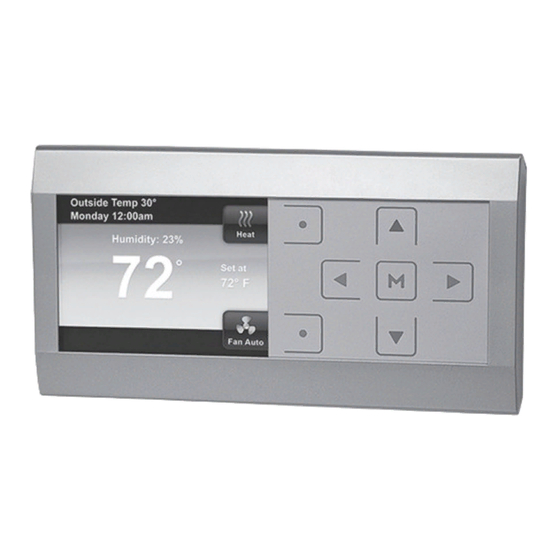
Initial Power Up Turn on AC power to the system. The thermostat will automatically identify the communicating equipment installed and configure for the equipment as required. Messages at Thermostat As equipment is found on the network, the display will show, “device” Found. The Searching icon will show until all equipment is found and configured. - Page 8 The display will change to Start-up, Hold screen showing the actual temperature, SYSTEM position (HEAT) mode, FAN setting (AUTO), HOLD AT with the setpoint temperature 62 for heat or 85 for cool and real time clock (hour, minute, AM or PM, day). Communications Systems The ClimateTalk protocol will set the identification of the individual nodes connected...
-
Page 9: Check System Operation
Check System Operation Heating System (Heat Pump only/Furnace only/Dual Fuel) 1. Press SYSTEM button until Heat is displayed. 2. Press to adjust thermostat setting 1° above room temperature. The heating system should begin to operate and the display will indicate Heat On. 3. - Page 10 4. Press to adjust thermostat setting above room temperature. The cooling system should stop operating. Fan Operation 1. Press FAN button until Fan On is displayed. The fan should begin to operate. 2. Press FAN button to change the display to Fan Auto. The fan should stop operating as long as there is no call for heat or cool.
-
Page 11: Thermostat Overview
Thermostat Overview Navigating through your thermostat menus Your thermostat features a simplified easy to understand menu structure. Press to enter the Main Menu Highlight a menu item using the buttons Enter the item by pressing Use the and the to change menu items and settings ... - Page 12 Main Menu Press to enter menu. The Main Menu lists the menus that access and set thermostat operating options and programming. Use to highlight selection 12 Installer’s Guide...
-
Page 13: Thermostat Setup
Thermostat Setup Set the Current Time and Day On the Main Menu, select and enter Clock and Display Settings. Select and Enter Time & Date. The Hour is selected. Adjust the hour with Press to select Minutes, AM/PM, Month, Day and Year and adjust. -
Page 14: Choose The System Setting
Choose the System Setting From the Home screen, press the button as shown to choose the system setting: Heat, EM, Cool, Auto, or Off. Energy Saving Factory Pre-Program Your thermostat is programmed from the factory with the energy saving settings shown below for every day of the week. -
Page 15: Advanced Installer Menu
Advanced Installer Menu This menu allows the installer to check installer-specific information or set advanced settings. It is accessible from the Home screen when the buttons are pressed at the same time for three seconds. Select the items using the buttons and press the button to enter the item to view information or change settings. - Page 16 Communicating Devices: This menu item will list each piece of system equipment connected to the ClimateTalk network. The equipment can be selected and entered to view identifying information, operating information and setup status as described in Equipment User Menus. Fault Status: This menu item lists current equipment fault conditions.
- Page 17 Once the Upload button is pressed and the upload is accomplished, the display will indicate “Successfully Installed” for 3 seconds then the display will display the menu or mode prior to entering the USB upload menu. Heat Pump Disable - Available only for heat pump systems with indoor electric heat.
- Page 18 Aux Lockout Temperature - Available for heat pump systems. This feature disables the indoor (electric or gas) heat above the selected outdoor temperature. The temperature range is from the Heat Pump Disable setting to 95°F. Dual Fuel Setpoint: If the heating system is a heat pump with gas heat and the outdoor sensor is installed, the thermostat can monitor outside temperature to determine when to begin using the gas heat system and...
- Page 19 Heat Cycle Rate - Anticipation for heat cycle can be adjusted. Default setting is Medium. If you wish to have longer heat cycles, change to Slow. For shorter heat cycles change to Fast. Cool Cycle Rate - Anticipation for cool cycle can be adjusted.
-
Page 20: Equipment User Menus
Equipment User Menus Equipment operating information and options will be found on the Advanced Installer Menu in Communicating Devices. Equipment fault status and details will be found in Fault Status. Equipment User Menus In the Communicating Devices menu, select the equipment listed that you wish to see information for. - Page 21 Status Used to display or modify equipment settings Fault History Displays information on the last six faults by code and (FAULT HIST) description that occurred throughout the system and the number of days ago that the fault occurred. 2 Week History Displays information on the number of hours of unit/ (2 WK HIST) mode operation and the number of cycles the unit has...
-
Page 22: Furnace User Menus
Furnace User Menus Status 1 Parameter Indications Comments Main Limit Closed, Open Main Limit Control Status MRLC Input Closed, Open Main Reset Limit Control Status HALC Input Closed, Open Heat Assist Limit Control Status IDM Output Off, Lo, Hi Inducer Output Status Furn Lo Pr Sw Closed, Open Furnace Low Pressure Switch Status... - Page 23 Furnace User Menus (cont.) Status 2 Parameter Indications Comments Mod Heat, Lo Heat, Indicates Operating Mode of System Hi Heat, AC1, AC2, Mode Fan Only, Off, HP1, Motor Mfgr Regblt, Emerson Blower Motor Manufacturer Motor RPM Blower Motor RPM Maximum CFM CFM XXXX Maximum CFM Blower Provides Blower CFM...
- Page 24 Furnace User Menus (cont.) Fault History (FAULT HIST) Fault Code Fault Occurred Comments Displays up to 6 Faults; Days (XX) XXXXXXXXXXXXXXX Days XX indicates how many days ago the fault occurred Clear Faults No, Yes 2 Week History (2 WK HIST) Parameter Indications Comments...
- Page 25 Furnace User Menus (cont.) Life History (LIFE HIST) Parameter Indications Comments Total number of days control has been Total Days Pwrd XXXX powered Lo HT Hrs XXXXXX Low Heat Hours of Operation Lo HT Cycles XXXXXX Low Heat Cycles Hi HT Hrs XXXXXX High Heat Hours of Operation Hi HT Cycles...
- Page 26 Furnace User Menus (cont.) Unit Info Parameter Indications Comments XXXX- Model Number Unit Model Number XXXXXXXXXXXXXXXX Unit Serial Number (Not available Serial Number XXXXXXXXXXXXXXXXXXX if control is replaced) Software Vers XXXXXX Control Software Version Setup Parameter Options Comments Heat Rise Adjust 55F, 65F Change airflow to adjust heat temperature rise Selectable Airflow Adjustments at 40% Firing Min Heat Adj %...
- Page 27 Furnace User Menus (cont.) Dipswitch* Dipswitch Indications Comments Cool Airflow XXXXCFM Airflow Dipswitch Settings AC-HP Adj -10%, 0%, 10% Heat Pump AC Airflow Settings * Dipswitch status is not required when the system is set up for 4-wire communications. It is only displayed when a conventional 24V thermostat input is active.
-
Page 28: Air Handler User Menus
Air Handler User Menus Status Parameter Indications Comments Auxiliary Heat On, Off Auxiliary Heat Status Blower CFM CFMXXXX Air Handler Blower CFM Motor Mfgr Rgblt, Emerson Blower Motor Manufacturer Motor RPM RPMXXXX Blower Motor RPM Maximum CFM CFMXXXX Maximum CFM of the Air Handler Difference Between the Supply and Return Air Temp Rise NA, XXXF, FLT... - Page 29 Air Handler User Menus (cont.) 2 Week History (2WK HIST) Parameter Indications Comments 2wk AuxHT Hrs 2 Week Auxiliary Heat Hours of Operation 2wk AuxHT Cycls XXXX 2 Week Auxiliary Heat Cycles 2wk G Hrs 2 Week Blower Hours of Operation 2wk G Cycles XXXX 2 Week Blower Cycles...
- Page 30 Air Handler User Menus (cont.) Setup Parameter Options Comments If Return Air Sensor is field installed, turn On. Return Air Sens Off, On Factory Default is Off If Supply Air Sensor is field installed, turn On. Supply Air Sens Off, On Factory Default is Off Resets the Air Handler to the Factory Default Reset All Dflts...
-
Page 31: Heat Pump User Menus
Heat Pump User Menus Status Parameter Indications Comments Compressor Off, On Compressor Status AC, AC1, AC2, HP, HP1, HP2, Mode System Mode of Operation Defrost, Time Delay, Off Comp Hi Pres SW Closed, Open Heat Pump High Pressure Switch Status Comp Lo Pres SW Closed, Open Heat Pump Low Pressure Switch Status... - Page 32 Heat Pump User Menus (cont.) 2 Week History (2 WK HIST) Parameter Indications Comments 2wk Y1 Hrs 2 Week First Stage Cooling Hours of Operation 2wk Y1 Cycles XXXX 2 Week First Stage Cooling Cycles 2wk Y2 Hrs 2 Week Second Stage Cooling Hours of Operation 2wk Y2 Cycles XXXX 2 Week Second Stage Cooling Cycles...
- Page 33 Heat Pump User Menus (cont.) Life History (LIFE HIST) Parameter Indications Comments Total Days Pwrd XXXX Total Number of Days Control has been Powered Y1 Hrs XXXXXX First Stage Cooling Hours of Operation Y1 Cycles XXXXXX First Stage Cooling Cycles Y2 Hrs XXXXXX Second Stage Cooling Hours of Operation...
- Page 34 Heat Pump User Menus (cont.) Cool Setup Parameter Options Comments Selectable Airflow Profiles AC Profile A, B, C, D (see Heat Pump Installer Guide) Cool Air Adj % -10, 0, 10 Selectable Cooling Airflow Adjustments On Demand On, Off Select Blower Operation on based on humidity Dehum Resets the Heat Pump to the Factory Default Reset All Dflts...
-
Page 35: Air Conditioner User Menus
Air Conditioner User Menus Status* Parameter Options Comments Compressor Off, On Compressor Status AC, AC1, AC2, Mode System Mode of Operation Time Delay, Off Comp Hi Pres SW Closed, Open AC High Pressure Switch Status Comp Lo Pres SW Closed, Open AC Low Pressure Switch Status Outdoor Ambient Temperature Display Outdr Temp Sens... - Page 36 Air Conditioner User Menus (cont.) 2 Week History (2 WK HIST) Parameter Indications Comments 2wk Y1 Hrs 2 Week First Stage Cooling Hours of Operation 2wk Y1 Cycles XXXX 2 Week First Stage Cooling Cycles 2wk Y2 Hrs 2 Week Second Stage Cooling Hours Operation 2wk Y2 Cycles XXXX 2 Week Second Stage Cooling Cycles...
- Page 37 Air Conditioner User Menus (cont.) Unit Info Parameter Indications Comments Model Number XXXX-XXXXXXXXXXXXXXXX Unit Model Number Unit Serial Number (not Serial Number XXXXXXXXXXXXXXXXXXX available if control is replaced) Software Vers XXXXXX Control Software Version Cool Setup Parameter Options Comments Selectable Airflow Profiles AC Profile A, B, C, D (See AC Installer Guide)
-
Page 38: System Fault Codes
SYSTEM FAULT CODES Display Code Diagnostic Description Display Code Diagnostic Description Long Run Time High Line Voltage System Pressure Trip 29 (L29) High Pressure Switch Trip Short Cycling Fuse Open 4 (L4) Locked Rotor MRLC Open 5 (L5) Open Circuit Low pressure switch closed, inducer off 6 (L6) - Page 39 SYSTEM FAULT CODES Display Code Diagnostic Description Display Code Diagnostic Description No inducer control communication Freeze protection No gas valve feedback Air Freeze protection Servo control fault Compressor Protector Fault No Gas Valve Feedback No Shared Data Low Airflow Insufficient Indoor CFM Return air sensor out of range Memory Card Invalid Supply air sensor out of range...
- Page 40 Part No. 37-7309A 1205...
Need help?
Do you have a question about the Comfort Control2 and is the answer not in the manual?
Questions and answers