Table of Contents
Advertisement
Quick Links
INSTALLATION
INSTRUCTION
MODELS K*BU060A, K*BC090A, & K*BC120A
GENERAL
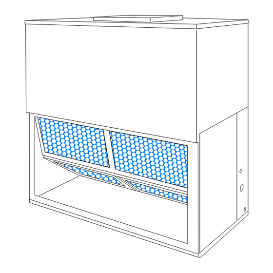
These completely assembled 5, 7-1/2 and 10 ton blower
units include a well insulated cabinet, a DX cooling coil with
copper tubes and aluminum fins, an expansion valve, a
distributor, throwaway filters, a centrifugal blower, a blower
motor contactor and a small holding charge of refrigerant-22.
Blower motors and adjustable drives are factory-installed on
all units.
The units are shipped in the vertical position ready for field
installation. For horizontal installation, reverse the solid
bottom panel and the return air duct flange on the front of
the unit.
INSPECTION
As soon as a unit is received, it should be inspected for
possible damage during transit. If damage is evident, the
Installer should pay particular attention to the words: NOTE , CAUTION and WARNING. Notes are intended to clarify or make the installa-
tion easier. Cautions are given to prevent equipment damage. Warnings are given to alert installer that personal injury and / or equipment
damage may result if installation procedure is not handled properly.
AIR COOLED
SPLIT-SYSTEM AIR CONDITIONERS
Supersedes: 550.23-N2W (589)
extent of the damage should be noted on the carrier's freight
bill. A separate request for inspection by carrier's agent
should be made in writing.
RENEWAL PARTS
Refer to Parts Manual for complete listing of replacement
parts on this equipment for complete listing of replacement
parts. The forms referenced in this instruction may be
ordered from:
Publications Distribution Center
Unitary Products Group
P.O. Box 1592, York, PA. 17405
This instruction covers the installation and operation of
evaporator blower units. For information on the operation of
the matching condensing unit, refer to Forms 550.46-N1W,
550.46-N2W and 550.23-N1W.
550.23-N2Z (399)
035-16673
Advertisement
Table of Contents

Related Manuals for Luxaire K*BU060A Series


Summary of Contents for Luxaire K*BU060A Series
- Page 1 AIR COOLED INSTALLATION SPLIT-SYSTEM AIR CONDITIONERS INSTRUCTION Supersedes: 550.23-N2W (589) 550.23-N2Z (399) 035-16673 MODELS K*BU060A, K*BC090A, & K*BC120A GENERAL extent of the damage should be noted on the carrier’s freight bill. A separate request for inspection by carrier’s agent These completely assembled 5, 7-1/2 and 10 ton blower should be made in writing.
-
Page 2: Table Of Contents
550.23-N2Z TABLE OF CONTENT TABLES General ................1 Description Page Renewal Parts..............1 Unit Application Data ........Inspection................1 Physical Data..........Blower Motor Pulley Adjustment ....INSTALLATION Blower Performance ........Limitations ................3 Accessory Static Resistance...... Location................3 Blower Motor and Drive Data ..... Clearances ................ -
Page 3: Installation
550.23-N2Z INSTALLATION LIMITATIONS The units should be located as close to the condensing units as practical and positioned to minimize bends in the This unit must be installed in accordance with all national refrigerant piping. and local safety codes. If no local codes apply, installation must conform to the appropriate national code. -
Page 4: Rigging And Handling
550.23-N2Z RIGGING AND HANDLING Ducts should be sized no smaller than the duct flanges on the unit or the electric heater (if used). Refer to the unit Be careful when moving the unit. Do not remove any dimension details (Figure 12 and 13) and the heater detail packaging until the unit is near its final location. - Page 5 550.23-N2Z TABLE 2 - PHYSICAL DAT UNIT MODEL DESCRIPTION Rows Deep x Rows Wide 3 x 24 3 x 27 3 x 32 Finned Length - inches EVAPORATOR COIL Face Area - square feet 10.2 Tube OD - inches Fins per inch CENTRIFUGAL BLOWER Diameter x Width - inches 10 x 10...
-
Page 6: Drain Connection
550.23-N2Z MODEL 5 TON 7-1/2 & 10 TON 16-7/8 19-1/4 20-1/8 22-1/4 FIG. 5 - SUPPLY AIR PLENUM ACCESSORY FIG. 4 - ELECTRIC HEATER ACCESSORY FIG. 7 - RETURN AIR GRILLE ACCESSORY FIG. 6 - BASE ACCESSORY NOTE: These units can only be piped from one side of the unit. CAUTION: Always puncture sealing caps and discs with a small drill bit before unbrazing to prevent the pres- EXPANSION VALVE BULB... -
Page 7: Supply Air Blower Adjustment
550.23-N2Z DRAIN STEEL STUB CONNECTION PLASTIC 3" EVAPORATOR COIL 2" HOSE CLAMPS DRAIN PLUG FIG. 8 - RECOMMENDED DRAIN PIPING NOTE: Refer to Figure 12 or 13 for minimum clearance re- quirements. SUPPLY AIR BLOWER ADJUSTMENT The RPM of the supply air blower will depend on the required CFM, the unit accessories and the static resistances of both the supply and the return air duct system. -
Page 8: Blower Performance
550.23-N2Z FIG. 11 - PRESSURE DROP ACROSS A DRY EVAPORATOR COIL VS. SUPPLY AIR CFM After the supply air blower motor is operating, adjust the 2. Insert at least 8" of 1/4 inch tubing into each of these holes resistances in both the supply and the return duct systems for sufficient penetration into the airflow on both sides of the to balance the air distribution throughout the conditioned evaporator coil. -
Page 9: Blower Motor And Drive Data
550.23-N2Z TABLE 5 - STATIC RESISTANCES FOR UNIT ACCESSORIES (IWG) Unit Model Accessory 1600 1800 2000 2200 2400 10 KW 0.01 0.01 0.01 0.02 0.02 Electric Heaters 16 KW 0.01 0.02 0.02 0.03 0.04 26 KW 0.02 0.03 0.04 0.05 0.08 Supply Air Plenum 0.03... -
Page 10: Electric Heater Accessory
550.23-N2Z 7/8" HOLE W/BUSHING 36-1/8 IN REAR PANEL (For Low Voltage 8-1/2 13-1/4 Control Panel) 7/8" KNOCKOUT 1-23/32 KNOCKOUT IN REAR PANEL (Removed only when (For Power Wiring) Electric Heat Accessory 3-7/8 is used) 4-1/2 11-1/2 2-1/4 22-3/4 11-5/8 2-5/16 BLOWER MOTOR AND DRIVE ACCESS PANEL... - Page 11 550.23-N2Z 1-3/8" KNOCKOUT FOR POWER WIRING (Back Panel) Do not remove this knockout when the unit is equipped with an Electric Heat Accessory. Refer to detail of the Heater Accessory for power wiring access opening 52-1/4 7/8" HOLE W/BUSHING FOR CONTROL 15-3/8 18-7/8 WIRING...
-
Page 12: Power And Control Wiring
550.23-N2Z 1-PHASE LINE VOLTAGE TERMINALS ON SUPPLY AIR POWER SUPPLY BLOWER MOTOR CONTACTOR POWER WIRING DISCONNECT SWITCH AND FUSING TO BE SUPPLIED BY FIELD GROUND SCREW 1-PHASE KBU060 24-VOLT CONTROL 24-VOLT TERMINALS ON WIRING TERMINALS ON CONTROL 1ST STAGE WIRING COMPRESSOR COOLING CONTACTOR M... -
Page 13: Maintenance
550.23-N2Z TABLE 7 - ELECTRICAL DATA - Cooling Only Unit Model Motor Blower HP Power Supply Full Load Amps Maximum Fuse Size , Amps Maximum Wire Length , Feet 208/230-1-60 208-3-60 1-1/2 230-3-60 460-3-60 208-3-60 230-3-60 460-3-60 Dual element, time delay fuses. Based on three, 60°C, 14 AWG, insulated copper conductors in steel conduit and a 3% voltage drop. - Page 14 550.23-N2Z Unitary Products Group...
- Page 15 550.23-N2Z Unitary Products Group...
- Page 16 Supersedes 550.23-N2W(589) Subject to change without notice. Printed in U.S.A. Copyright © by Unitary Products Group 1999. All rights reserved. 550.23-N2Z (399) Code: SBL, F, C, A Norman Unitary 5005 Oklahoma Products York 73069 Group Drive...
Need help?
Do you have a question about the K*BU060A Series and is the answer not in the manual?
Questions and answers