Table of Contents
Advertisement
Advertisement
Table of Contents

Related Manuals for Empress Effects ECHOSYSTEM


Summary of Contents for Empress Effects ECHOSYSTEM
- Page 1 user manual version 1.05...
- Page 2 INTRODUCTION We're stoked you've chosen to make the Empress Echosystem part of your sound! We hope you use it to create new and amazing sonic textures. In time, those sounds may make you a superstar. At which point, we hope you remember us and invite us back stage so we can impress our wives and children.
- Page 3 Warm Analog Delay Delay and Reverb Echoplex...
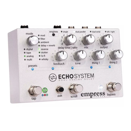
- Page 4 Controls a engines: press to cycle through mode selector: selects which the 4 di erent routing modes. mode is active. Each mode can have many submodes which are hold tap and press engines to indicated by di erent color LEDs. send current tempo from the active delay to the other delay when using dual engines, press...
- Page 5 at a Glance delay time | ratio: controls the delay time. in tap mode, it controls the ratio of the delay mix: sets the ratio of wet signal time relative to the tempo (delay) to dry signal (una ected). that is tapped. Counterclockwise is 100% dry, clockwise is 100% wet, with 50/50 being somewhere around 2 o’clock.
- Page 6 MODE REFERENCE CHART Mode Description Thing 1 Thing 2 Digital Pristine Clean and pristine Modulation Modulation Depth Rate Short Stuff 1980 Divides tap time by 4 for Mod Depth Bandwidth really short sounds. Perfect for slap-back Ping Pong Classic ping pong delay Modulation Modulation Depth...
- Page 7 Multi Digital Multi Multitaps Intensities Intensity Depth (one per dot) and pan width. Tone Taps The tone of each tap is Tone Variations Intensity Depth different (one per dot) and Pan Width. Preset Pattern It takes a single tap and Delay Time Volume and Pan Mode...
- Page 8 Delay + Reverb Hall Delay and hall reverb Mix of Delay to Reverb Decay Reverb Plate Delay and plate reverb Mix of Delay to Reverb Decay Reverb Reverse Reverse Delay Chops the input signal up High Frequency Compression and plays it backwards Roll-Off Amount Reverse Dual...
- Page 9 Whisky Knobs' Seesaw Two pitched delay lines. Sets pitch Sets pitch when When input signal gets when playing playing gets above a threshold it quiet louder switches from one line to the other. Christopher Two pitched delays that Sets pitch of Sets pitch of Glitchens have fully variable pitch...
- Page 10 SETTING DELAY TIME To change the delay time source, hold the shift button and press the tap stompswitch. DELAY TIME SOURCES Local Tap (Tap LED shines Red): When the user taps in a tap time, it gets scaled by the ratio knob, and is saved with the preset.
- Page 11 USING DUAL DELAY ENGINES The Echosystem has two engines which can each run any mode. You can route these engines in parallel, serial, or split left/right. When using dual engines, two mode LEDs light up. The bright one is the mode whose controls are active. Press down on the mode knob to toggle which mode is active.
- Page 12 When cycling through the presets, after your final preset, all the preset LEDs will flash very quickly. This represents the manual preset. If you recall this preset, the Echosystem will get its settings from the current knob positions. In the manual preset, no preset LEDs are lit.
- Page 13 Saving a Preset To save the current settings to a preset, press the scroll stompswitch until you reach the preset location where you want to write. While the lights are flashing, hold down the shift button and press the scroll stompswitch. Your preset is now saved.
- Page 14 BANK PRESET SYSTEM Preset Organization In Advanced Configuration you'll select the number of banks you wish to use. The preset LEDs display which bank is selected by changing color. The middle and right stompswitches each represent a preset. So there are two presets per bank. Recalling a Preset and Bypassing the Pedal To recall a preset, press on the middle or right stompswitch.
- Page 15 BANK PRESET SYSTEM - WITH EXTERNAL TAP If you'd like three presets per bank, you can use an external tap switch. By setting the pedal's Advanced Configuration to bank presets and the control port setting to either normally-open tap or normally-closed tap you will get 3 presets available per bank. (Changing the delay time source is done by holding the shift button and pressing the external tap in this configuration.)
-
Page 16: Expression Pedal
CONTROL PORT The control port jack allows the Echosystem to be controlled by a multitude of devices. The pedal ships configured to accept an expression pedal. Please see the Advanced Configuration section on how to configure the control port for the device you plan to use. - Page 17 CONTROL VOLTAGE (CV) With CV control, the Echosystem responds to CV signals from 0 to 5 volts. Otherwise, the CV configuration works exactly like the expression pedal configuration. EXTERNAL TAP SWITCH The Echosystem can be used with either a normally-open or a normally-closed external switch.
- Page 18 4 channels above the Echosystem's current MIDI channel. For example, if the Echosystem is set to MIDI channel 5 and preset 3 is loaded, the Echosystem will send out MIDI program change 3 on MIDI channels 6, 7, 8 & 9.
- Page 19 MIDI CONTROL CHANGE MESSAGES REFERENCE Echosystem Note: Parameter Engine Engine Modes The modes and sub-modes are numbered starting from 0 (Digital = 0, Tape = 1, etc.) To translate the modes and sub- mode to a single number you apply the following equation:...
- Page 20 Middle Stomp – Sending a value of 64 Scroll simulates a quick tap. Sending a value of 127 simulates the Right Stomp – switch being pressed and held Bypass until a value of zero is sent, Shift Button simulating releasing the switch.
- Page 21 USING HARDWARE INSERT External effects can be inserted into the delay line using hardware insert. You’ll need to enable this mode in advanced configuration. Then, connect as below: In this configuration the unit operates in mono. Left/right routing won't function as expected. If using dual delays, the hardware insert goes on engine 0 (the first delay when in series).
- Page 22 ADVANCED CONFIGURATION The advanced configuration customizes how your pedal operates. The options are listed in the table that follows. Entering Advanced Configuration While holding down the tap and bypass stompswitches, press the shift button. All the preset LEDs will blink yellow twice to confirm you're in.
- Page 23 ADVANCED CONFIGURATION REFERENCE Option Set mode LED to: preset LEDs indicate: Bypass operation 1. True hardwire bypass*** Digital 2. Buffered bypass.* 3. Buffered bypass with isolation transformer on right output. (Note: when transformer is engaged the pedal assumes stereo output operation) Control port 1.
- Page 24 Cabinet Simulator 1. Cab sim is off.* Reverse puts a cabinet simulation 2. Bright 4x12 cab. algorithm on the output, 3. Dark vintage cab useful if you don't have 4. Balanced modern cab an amp. Signal Configuration 1. stereo in/stereo out.* Stutter 2.
-
Page 25: Firmware Updates
This pedal has firmware that can be updated with an SD card. Performing A Firmware Update 1) download the firmware file off the website www.empresseffects.com/echosystem-firmware 2) copy the file to the root directory of the SD card (a high-capacity SD card that's been formatted FAT32) 3) insert the SD card then power on the pedal. -
Page 26: Factory Reset
WARNING! This will overwrite your current presets and advanced config settings and replace them with the factory presets and default advanced config settings! To restore the Echosystem to its factory settings, do the following: while in the advanced configuration (see Entering Advanced Configuration): press and release the stompswitches in this order: Tap, Bypass, Tap, Bypass. - Page 27 THANK YOU Paul Uhl, Gabriel Tanaka, Patrick Zdunich, Knobs, Matt Cyr, Steve Foley. LEGAL STUFF FCC Compliance Note: This equipment has been tested and found to comply with the limits for a Class B digital device, pursuant to part 15 of the FCC Rules. These limits are designed to provide reasonable protection against harmful interference in a residential installation.
-
Page 28: Specifications
SPECIFICATIONS Input Impedance: 1MΩ Output Impedance: 100Ω Output Impedance (transformer): 600Ω Frequency Response (-3dB, dry): 10Hz – 50kHz Frequency Response (-3dB, wet): 10Hz – 23.4kHz Total Harmonic Distortion (dry): 0.09% Total Harmonic Distortion (wet): 0.22% Dynamic Range (dry): 106.9 dBA Dynamic Range (wet): 105.5 dBA Input Headroom (dry):...
Need help?
Do you have a question about the ECHOSYSTEM and is the answer not in the manual?
Questions and answers