
Related Manuals for Trikdis CG17


Summary of Contents for Trikdis CG17
- Page 1 Cellular security control panel CG17 Installation manual March, 2019 www.trikdis.com UAB Trikdis Draugystės str. 17, LT-51229 Kaunas, Lithuania +370 37 408 040 info@trikdis.lt...
-
Page 2: Table Of Contents
“W ” ................................. 24 IRELESS WINDOW 3.6.1 Pairing a wireless device RF-SH transceiver to the CG17 ..................24 3.6.2 Pairing wireless sensors (FW2) ..........................24 3.6.3 Pairing a wireless keyfob (FW2) ........................... 25 3.6.4 Pairing a wireless siren (FW2) ..........................25 3.6.5... -
Page 3: Safety Precautions
Cellular security control panel CG17 Safety precautions The electronic intruder alarm system should only be installed and maintained by qualified personnel. Please read this manual carefully prior to installation in order to avoid mistakes that can lead to malfunction or even damage to the equipment. -
Page 4: Description
Features Sends events to monitoring station receiver: Sends events to TRIKDIS software or hardware receivers that work with any monitoring software. Can send event messages to SIA DC-09 receivers. Connection supervision by polling to IP receiver every 30 seconds (or by user defined period). -
Page 5: Device Types
Configuration either using an USB cable or remotely using TrikdisConfig software. Two types of access levels (accounts), for the installer and for the administrator. Device types This manual applies to these CG17 models: CG17_12, CG17 control panel with 2G modem. ... -
Page 6: Purpose Of Terminals
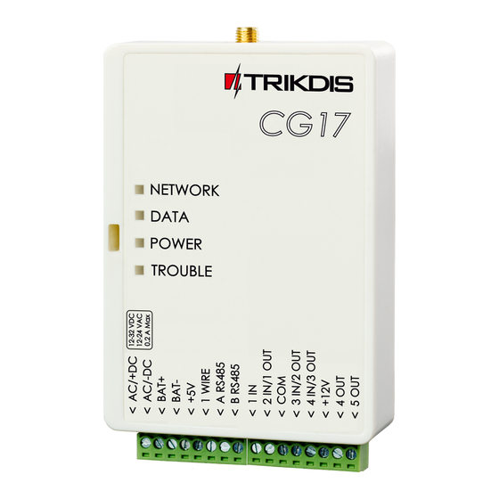
1. SMA type connector for GSM antenna 2. LED indicator lights 3. Slot for opening the top lid 4. Terminal blocks for external connections 5. USB Mini-B port for programming the CG17 6. Nano SIM card slot Terminal Description AC / +DC... -
Page 7: Led Indication Of Operation
Schematics and installation process Mounting 1. Before beginning, make sure that the GSM signal level is sufficient in the place where the CG17 will be mounted. 2. Remove the top lid, remove the plug parts of both terminal blocks. 3. Remove the PCB. - Page 8 If you do not want to enter the PIN code in TrikdisConfig, insert the SIM card into a mobile phone and disable PIN code requests. 8. If you want to be able configure the CG17 remotely, insert a SIM card with disabled PIN code requests. Send an SMS message: CONNECT 123456 PROTEGUS=ON,APN=INTERNET 9.
-
Page 9: Schematics For Connecting I Oseries Extension Modules
Schematics for connecting inputs The CG17 has four inputs IN for connecting various alarm system sensors. Possible ways to connect a sensor: NO – normally open contact; NC- normally closed contact; EOL – normally closed circuit with a 10kΩ end of line resistor. Possible connection... -
Page 10: Schematics For Connecting A Temperature Sensor
EOL zone (or NC, no resistor). b) using an EOL zone (or NO, no resistor). *SM1 – a compatibility module made by Trikdis that allows to remotely restart a two-wire smoke detector after a triggered alarm. Schematics for connecting a temperature sensor ... -
Page 11: Schematics For Connecting Contact Key Readers
Cellular security control panel CG17 Schematics for connecting contact key readers The TM17 reader should be connected to the CG17 using an RS485 data bus. The wire length of an RS485 data bus can be up to 300 m. The iButton key reader should be connected to the CG17 using the “1 Wire” port. The wire length can be up to 30 m: Note: Linking keys to the CG17 is described in chapter 33.4.1 „Registration of contact (iButton) keys”. -
Page 12: Schematics For Connecting Of The Fuel Level Sensor Strela Rs485
Cellular security control panel CG17 Schematics for connecting of the fuel level sensor Strela RS485 Configuring and preparing the fuel level sensor to work with the CG17 It is mandatory to calibrate the fuel level sensor “STRELA S485” (http://strela-fls.com/products/fuel_level_sensors_strela.html) using the manufacturer’s calibration software DUTConfig (http://strela-fls.com/programs.html) and specify the fuel tank’s capacity –... - Page 13 Cellular security control panel CG17 6. Click the “Edit” button and calibrate the sensor in full and empty tank modes. 7. Calibrating under real conditions: a) Fuel tank is full and the sensor is inside the fuel tank – click the button Full tank;...
-
Page 14: Schematics For Connecting A Battery
13. Disconnect the fuel level sensor and connect it to the CG17. Schematics for connecting a battery A 12 V battery can be connected to the CG17. If AC power is lost, an event message “AC fault” will be sent and the CG17 will automatically switch to the 12 V battery. -
Page 15: Description Of Trikdisconfig Status Bar
4. Launch the configuration program TrikdisConfig. The program will automatically recognize the connected device and will automatically open the CG17 configuration window. 5. Click the Read [F4] button to see the current parameters of the CG17. If prompted, enter the administrator or installer code in the pop-up window. -
Page 16: System Options" Window
0 to 999 minutes. Call – after an event, the CG17 will call user(s) as many times as is specified. If the call is declined or answered, the CG17 will stop calling. Call time is 20 seconds. - Page 17 Cellular security control panel CG17 Siren squak on arm/disarm – the siren will make a short sound once when the alarm is armed and twice when it is disarmed. Entry time – time for entering through the “Delay” zone. Time is anywhere from 0 to 999 seconds.
-
Page 18: Reporting To Cms" Window
GPRS mode is set both for the primary and backup channels. SMS messages will be sent to the receiving center: 1) as soon as the CG17 is turned on for the first time; and 2) after loss of TCP/IP or UDP/IP connectivity on the primary and backup channels. -
Page 19: Users & Reporting" Window
If PGM and REC boxes are not ticked, but both A and D are selected, when the user calls the CG17, their call will be declined, and the alarm will change its operational status to the opposite state, i.e., the alarm will be armed or disarmed. -
Page 20: Registration Of Contact (Ibutton) Keys
Cellular security control panel CG17 Settings group “iButtons” Note: More than one key can be assigned to a user! All newly registered keys will be assigned to the User ID9 (No name). Names can be assigned only to eight users. Permissions for User ID 9 can be set using the settings group User ID9 permissions. -
Page 21: Modules" Window
Name – you can give a name to the module. Firmware version – the firmware version will be shown once the CG17 detects the connected module. Settings group “Internal modules” Module type – choose the GPS module that is being used. -
Page 22: Linking A Fuel Level Sensor Strela Rs485
Module – select the module FLS fuel sensor. Click Write [F5]. Wait until the data is saved. Remove the USB cable from the CG17. Wait for about 1 minute. Connect the USB cable to the CG17. Click Read [F4]. The program will read and show the settings currently saved on the CG17. The Serial No. and Firmware version of the fuel level sensor Strela S485 will appear in the program window Modules. - Page 23 Every time the fuel level sensor is turned on, it measures the current fuel level and compares it to the fuel level that was saved to memory before the sensor was turned off. If the current fuel level is lower, the CG17 sends messages about fuel loss to the security company and/or to users.
-
Page 24: Wireless" Window
The CG17 can operate with Crow brand wireless Shepherd series sensors, sirens, remote controls using an RF-SH module. 3.6.1 Pairing a wireless device RF-SH transceiver to the CG17 1. Connect the RF-SH transceiver to the CG17 according to the schematic at 2.8 “Schematic for connecting a wireless sensor RF-SH transceiver”. -
Page 25: Pairing A Wireless Keyfob (Fw2)
Write [F5]. The wireless sensor is now deleted from the CG17’s memory. 3.6.3 Pairing a wireless keyfob (FW2) 1. Make sure that the wireless RF-SH transceiver is linked to the CG17 (see chapter 33.6.1 above). 2. Turn on the power. 3. Remove the lid from the RF-SH transceiver. -
Page 26: Pairing Wireless Sensors (Sh)
6. The flash will stop binking. The wireless siren’s default settings have been restored. 3.6.5 Pairing wireless sensors (SH) 1. Make sure that the RF-SH transceiver is paired to the CG17 (see chapter 33.6.1 above). 2. Turn on the power. -
Page 27: Pairing A Wireless Keypad (Sh)
Cellular security control panel CG17 3.6.6 Pairing a wireless keypad (SH) 1. Make sure that the wireless RF-SH transceiver is linked to the CG17 (see chapter 33.6.1 above). 2. Turn on the power. 3. Remove the lid from the RF-SH transceiver. - Page 28 Cellular security control panel CG17 When the alarm is armed, a violation of the “Delay” zone starts the entry time counter, during which the alarm must be disarmed. If the alarm is still not disarmed when the time is up, outputs OUT “Siren” and “Flash” are turned on and alarm reports are sent.
-
Page 29: Pgm" Window
“Outputs” tab PGM No– the PGM’s number on the list. PGM output – assign the CG17’s or external device’s outputs OUT to a PGM. Areas – assign an output OUT to an area. Output definition – choose operational mode for the output OUT. - Page 30 Cellular security control panel CG17 Pulse OFF – initial state of output OUT - „On“. After a command the OUT state will become “Off” during the Pulse time, and later it will automatically return to the initial “On” state. Pulse ON – initial state of output OUT - „Off“. After a command the OUT state will become “On” during the Pulse time, and later it will automatically return to the initial “Off”...
- Page 31 Cellular security control panel CG17 “ Thermostat” tab ID – thermostat’s number on the list. PGM No. – specify the number of the PGM output that the thermostat will control. Action – specify the thermostat’s operational mode: heat or cool.
-
Page 32: Sensors" Window
Cellular security control panel CG17 “Sensors” window ID – sensor’s number on the list. Module type – the chosen temperature sensor will be assigned to the ID. Sensor name – give the temperature sensor a name. ... -
Page 33: Events Log" Window
Cellular security control panel CG17 SMS restore text – SMS message text of restore event. “SMS & Call reporting” tab This tab will only show if at least one user is added in the “Users & Reporting” window. ... -
Page 34: Restoring Default Settings
2. Log in with your user name and password or register and create a new account. 3. Click Add new system and enter the CG17’s IMEI code in the “Unique ID” field. You can find this number on the device or packaging sticker. -
Page 35: Arming/Disarming The Alarm System With Protegus
Cellular security control panel CG17 4.1.1 Arming/disarming the alarm system with Protegus Go to Protegus app and in system window press the “lock” button. In the menu, select the mode you wish to turn on and enter the user code (default – 1234). - Page 36 Cellular security control panel CG17 4. Reset the smoke detectors Reset the smoke detectors remotely using an SMS message: FRS xxxxxx xxxxxx 6-digit administrator password Note: The output OUT that the fire sensors are connected to must have type “Restore fire sensors” set. Output 5 OUT has this type set by default.
-
Page 37: Control Using Phone Call
Controlling outputs OUT using phone calls: 1. If the security system has 1 area or the user is not assigned the right to control outputs: call the CG17 and the controller will decline the call. The security system’s protection mode will change to the opposite state. -
Page 38: Recording Event Voice Messages
Recording event voice messages This function allows to save an event voice message to the CG17’s memory. When an event happens and the user answers a call from the CG17, the event voice message will be played. Default event voice messages in English are set. The default voice message recordings can be changed: 1. -
Page 39: Setting Parameters Remotely
Remember password and click the button Write [F5]. 6. Make the desired changes to the settings of the CG17 and click Write [F5]. If you want to disconnect from the CG17 click Disconnect and exit the TrikdisConfig program. -
Page 40: Updating Firmware Of The Cg17
Complete these steps: 1. Launch TrikdisConfig. 2. Connect the CG17 to a computer using a USB Mini-B cable or connect to the CG17 remotely. If a newer version of firmware is available, the program will offer to install it. 3. Open the Firmware window.
Need help?
Do you have a question about the CG17 and is the answer not in the manual?
Questions and answers