Table of Contents
Advertisement
Quick Links
Download this manual
See also:
User Manual
Advertisement
Table of Contents

Subscribe to Our Youtube Channel
Related Manuals for Trikdis SP231


Summary of Contents for Trikdis SP231
- Page 1 Draugystės g. 17 LT-51229 Kaunas E-mail: info@trikdis.lt www.trikdis.com...
-
Page 2: Power Supply
Control Panel SP231 Control panel SP231 – intrusion (to premises) and fire alarming system (alarm system’s) processor part with integrated GSM/GPRS communicator. The control panel allows the user to switch on the alarm conveniently to protect the premises in the preferred mode and thus control the signals of different sensors and react to them. - Page 3 Control Panel SP231 Warranty and liability limitations The control panel is provided with a 24 months warranty to become effective from the purchase-sales date. The warranty period shall ensure free of charge repair of troubles occurred due to the manufacturer fault.
- Page 4 Safety requirements Prior to using the control panel, you must get familiar with this manual. Control panel SP231 – electrical facility, thus it shall be installed and serviced only by qualified specialists following this document. During installation of the control panel its power supply must be switched off! In the premises the control panel shall be installed in the restricted access zones and at a safe distance from sensitive electronic equipment.
-
Page 5: Table Of Contents
Regular connectivity checks ....25 CONTROL PANEL ASSEMBLIES ......8 6.5.5 Keyboard parameters ......25 SP231 ........8 ONTROL PANEL ..........26 YSTEM TROUBLES SP231 KIT ......... 8 ONTROL PANEL 6.6.1 Tamper recognition ......... 27 SP231 KIT ......... 8 ONTROL PANEL 6.6.2 Control panel watch-dog ...... -
Page 6: Technical Parameters
Control panel SP231 Technical parameters 1 Technical parameters Name Description Value Units Supply voltage From alternating current source 16-18 From direct current source 16-24 Current In standby mode consumption When sending data Up to 150 Between [AUX+] Output DC voltage (level of impulses shall not exceed 200 mV). -
Page 7: Alarm System Power Supply
Control panel SP231 Alarm system power supply 2 Alarm system power supply 2.1 Main supply The control panel and all alarm system can be fed from the alternating or direct current source. In both cases, to ensure an uninterrupted supply to the system, the control panel shall be additionally connected to a back-up supply source –... -
Page 8: Control Panel Assemblies
4 pcs. Note: USB wire (Mini-B type), which is designed for control panel programming, is not included. 3.2 Control panel SP231 KIT Control panel SP231 circuit board embedded in the metal housing 1 pc. Metal housing K01 with 40 VA transformer 1 pcs. -
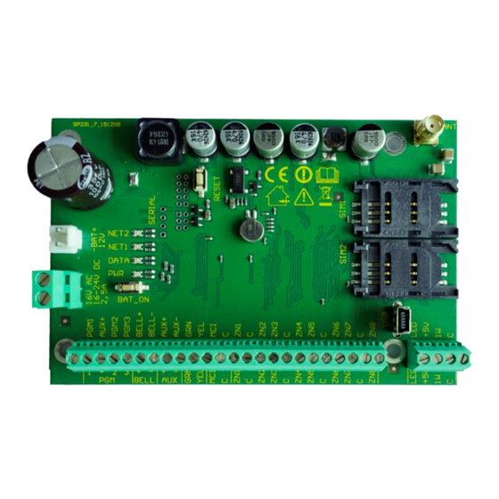
Page 9: Control Panel Structure
Control panel SP231 Control panel structure 4 Control panel structure RESET button GSM antenna port Communication and operation light indication SIM1 card holder Back-up supply port SIM2 card holder Main supply terminal block 10. USB port for configuration of the control panel... -
Page 10: Urpose Of Terminals
Control panel SP231 Control panel structure 4.1 Purpose of terminals Main supply terminal block Terminal Description 16V AC Main supply contacts shall be connected either to 16 – 18 V AC or 16 – 24 V DC 16-24V DC source. -
Page 11: System Installation
The used housing must comply with the requirements of Standard EN 60950 and EN 50131. Plastic distance holders 5.1.1.1 SP231 circuit board dimensions The figure shows the dimensions (in mm) of the control panel and its fastening holes and their locations. ©1997-2015 Trikdis www.trikdis.com... -
Page 12: Equipment Connection Sequence
4) Connect the main supply source wires to the control panel AC/DC terminals. Switch the main supply on. SP231 shall automatically recognise the correctly connected keyboards, expanders, interfaces, sensors to the 1-wire and YEL/GRN buses and shall register them in the system. - Page 13 Control panel SP231 System installation c. Users In order to control the alarm system by means of a keyboard, iButton key or phone call (SMS message), the “User” level users shall be created. Regarding creating “User” and assigning the rights to them see 6.9 “User access parameters”.
-
Page 14: Alarm System Operation Testing
Upon completion of the alarm system installation, it shall be tested for correct operation. 5.1.4.1 Walk-test function Operation of sensors and siren can be tested by carrying out a Walk-test function by using Trikdis Protegus SK130 or SK232 keyboards. The following shall be done: 1. Press the button [OK]. -
Page 15: Compatible Modules
Control panel SP231 System installation 5.2 Compatible modules Product code Purpose Current consumption Trikdis PROTEGUS 2 partitions, 32 zone LED keyboard with touch- up to 150 mA SK232LED W/B sensitive keys, white or black glass surface Trikdis PROTEGUS 16 zone LED keyboard with touch-sensitive keys,... -
Page 16: Onnection Of Smoke Detectors
Control panel SP231 System installation 5.4 Connection of smoke detectors In order to connect the control circuit of the smoke detector to the selected input, it is necessary that this input was “Fire” zone, i.e. this input must be with the set “Fire” zone function (see 6.7.1 “Main zone ”). -
Page 17: Onnection Of Report Transmission Devices
Control panel SP231 System installation Connection of remotely controlled terminals Connection of report transmission devices Report transmission devices (T10R, E10C, G10D etc.) shall be connected to a 1-wire data bus MCI. The maximum length of the bus shall be up to 100 m, with a possibility to connect up to 4 devices. -
Page 18: Onnection Of Keyboards Input Expanders
In order to connect the wireless sensors, it is necessary to connect RF- MOD module to control panel`s serial port (the newest SP231 already have soldered 4 pins plug to connect RF- MOD. For older version – solder 4 pins plug in the marked “SERIAL”... -
Page 19: Configuration Of Control Panel Operation
Windows environment. It is possible to connect to the control panel by using a USB cable or remotely, by communicating with the control panel via GPRS communication. The software is available on the website www.trikdis.com. Some control panel parameters can also be changed remotely by SMS messages. 6.1 Connect to control panel 6.1.1 Connect with USB cable... -
Page 20: Changing Of Settings By Sms Messages
Control panel SP231 Configuration of control panel operation 4) Setup an inserted SIM1 card GSM network parameters. Command to set operator parameters: PSW XXXXXX ˽ 12 ˽ APN# LOGIN# PSW### PSW XXXXXX – beginning of SMS command and its password, 12 – changing network parameters command, APN –... -
Page 21: Description Of Trikdisconfig Program
Control panel SP231 Configuration of control panel operation 6.2 Description of TrikdisConfig program Menu Main action buttons Status bar Menu Name Value Program Information about the program language and licence. Action Program control actions. Help Supplementary information about the module and the software. -
Page 22: User Access
Control Panel SP231 6.3 User access 6.3.1 Control panel configuration To set access go to the program menu System Options > System administration. Three levels for parameter configuration access are available. Upon login with the access code it can be saved by checking Remember password field. -
Page 23: Control Panel Control
The only one Master user, who is allowed to change the statuses of attributed partitions, add or delete users, change its own or other user passwords, can be in the alarm system. See "Control panel SP231. Operation manual" for control options and 6.9 User access parameters. -
Page 24: System Parameters
Control panel SP231 Configuration of control panel operation 6.5 System parameters 6.5.1 General system parameters To set general control panel operation parameters go to the program menu System options > System general. General parameters General parameters Name Description EN-50131 A box designated to set security grade of the alarm system. Upon choosing Grade 2 or... -
Page 25: Setting Of Control Panel Clock
Control panel SP231 Configuration of control panel operation 6.5.3 Setting of control panel clock The control panel sends reports with timestamps. To set the control panel clock go to System Options > System general > Timers. The control panel clock can be set automatically and stay synchronised or can be set manually. -
Page 26: System Troubles
Control panel SP231 Configuration of control panel operation 6.5.5.2 Emergency help button modes The keyboard can send emergency calls Panic, Medical, Fire. Their operation modes are to be set in System Options > System general > Keyboard Settings field, by selecting the respective mode: Silent –... -
Page 27: Tamper Recognition
Control panel SP231 Configuration of control panel operation Clock Trouble Internal-clock time is not set or set inaccurately. CMS communication Trouble Connection lost with CMS. MCI bus Module Trouble Transmitter is not detected in MCI bus. Tamper Trouble Tamper detection. -
Page 28: Control Panel Watch-Dog
Control panel SP231 Configuration of control panel operation Operation after tamper event Name Description Tamper Disable Response to tamper events is disabled. Trouble when disarmed / When disarmed, the tamper event will mean system trouble, and when armed, alarm when armed the tamper event will mean alarm. -
Page 29: Parameters Of Zone Event Reports
Control panel SP231 Configuration of control panel operation of the same zone will not be responded for the time set in Repeat. After this time expired (or when disarmed), a new count of the number of zone events will be started. -
Page 30: Zone Function Description
Control panel SP231 Configuration of control panel operation Zone report parameters Name Description Zone sequence number CID code Zone Contact ID event code (will be set automatically when the zone function is selected). Report Enable When it is checked, the event report sending will be on. - Page 31 Control panel SP231 Configuration of control panel operation Partition parameters Partition parameters Name Description Partition sequence number Partition Name Partition name. Default settings provide partition names such as Area 1, Area 2, Area 3 and etc. The name can be changed by clicking on the notation.
-
Page 32: User Access Parameters
Control panel SP231 Configuration of control panel operation 6.9 User access parameters The alarm system control options and types are indicated in the program menu Users. User access parameters User access parameters Name Description User identification number Name User name is indicated based on which in the reports sent will be visible who has controlled the alarm system and how. -
Page 33: Sim Card Parameters
Control panel SP231 Configuration of control panel operation 6.10 SIM card parameters The control panel contains two SIM card holders where SIM cards of different GSM operators could be inserted thereby enabling transmission of messages using services of different GSM communication providers. - Page 34 Control panel SP231 Configuration of control panel operation Primary communication channel Name Description Remote host Receiving device IP address. Remote port Receiving device port SMS Phone Phone number of receiving - via SMS channel -device of monitoring station is indicated...
-
Page 35: Report Transmission To User
Control panel SP231 Configuration of control panel operation Communication control parameters Name Description Encryption Key Message encryption key of six-digits which must match with message encryption key of monitoring station. Return to Period of time after expiry of which the control panel will try to restore communication primary after via primary channel, min. - Page 36 Control panel SP231 Configuration of control panel operation SMS message parameters SMS message parameters Name Description Tel 1-5 Phone numbers of users subject to message sending are entered. Enter numbers with international country code. Send SMS SMS text message sending to indicated telephone is enabled.
-
Page 37: Message Texts To User
Control panel SP231 Configuration of control panel operation Call report parameters Name Description Phone number of user subject to call receiving. Enter numbers with international country code. Dial Calling function for indicated phone number is enabled Alarm/Restore Calling in case of alarm actuation and restoration is enabled. -
Page 38: Pgm Output Configuration
Control panel SP231 Configuration of control panel operation 6.13 PGM output configuration The board contains five (PGM1 – PGM3, BELL-, LED) programmable output terminals for connection of devices controlled by the control panel. Terminals PGM1 – PGM3 are designed for connection of user selected modes, circuits. -
Page 39: Pgm Output Operation Descriptions
Control panel SP231 Configuration of control panel operation 6.13.1 PGM output operation descriptions PGM output mode Description Bell Output for connection of audible sounder (siren). After the alarm system actuation a continuous or pulse (fire) signal is generated. Buzzer Output for connection of audio indicator. - Page 40 Control panel SP231 Configuration of control panel operation b) control by phone call Pulse mode: Level mode: AC OK Output for connection of indicator about control panel supply from alternating current. Battery OK Output for connection of indicator about control panel supply from battery.
-
Page 41: Pgm Output Remote Control
Control panel SP231 Configuration of control panel operation 6.13.2 PGM output remote control When any of PGMx output is set for operating in Remote Control mode, the status of such output will be available for remote control - by SMS message or phone call. This function is used when it is needed to turn on/off home automatics by remote control (gate lifting motor, irrigation pump, heater, cooler, etc.) without changing... -
Page 42: Transmission Module Registration
Control panel SP231 Configuration of control panel operation 6.15 Transmission module registration A list of devices (slaves) connectible to MCI data bus is provided in the program menu Transmission modules. For device registration it is necessary to know MCI address number of such device; the number is to be set in the parameter configuration of respective module. -
Page 43: Keypads And Expanders Registration
6.16 Keypads and expanders registration Expansion modules physically connected to 2-wire YEL/GRN (Y/G) data bus and registered by the control panel SP231 are provided in the program menu Keypads, Expanders. The models connected for the first time will be automatically recognized and included in the list. -
Page 44: Wireless Sensors Registration
6.17 Wireless sensors registration Control panel SP231 can communicate and control UAB Trikdis distributed wireless devices via wireless RF receiver RF-MOD. Below you can find how to register wireless devices to control panel SP231 using TrikdisConfig software. Note: How to physically connect RF-MOD to SP231 go to 5.9 Connection of wireless sensors. - Page 45 Control panel SP231 Configuration of control panel operation 5) In TrikdisConfig window Wireless sensors, tab Detectors, new sensor will be shown. 6) Assign detector to the zone: new detectors will be added to the list in the window Zones, tab Zones settings.
-
Page 46: Sirens
Control panel SP231 Configuration of control panel operation Remove detector: Select detector from list, its serial number should appear in field Remove device (serial no), also it is possible to enter serial number manually. After this is done press Remove button. -
Page 47: Pendants
Control panel SP231 Configuration of control panel operation Cleaning siren`s memory: Siren are saving information about receiver in its inner memory, before learning it to new receiver, memory must be cleaned. 1) Disconnect battery. 2) Press and hold Learn button. -
Page 48: Keypad
2) Wait until indicator LED will start flash green and red in turns. 3) Memory is cleaned up. 6.17.4 Keypad Follow steps below to set Wireless Icon Keypad with Trikdis control panel SP231. Learning: 1) To start “Learn” procedure, press the button Start learning. Learning window will open. -
Page 49: Characteristics
6.18 Setting of temperature metering report characteristics Parameters required for transmission of temperature variation reports are indicated in the program menu Temperature Sensors. When temperature sensors are physically connected and power supply is on, the control panel SP231 will automatically register sensor modules. Temperature sensor parameters... -
Page 50: Setting Of Event Reports
Control panel SP231 Configuration of control panel operation 6.19 Setting of event reports The program menu Event Summary contains other - out of zone - events which, if occurred, will be reported by the control panel to the addressees in specified CID Codes and text. -
Page 51: Control Panel Firmware Upgrading
TrikdisConfig version. 2) Connect the control panel SP231 to a computer. 3) Open menu branch Firmware of parameter setting software TrikdisConfig. 4) Click Open firmware button and check SP231_xxxxxx.enc file., where xxxxxx – upgrade file version. -
Page 52: Programming And Control By Sms Messages
Control panel SP231 Programming and control by SMS messages 7 Programming and control by SMS messages The alarm system can be controlled and some parameters of the control panel can be changed by means of SMS messages. All the control panel parameters can be changed by TrikdisConfig only. - Page 53 Control panel SP231 Programming and control by SMS messages PSW – user password (up to 29 characters) PSWxxxxxx ˽ 50 ˽ N Change the status of Nth PGM output into opposite, if it is set into „Remote Control“. N values: 1, 2, 3, 4, 5.
Need help?
Do you have a question about the SP231 and is the answer not in the manual?
Questions and answers