Pyxis ST-774 User Manual
Dissolved oxygen sensor
Hide thumbs
Also See for ST-774:
- User manual (22 pages) ,
- User manual (16 pages) ,
- User manual (25 pages)
Table of Contents
Advertisement
Quick Links
Advertisement
Table of Contents

Related Manuals for Pyxis ST-774


Summary of Contents for Pyxis ST-774
- Page 2 ST-774 Dissolved Oxygen Sensor User Manual October 27, 2022 Rev. 1.2 Pyxis Lab, Inc. 1729 Majestic Dr. Suite 5 Lafayette, CO 80026 USA www.pyxis-lab.com © 2017 Pyxis Lab, Inc. Pyxis Lab Proprietary and Confidential...
-
Page 3: Table Of Contents
7.2 Adjusting 4–20mA Span ......................... 18 7.3 Communication using Modbus RTU ....................19 8 Sensor Maintenance and Precaution ..................... 20 8.1 Methods to Cleaning the ST-774 Sensor ..................20 8.2 Storage............................21 9 Troubleshooting ........................... 21 10 Contact Us ..........................21... - Page 4 A Repair Authorization (RA) Number must be obtained from Pyxis Technical Support before any product can be returned to the factory. Pyxis will pay freight charges to ship replacement or repaired products to the customer. The customer shall pay freight charges for returning products to Pyxis. Any product returned to the factory without an RA number will be returned to the customer.
-
Page 5: Introduction
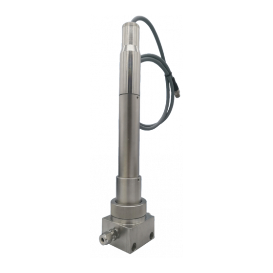
The ST-774 sensor offers an easily replaceable, front loading DO membrane cap that has been indepen- dently developed by Pyxis Lab, with a typical service life of up to two years. The flat front-end design of the ST-774 sensor makes this platform less prone to contamination or fouling and is very easy to clean. The sensor body is composed of 316L stainless steel and is well suited for aggressive industrial application use. -
Page 6: Specifications
99.999% Nitrogen Gas DO Membrane Cap Life 2 years Enclosure Rating IP-67/IP-68 Regulation CE / RoHS With Pyxis’s continuous improvement policy, these specifications are subject to change without † notice. Cables excluded ST-774 User Manual service@pyxis-lab.com | +1 (866) 203-8397... -
Page 7: Unpacking Instrument
NOTE - PO# must be issued for ST-774 Service-Swap Program. Pyxis Ships New/Reconditioned ST- 774 Sensor Only. Client Ships Their Sensor to Pyxis for Even Exchange. 30-days to Ship Old Sensor or Pyxis Bills for full value of New ST-774 ST-774 User Manual service@pyxis-lab.com... -
Page 8: Installation
4 Installation 4.1 Piping The ST-774 sensor must always be installed in sample flow at or below the upper temperature limit of the sensor (<122 °F).The sample line should always be stainless steel and utilize compression fitting adapters at all junction points to avoid oxygen ingress into the sample water. Using plastic tubing for the sample line and/or threaded-taped junctions will result in oxygen ingress and potential sensor inaccuracy or extended periods of sensor stabilization. -
Page 9: Wiring
4.3 Connecting via Bluetooth A Bluetooth adapter (P/N: MA-CR) can be used to connect a ST-774 sensor to a smart phone with the uPyxis® Mobile App or a computer with a Bluetooth/USB Adapter (P/N: MA-NEB) and the uPyxis® Desktop App. -
Page 10: Setup And Calibration With Upyxis® Mobile App
1. Open uPyxis® Mobile App. 2. On uPyxis® Mobile App, pull down to refresh the list of available Pyxis devices. 3. If the connection is successful, the ST-774 and its Serial Number (SN) will be displayed (Figure 5). 4. Press on the ST-774 sensor image. -
Page 11: Calibration Screen And Reading
NOTE Before calibrating, remove the ST-774 sensor from the water and wipe it with a damp cloth to remove debris and any fouling. If there is water on the membrane, dry it with a soft cloth taking care not to damage the membrane. - Page 12 App can be disconnected during the wait period after the ZERO calibration button has been pressed. 9) After the 12-hour period, remove the calibration cap from the ST-774 sensor and rinse the sensor tip with DI water and insert sensor back into the ST-774 Flow Cell Assembly for service.
- Page 13 The gas flow rate should be regulated between 2 and 10 liter per minute. *NOTE* Ensure the stainless-steel compression fittings are very tight and always use stainless steel OD tubing. 1) Place the sensor into the ST-774 Flow Cell Assembly. 2) Turn on a nitrogen gas flow.
-
Page 14: Device Info Screen
To perform a Cleanliness and Self-Life Check, first select the Diagnosis Condition which defines the fluid type that the ST-774 sensor in currently measuring, then press Cleanliness and Self-life Check. If the... -
Page 15: Setup And Calibration With Upyxis® Desktop App
3. On uPyxis® Desktop App, click Device → Connect via USB-Bluetooth (Figure 10). 4. If the connection is successful, the ST-774 and its Serial Number (SN) will be displayed in the left pane of the uPyxis® window. NOTE After the sensor and Bluetooth is powered up, it may take up to 10 seconds for the adapter to establish the wireless signal for communication. -
Page 16: Information Screen
Span. NOTE Before calibrating, remove the ST-774 sensor from the water and wipe it with a damp cloth to remove debris and any biofouling. If there is water on the membrane, dry it with a soft cloth taking care not to damage the membrane. - Page 17 3) Screw the lid on the vial and gently shake for 10 seconds. 4) Remove the Sulfite Zero Calibration Cap from packaging. 5) Unscrew the lid from the 10mL vial and pour the solution into the calibration cap. ST-774 User Manual service@pyxis-lab.com | +1 (866) 203-8397...
- Page 18 App can be disconnected during the wait period after the ZERO calibration button has been pressed. 9) After the 12-hour period, remove the calibration cap from the ST-774 sensor and rinse the sensor tip with DI water and insert sensor back into the ST-774 Flow Cell Assembly for service.
- Page 19 The gas flow rate should be regulated between 2 and 10 liter per minute. *NOTE* Ensure the stainless-steel compression fittings are very tight and always use stainless steel OD tubing. 1) Place the sensor into the ST-774 Flow Cell Assembly. 2) Turn on a nitrogen gas flow.
-
Page 20: Diagnosis Screen
When in the Diagnosis screen you can view the Diagnosis Condition of the device. This feature may be used for technical support when communicating with service@pyxis-lab.com. To perform a Cleanliness and Self-Life Check, first select the Diagnosis Condition which defines the fluid type that the ST-774 sensor is currently measuring, then click Cleanliness and Self-life Check. -
Page 21: Outputs
7 Outputs 7.1 4–20mA Output Setup The 4–20mA output of the ST-774 sensor is scaled as: • Dissolved Oxygen: – 4 mA = 0 ppb – 20 mA = 2000 ppb 7.2 Adjusting 4–20mA Span Users may adjust the output scale using 4–20mA Span to change the dissolved oxygen ppb value corre- sponding to the 20 mA output via uPyxis®. -
Page 22: Communication Using Modbus Rtu
Figure 16. 7.3 Communication using Modbus RTU The ST-774 sensor is configured as a Modbus slave device. In addition to the dissolved oxygen ppb value, many operational parameters, including warning and error messages, are available via a Modbus RTU con- nection. -
Page 23: Sensor Maintenance And Precaution
Figure 17. Inline Probe Cleaning Solution Kit To clean the ST-774 sensor, remove the sensor and the DO membrane cap from the water in use, wipe it with a damp cloth to remove debris and growing organisms, and use a cotton swab dipped in water to clean up the dirt on the membrane surface. -
Page 24: Storage
774 sensor from direct sunlight and precipitation. 9 Troubleshooting If the ST-774 sensor output signal is not stable and fluctuates significantly, make an additional ground con- nection — connect the black (shield, earth ground) wire to a conductor that contacts the sample water electrically such as a metal pipe adjacent to the ST-774 tee.
Need help?
Do you have a question about the ST-774 and is the answer not in the manual?
Questions and answers