Carrier WeatherMaker 38YDB Series Installation And Start-Up Instructions Manual
Two-speed split system heat pump with puron refrigeran
Hide thumbs
Also See for WeatherMaker 38YDB Series:
- Installation instructions manual (25 pages) ,
- Wiring diagram (4 pages)
Table of Contents
Advertisement
Quick Links
Visit www.carrier.com
Installation and Start-Up Instructions
NOTE: Read the entire instruction manual before starting the
installation.
This symbol → indicates a change since the last issue.
SAFETY CONSIDERATIONS
Improper installation, adjustment, alteration, service, maintenance,
or use can cause explosion, fire, electrical shock, or other
conditions which may cause death, personal injury, or property
damage. Consult a qualified installer, service agency, or your
distributor or branch for information or assistance. The qualified
installer or agency must use factory-authorized kits or accessories
when modifying this product. Refer to the individual instructions
packaged with the kits or accessories when installing.
Follow all safety codes. Wear safety glasses, protective clothing,
and work gloves. Use quenching cloth for brazing operations.
Have fire extinguisher available. Read these instructions thor-
oughly and follow all warnings or cautions included in literature
and attached to the unit. Consult local building codes and National
Electrical Code (NEC) for special requirements.
Recognize safety information. This is the safety-alert symbol
When you see this symbol on the unit and in instructions or
manuals, be alert to the potential for personal injury.
Understand the signal words DANGER, WARNING, CAUTION,
and NOTE. These words are used with the safety-alert symbol.
DANGER identifies the most serious hazards which will result in
severe personal injury or death.
WARNING signifies hazards which could result in personal injury
or death. CAUTION is used to identify unsafe practices which
would result in minor personal injury or product and property
damage. NOTE is used to highlight suggestions which will result
in enhanced installation, reliability, or operation.
Before installing, modifying, or servicing system, main elec-
trical disconnect switch must be in the OFF position. There
may be more than 1 disconnect switch. Lock out and tag
switch with a suitable warning label. Electrical shock can
cause personal injury or death.
Puron® (R-410A) systems operate at higher pressures than
standard R-22 systems. Be certain that service equipment is
rated for R-410A. Some R-22 service equipment may not be
acceptable. Check with your distributor.
INSTALLATION RECOMMENDATIONS
NOTE: In some cases noise in the living area has been traced to
gas pulsations from improper installation of equipment.
1. Locate unit away from windows, patios, decks, etc. where unit
operation sound may disturb customer.
2. Ensure that vapor and liquid tube diameters are appropriate to
capacity of unit.
Manufacturer reserves the right to discontinue, or change at any time, specifications or designs without notice and without incurring obligations.
Book 1 4
PC 101
Catalog No. 533-80046
Tab 5a 5a
WeatherMaker™ Two-Speed Split System
Heat Pump with Puron® Refrigerant
.
3. Run refrigerant tubes as directly as possible by avoiding
unnecessary turns and bends.
4. When passing refrigerant tubes through the wall, seal opening
with RTV or other pliable silicon-based caulk. (See Fig. 2.)
5. Avoid direct tubing contact with water pipes, duct work, floor
joists, wall studs, floors, and walls, and brick.
6. Do not suspend refrigerant tubing from joists and studs with a
rigid wire or strap which comes in direct contact with tubing.
(See Fig. 2.)
7. When necessary, use hanger straps which are 1 in. wide and
conform to shape of tubing insulation. (See Fig. 2.)
8. Isolate hanger straps from insulation by using metal sleeves
bent to conform to shape of insulation.
9. Ensure that tubing insulation is pliable and completely sur-
rounds vapor tube.
Outdoor unit contains system refrigerant charge for operation with
indoor unit of the same size when connected by 15 ft of
field-supplied or factory accessory tubing. For proper unit opera-
tion, check refrigerant charge using charging information located
on control box cover or in the Check Charge section of this
instruction.
IMPORTANT: Maximum liquid-line size is 3/8–in. O.D. for all
residential applications.
IMPORTANT: Only install the factory-supplied Puron® heat
pump (bi-flow) liquid line filter drier. Obtain replacement filter
driers from your local distributor.
Printed in U.S.A.
Form 38YDB-3SI
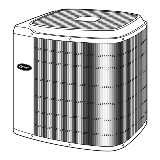
Fig. 1—Model 38YDB
Pg 1
11-01
Replaces: 38YDB-2SI
38YDB
A98516
Advertisement
Table of Contents

Related Manuals for Carrier WeatherMaker 38YDB Series


Summary of Contents for Carrier WeatherMaker 38YDB Series
- Page 1 38YDB WeatherMaker™ Two-Speed Split System Heat Pump with Puron® Refrigerant Visit www.carrier.com Installation and Start-Up Instructions NOTE: Read the entire instruction manual before starting the installation. This symbol → indicates a change since the last issue. SAFETY CONSIDERATIONS Improper installation, adjustment, alteration, service, maintenance,...
-
Page 2: Installation
NOTE: Avoid contact between tubing and structure 3 /8 - IN. DIA TIEDOWN KNOCKOUTS IN BASEPAN (2) PLACES OUTDOOR WALL INDOOR WALL CAULK LIQUID TUBE VAPOR TUBE INSULATION THROUGH THE WALL JOIST ″ VIEW FROM TOP HANGER STRAP (AROUND VAPOR INSULATION TUBE ONLY) A97548... -
Page 3: Fan Coils
Step 6—Check Indoor Expansion Device 10. Attach TXV bulb to horizontal section of suction line using bulb strap provided. (See Fig. 6C.) Insulate bulb with factory- supplied insulation tape (See Fig. 6E). See Fig. 7 for correct positioning of sensing bulb. For proper unit operation and reliability, units must be installed with factory-supplied balance port hard shutoff TXV 11. - Page 4 size and condition. Tubing diameters listed in Table 1 are adequate for equivalent lengths up to 50 ft. For tubing requirements beyond SENSING BULB 50 ft, substantial capacity and performance losses will occur. Follow the recommendations in the Application Guideline and Service Manual—Air Conditioners and Heat Pumps Using Pu- STRAP ron®...
- Page 5 Table 2—Accessory Usage REQUIRED FOR LONG-LINE REQUIRED FOR ACCESSORY APPLICATIONS SEACOAST APPLICATIONS (OVER 50 FT) (WITHIN 2 MILES) Coastal Filter Support Feet Recommended Puron® Balance-Port Hard Shutoff TXV Yes† Yes† Puron® Liquid-Line Solenoid Valve for Heating KHALS0401LLS * For tubing line sets between 50 and 175 ft horizontal or 20 ft vertical differential refer to Application Guideline and Service Manual—Air Conditioners and Heat Pumps Using Puron®...
- Page 6 NOTE: Operation of unit on improper line voltage constitutes Step 9—Install Electrical Accessories abuse and could affect unit reliability. See unit rating plate. Do not GENERAL install unit in system where voltage may fluctuate above or below Refer to the individual instructions packaged with kits or acces- permissible limits.
-
Page 7: Unit Charge
If pressure and temperature do not match on chart, system NOTE: Carrier electronic thermostats are equipped with a 15- refrigerant charge may not be correct. Do not use chart to adjust minute staging timer. This timer prevents the dual capacity system refrigerant charge. -
Page 8: Cooling Operation
COOLING OPERATION Table 3—Required Liquid-Line Temperature (°F) This product utilizes a 2-stage cooling indoor thermostat. With a REQUIRED SUBCOOLING TEMPERATURE LIQUID PRESSURE AT call for first stage cooling (Yl), the outdoor fan and low capacity (°F) SERVICE VALVE compressor are energized. If low capacity cannot satisfy cooling (PSIG) demand, high capacity is energized (Yl and Y2 or just Y2) by the second stage of indoor thermostat. - Page 9 PROGRAMMABLE 40FK/FV4 THERMIDISTAT TWO-SPEED THERMOSTAT CONTROL SINGLE-STAGE TWO-SPEED HEAT PUMP HEAT PUMP MODEL 2S FAN COIL MODEL RH FURNACE RVS COOLING O/ W2 JUMPER COOL/HEAT 24 VAC HOT Y1/W2 STAGE 1 W/W1 HEAT STAGE 3 COOL/HEAT COOL/HEAT Y/Y2 Y1/W2 STAGE 2 STAGE 1 RVS COOLING O/W2...
- Page 10 THERMIDISTAT PROGRAMMABLE VARIABLE VARIABLE-SPEED CONTROL CONDENSING TWO-SPEED DUAL FUEL SPEED THERMOSTAT CONDENSING TWO-SPEED MODEL RH FURNACE HEAT PUMP MODEL DF FURNACE HEAT PUMP RVS COOLING O/W2 24 VAC HOT COOL/HEAT Y1/W2 STAGE 1 W/W1 HEAT STAGE 3 W/W1 HEAT STAGE 3 W/ W1 W/ W1 (FURNACE)
- Page 11 LEGEND 24 VOLT FACTORY WIRING 24 VOLT FIELD WIRING FIELD SPLICE CONNECTION RELAY SPDT, PILOT DUTY 24-V COIL (HN61KK324) OR EQUIVALENT HUMIDISTAT, OPENS ON HUMIDITY RISE (HL38MG026) AIRFLOW SELECTOR A01222 WIRING DIAGRAM NOTES: 1. Wiring must conform to NEC or local codes. 2.
- Page 12 • compressor internal overload trip (refer to Table 7 for correct Table 4—LED Control Function Light Code winding resistance) CODE DEFINITION • no 208/230 volt power supply to outdoor unit Constant flash No demand • failed compressor contactor(s) No pause Stand by •...
-
Page 13: Care And Maintenance
Table 6—Factory Defaults FAILED COMPONENT FUNCTION DEFAULT Defrost is initiated based on coil Defrost Initiation temperature and time. Ambient Thermistor One minute fan off delay in cooling No delay function greater than or equal to 100°F Defrost occurs at each time interval, but Outdoor Coil Thermistor Defrost Initiation and Termination terminate after 5 minutes... - Page 14 Control Box Side of Unit THERMISTOR PLACED UNDERNEATH BASE PAN (ATTACHED TO BASE PAN WITH ADHESIVE) A00430 Fig. 16—View from Top of Base Pan DUAL CAPACITY CONNECTION DIAGRAM 208 / 230 - 1 - 60 POWER SUPPLY EQUIP GND NOTE #11 COMP HP/ AC SE V...
- Page 15 DUAL CAPACITY CONNECTION DIAGRAM 208 / 230 - 1 - 60 POWER SUPPLY EQUIP GND NOTE #10 COMP HP/AC START YEL/PNK FORCED COMP YEL/PNK DEFROST BLU/PNK PWM 2 BLU/PNK DEFROST PWM 1 TIME (MIN) -t° -t° START RELAY COMM STATUS GRN/YEL A B C D TO INDOOR UNIT...
- Page 16 Copyright 2001 CARRIER Corp. • 7310 W. Morris St. • Indianapolis, IN 46231 38ydb3si Manufacturer reserves the right to discontinue, or change at any time, specifications or designs without notice and without incurring obligations. Book 1 4 PC 101 Catalog No. 533-80046 Printed in U.S.A.
Need help?
Do you have a question about the WeatherMaker 38YDB Series and is the answer not in the manual?
Questions and answers