Table of Contents
Advertisement
Quick Links
Advertisement
Table of Contents

Related Manuals for Parker DCP3


Summary of Contents for Parker DCP3
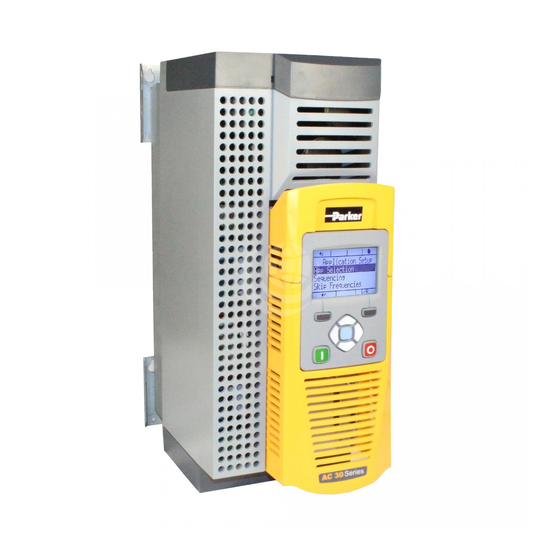
- Page 1 Drive Controlled Pump Installation Manual DCP3...
- Page 2 The user must analyze all aspects of the application, follow applicable industry standards, and follow the information concerning the product in the current product catalog and in any other materials provided from Parker or its subsidiaries or authorized distributors.
-
Page 3: Table Of Contents
Manual Drive Controlled Pump Content Page Safety Introduction Initial steps • Installation • Operation • Programming (Parker Drive Quicktool) – • pc programming tool • PC requirements • The Graphical Keypad Power ratings Construction Mounting • Cubicle Mount Mounting •... - Page 4 • Fitting a remote GKP • The Display • Keys • Soft key action indication • Menu Organisation Parker Drive Quicktool (PDQ) PC-Software • Installation • Starting the wizard • Task selection Parameter description Parameter list Trips and Fault Finding Technical data •...
-
Page 5: Safety
DC bus and the brake, where fitted) when the motor dismantled. In the event of a fault the drive must be is at standstill or is stopped. returned. Refer to "Routine Maintenance and Repair". DCP Manual innen A4 UK.indd 06.11.17 Parker Hannifin Corporation Hydraulics Group... - Page 6 • Stored energy might not discharge to safe levels as • Unintended operation quickly as suggested, and can still be present even though the drive appears to be switched off DCP Manual innen A4 UK.indd 06.11.17 Parker Hannifin Corporation Hydraulics Group...
-
Page 7: Introduction
• Windows 7 (32 & 64 bit) Know your application: • Windows 8 (32 & 64 bit) • Install the Parker Drive Quicktool (PDQ) after down- loading it from www.parker.com/ssd/pdq • Connect your pc to your Drive via Ethernet • Commission your Drive with the Parker Drive Quick- tool wizard •... -
Page 8: Power Ratings
DCP3 DCP3 DCP3 DCP3 DCP3 DCP3 DCP3 DCP3 DCP3 DCP3 DCP3 DCP3 DCP3 DCP3 DCP3 DCP3 Product overview Product Range AC30V FRAME D, E, F, G, H, J, K DCP Manual innen A4 UK.indd 06.11.17 Parker Hannifin Corporation Hydraulics Group... -
Page 9: Construction
Size H 42.8 kg M6 fixings 9.0 mm slots & holes Size J 89 kg M6 fixings Size K 125 kg 1310 1282 M10 fixings All dimensions are in millimetres DCP Manual innen A4 UK.indd 06.11.17 Parker Hannifin Corporation Hydraulics Group... -
Page 10: Mounting The Drive
Air Clearance for a Cubicle Mount Product/Application, Frame D Illustrated. Clearances for IP20 Product (mm) Size D–H 75 minimum (excludes cabling requirements) Size J 100 minimum (excludes cabling requirements) Size K DCP Manual innen A4 UK.indd 06.11.17 Parker Hannifin Corporation Hydraulics Group... -
Page 11: Mounting Brackets
Cubicle mounting details (all frame size) Series AC30V Rear view showing fixing holes for cubicle mount Fixing holes Note: Frame H, J and K have a single mounting plate which cannot be moved. DCP Manual innen A4 UK.indd 06.11.17 Parker Hannifin Corporation Hydraulics Group... -
Page 12: Through Panel Mount
455.8 195.8 Use M5 fixings Size H Use M6 fixings Size J 12.5 242.6 All dimensions are in millimetres Through panel installation for frame size K is not possible. DCP Manual innen A4 UK.indd 06.11.17 Parker Hannifin Corporation Hydraulics Group... -
Page 13: Through Panel Mounting Details (All Frame Sizes)
5. Fit gasket to the drive so that an air-tight seal will be made between the drive and the panel. Through Panel Kits, can be purchased from Parker using the following part numbers: Size D – LA502668 6. Tighten all screws in place as shown, according to panel Size E –... -
Page 14: Cabling Bracket For Control & Main Cable
With the bottom cover off you can screw the cabling the braking terminals brackets in place, if required. The cabling brackets are standard with C2 filtering products and can also be obtained from Parker using Upper the following part numbers: Terminal Cover Size D –... -
Page 15: Installation
Tighten all terminals to the correct tightening torque; refer to the Terminal Tight- ening Torques table. DCP Manual innen A4 UK.indd 06.11.17 Parker Hannifin Corporation Hydraulics Group... - Page 16 Isolate supply before plugging or unplugging control unit to the power stack. 1. Unscrew captive screw. 2. Lift lower edge of assembly. 3. Slide assembly upwards, as far as possible, to unlatch from unit. DCP Manual innen A4 UK.indd 06.11.17 Parker Hannifin Corporation Hydraulics Group...
-
Page 17: Control Wiring Connections
X13/06 0V AUX input X14/01 (BOT) Relay 01 (contact A) X14/02 Relay 01 (contact B) X14/03 Relay 02 (contact A) X14/04 Relay 02 (contact B) Control Wiring Layout Diagram DCP Manual innen A4 UK.indd 06.11.17 Parker Hannifin Corporation Hydraulics Group... -
Page 18: Inputs - Analogue (Dcp3Xxxa)
LS Control Accumulator Control Start Drive No Stop Reset Pump 1 on/off Switch on signal Pump 2 on/off Switch off signal 5..15 reserved Not required (can be used to display) DCP Manual innen A4 UK.indd 06.11.17 Parker Hannifin Corporation Hydraulics Group... -
Page 19: Outputs - Analogue (Dcp3Xxxa)
Pressure reached reserved 5..15 reserved If internal speed setpoint < minimum speed then DIGOUT 03 = TRUE else FALSE, can be used to control a bypass valve (not included) DCP Manual innen A4 UK.indd 06.11.17 Parker Hannifin Corporation Hydraulics Group... -
Page 20: Option Modules
X20/05 Input 10 % DOUT11 to DOUT14. See the notes below. 0 V reference for digital inputs X20/06 DIG 0V and outputs. See the notes below. DCP Manual innen A4 UK.indd 06.11.17 Parker Hannifin Corporation Hydraulics Group... -
Page 21: Analogue Inputs
0 to between these two 4.5 kΩ X22/02 terminals. Example: Motor Thermistor Terminal Name Range Description X22/01 Connect motor thermistor 0 to between these two 4.5 kΩ X22/02 terminals. DCP Manual innen A4 UK.indd 06.11.17 Parker Hannifin Corporation Hydraulics Group... - Page 22 Cable Screen X24/08 Cable Screen Note: The encoder power supply is fully isolated from the drive internal circuits and from the encoder inputs on X24 ter- minals 01 to 04. DCP Manual innen A4 UK.indd 06.11.17 Parker Hannifin Corporation Hydraulics Group...
-
Page 23: Ethernet
TRUE. on the GKP status bar. The parameter 0936 Setting Lock, when set to TRUE, pre- vents a configuration tool from modifying the IP settings. DCP Manual innen A4 UK.indd 06.11.17 Parker Hannifin Corporation Hydraulics Group... -
Page 24: Manually Setting The Ip Address
The AC30 will take a link-local address in the range 169.254.*.* if no DHCP server is discovered on the network. If a DHCP server is available (or becomes subsequently available) then the AC30 will take the IP address from the server. Note that the DHCP has precedence. DCP Manual innen A4 UK.indd 06.11.17 Parker Hannifin Corporation Hydraulics Group... -
Page 25: Profibus Communication With S7
Profibus communication with Siemens S7 Cyclic communication Acyclic communication - Copy SFB52 to write and SFB53 to read from the internal library - Define DBs as instances from SFB52 and SFB53 DCP Manual innen A4 UK.indd 06.11.17 Parker Hannifin Corporation Hydraulics Group... - Page 26 – Click on the DP master system – Reading diagnostic ID – INDEX is always 255 – LEN contains the size of record – RECORD should be set as shown DCP Manual innen A4 UK.indd 06.11.17 Parker Hannifin Corporation Hydraulics Group...
- Page 27 – Parameter number is written to MB34 and MB35 – Here 1928 (INT) 788 (hex) – Value is written to MB36 - MB39 – Here 31.5 (IEEE754) 41FC (hex) DCP Manual innen A4 UK.indd 06.11.17 Parker Hannifin Corporation Hydraulics Group...
-
Page 28: Sto Functional Description
For these activities recognised electrical power isolation devices and lock-off procedures should be used. The AC30V STO function is a factory-fitted and factory-tested feature. DCP Manual innen A4 UK.indd 06.11.17 Parker Hannifin Corporation Hydraulics Group... -
Page 29: User Connections
Don’t care Don’t care Drive cannot start or supply power to its motor. Do not connect both X10/02 and X10/4 to earth, otherwise an earth loop could be created. DCP Manual innen A4 UK.indd 06.11.17 Parker Hannifin Corporation Hydraulics Group... -
Page 30: Applications That Do Not Require Sto Function
24VDC with respect to terminals X10/02 or X10/04. • Supports variable and fixed displacement pumps STO Status output on X10/05 and X10/06 may be left • Drive parameter settings for Parker-pumps(v, n disconnected. , …) by order code • Integrated control of optional bypass valve (on/off) and All wiring shown is within the control cubicle. -
Page 31: Volume Flow Control (Q Control)
DIGOUT 11 (X20/01) Pressure reached Filter Actual pressure ANIN01 (X11/01) Filter min/max Pressure Setpoint Motor ANIN11(X21/02) Control ANOUT01(X11/03) Actual Motor Speed Filter Flow Setpoint Leakage ANIN02(X11/02) Comp. ANOUT02(X11/04) CMD pressure valve DCP Manual innen A4 UK.indd 06.11.17 Parker Hannifin Corporation Hydraulics Group... -
Page 32: The Graphical Keypad
Use M3 x 10 self tapping screws. Connection lead RS232/REM OPSTA with a Steward 28A2025-OAO connector. Gasket All measurements in millimeter. Reverse side of the GKP DCP Manual innen A4 UK.indd 06.11.17 Parker Hannifin Corporation Hydraulics Group... -
Page 33: The Display
Navigation Displays the previous level’s menu LEFT Edit Selects the digit to be changed Navigation Displays the next menu level or parameter RIGHT Edit Selects the digit to be changed DCP Manual innen A4 UK.indd 06.11.17 Parker Hannifin Corporation Hydraulics Group... -
Page 34: Soft Key Action Indication
In this case the re- turn is the opposite of the OK key. When changing a parameter value the Abort key discards any modifications and leaves the parameter unchanged. DCP Manual innen A4 UK.indd 06.11.17 Parker Hannifin Corporation Hydraulics Group... -
Page 35: Menu Organisation
Controller Status Controller Status Controller Status Controller Status Speed Loop Ctrl Speed Loop Speed Loop Speed Loop Speed Loop HPU Messages Ctrl Ctrl Ctrl Ctrl HPU Messages HPU Messages HPU Messages HPU Messages DCP Manual innen A4 UK.indd 06.11.17 Parker Hannifin Corporation Hydraulics Group... - Page 36 1991 1949 Pressure Valve Max p Pressure Switch Off pressure 1990 1950 Valve Feed Forward Max p Pressure 1991 1990 Pressure Valve Valve Feed Forward Pres- 1991 sure Valve DCP Manual innen A4 UK.indd 06.11.17 Parker Hannifin Corporation Hydraulics Group...
-
Page 37: Parker Drive Quicktool (Pdq) Pc-Software
2056 Rate Feedback 2056 Rate Feedback 2056 Rate Feedback Parker Drive Quicktool (PDQ) Installation Launch the installer, setup.exe, from the latest version from www.parker.com/ssd/pdq Follow the steps of the InstallShield Wizard. DCP Manual innen A4 UK.indd 06.11.17 Parker Hannifin Corporation Hydraulics Group... -
Page 38: Starting The Wizard
Starting the wizard Once the InstallShield completes, run the PDQ from the “Start” menu as shown or from the desktop shortcut. Requires an Ethernet connection → PC to Drive Task selection DCP Manual innen A4 UK.indd 06.11.17 Parker Hannifin Corporation Hydraulics Group... - Page 39 Ensure you have selected the correct Drive before continuing. If Drive Brake Switch is not fitted it will be indicted by the symbol as shown in Figure 9-5. DCP Manual innen A4 UK.indd 06.11.17 Parker Hannifin Corporation Hydraulics Group...
- Page 40 Manual Drive Controlled Pump Open DCP application Select application DCP Manual innen A4 UK.indd 06.11.17 Parker Hannifin Corporation Hydraulics Group...
- Page 41 Setup DCP application Parameter can be set by clicking the appropriate icon. Setup motor, drive control, IOs and communication Set customer specific motor data, control strategy, I/Os and communication. DCP Manual innen A4 UK.indd 06.11.17 Parker Hannifin Corporation Hydraulics Group...
- Page 42 At this step the settings are whrite to the drive. A drive name can be set to. Monitor and optimize the drive At parameter the optimization parameters can be set. DCP Manual innen A4 UK.indd 06.11.17 Parker Hannifin Corporation Hydraulics Group...
- Page 43 Under application can view the history and state of active application. Monitor and optimize the drive Under scope can viewed and stored the profile of parameters. Export as excel file is possible. DCP Manual innen A4 UK.indd 06.11.17 Parker Hannifin Corporation Hydraulics Group...
-
Page 44: Parameter Description
(e.g. via the digital input), the pressure is set to p = 300 Bar.) max. pressure is set to p = The DCP code needs to be 300 Bar.) set to default (DCPxxxxxxx xxxxA0000). DCP Manual innen A4 UK.indd 06.11.17 Parker Hannifin Corporation Hydraulics Group... - Page 45 1 or 2. DCP Manual innen A4 UK.indd 06.11.17 Parker Hannifin Corporation Hydraulics Group...
- Page 46 This parameter shows the ac- Defines the max. pressure for sure setpoint for LS control. tual pressure difference (p0 tual pressure pLS at AIN02. 100% input signal at ANIN02. – pLS). DCP Manual innen A4 UK.indd 06.11.17 Parker Hannifin Corporation Hydraulics Group...
- Page 47 If the pressure relief valve opens before the drive has reached the minimum speed, the feed forward gain has to be increased. DCP Manual innen A4 UK.indd 06.11.17 Parker Hannifin Corporation Hydraulics Group...
- Page 48 Monitor::Application:: Fieldbus 2021 2022 Parameter name Control Word Status Word Parameter Control Word Status Word description Function This parameter displays the actual controlword. This parameter displays the actual statusword. DCP Manual innen A4 UK.indd 06.11.17 Parker Hannifin Corporation Hydraulics Group...
- Page 49 This value displays the actual error status. from overheating at min. speed. After the elapsed time at min. speed, the drive stopps. If the time is set to 0s, the function is switched off. DCP Manual innen A4 UK.indd 06.11.17 Parker Hannifin Corporation Hydraulics Group...
- Page 50 This value is set to TRUE, if This value is set to TRUE, if the warning of the oil temper- the error of the oil tempera- ature is active. ture is active. DCP Manual innen A4 UK.indd 06.11.17 Parker Hannifin Corporation Hydraulics Group...
-
Page 51: Parameter List
0 to 10000 ALWAYS p, p/Q. LS Setup::Application::LS Control Setup::Application::Analog Input p 1937 P amx at 100% Setup::Application::Analog Input pQ REAL 0 to 500 ALWAYS p, p/Q. LS Setup::Application::Analog Input LS DCP Manual innen A4 UK.indd 06.11.17 Parker Hannifin Corporation Hydraulics Group... - Page 52 Monitor::Application::p/Q Control REAL -100 0 to 100 ALWAYS p, p/Q, LS Monitor::Application::LS Control Monitor::Application::p Control 1977 Rate Feedback Monitor::Application::p/Q Control REAL -10 to 10 ALWAYS p, p/Q, LS Monitor::Application::LS Control DCP Manual innen A4 UK.indd 06.11.17 Parker Hannifin Corporation Hydraulics Group...
- Page 53 0 - 400 ALWAYS 2042 P2 Testmovement Monitor::Application::Testfunction REAL 0 - 400 ALWAYS 2043 Q1 Testmovement Monitor::Application::Testfunction REAL 0 - 1000 ALWAYS 2044 Q2 Testmovement Monitor::Application::Testfunction REAL 0 - 1000 ALWAYS DCP Manual innen A4 UK.indd 06.11.17 Parker Hannifin Corporation Hydraulics Group...
-
Page 54: Trips And Fault Finding
A trip can only be reset once the trip condition is no lon- ger active, i.e. a trip due to a heatsink over-temperature will not reset until the temperature is below the trip level. DCP Manual innen A4 UK.indd 06.11.17 Parker Hannifin Corporation Hydraulics Group... - Page 55 Trying to decelerate a large inertia too quickly or too often Keypad has been disconnected from drive whilst drive is running in Local Control: LOCAL CONTROL · GKP accidentally disconnected from drive DCP Manual innen A4 UK.indd 06.11.17 Parker Hannifin Corporation Hydraulics Group...
- Page 56 Pulse Encoder IO Option, but the IO Option has not been correctly configured. An internal cooling fan has failed. This will reduce the lifetime of the power electronics. INTERNAL FAN FAIL · Return the power stack to a Parker Hannifin repair centre. Current feedback phase missing CURRENT SENSOR ·...
- Page 57 Replace the IO option 1504 IO Option watchdog · The IO Option has become disconnected 1601 Stack internal fault · Return the power stack to Parker Hannifin repair center. DCP Manual innen A4 UK.indd 06.11.17 Parker Hannifin Corporation Hydraulics Group...
-
Page 58: Fault Finding
HEALTH LED RUN LED STOPPED RUNNING STOPPING, (NORMAL) QUICKSTOPPING FAULTED INITIALISING CONFIGURATION MODE CONFIGURATION FAULT FIRMWARE UPDATE – Idle FIRMWARE UPDATE – Erasing firmware FIRMWARE UPDATE – Writing firmware DCP Manual innen A4 UK.indd 06.11.17 Parker Hannifin Corporation Hydraulics Group... -
Page 59: Technical Data
TN and IT (non-earth referenced) supplies. Prospective Short Circuit Cur- Refer to the appropriate Electrical Ratings table. rent (PSCC) Earth Leakage Current >10mA (all models) DCP Manual innen A4 UK.indd 06.11.17 Parker Hannifin Corporation Hydraulics Group... -
Page 60: Electrical Ratings (400 V Build Variant)
4 / 16 3.8 % 3 PS DCP3010 3 kW 97 % 4 / 16 3.8 % 4 kW 10.0 DCP3012 97 % 4 / 16 3.3 % 5 PS DCP Manual innen A4 UK.indd 06.11.17 Parker Hannifin Corporation Hydraulics Group... - Page 61 3 / 12 5.3 % 25Hp 30.5 22kW 41.8 DCP3060 98 % 3 / 12 5.7 % 30Hp 37.5 30kW 54.7 DCP3073 98 % 3 / 12 5.2 % 40Hp DCP Manual innen A4 UK.indd 06.11.17 Parker Hannifin Corporation Hydraulics Group...
- Page 62 DCP3180 98 % 2.5 / 8 7.5 % 100Hp 90kW DCP3205 98 % 2.5 / 8 8.6 % 125Hp 110kW DCP3260 98 % 2.5 / 8 8.0 % 150Hp DCP Manual innen A4 UK.indd 06.11.17 Parker Hannifin Corporation Hydraulics Group...
- Page 63 DCP3073 100A DCP3087 125A 125A DCP3105 150A 150A DCP3145 200A 200A DCP3180 250A 250A DCP3205 315A 315A DCP3260 400A 400A DCP3315 400A 400A DCP3380 500A 500A DCP3440 630A 630A DCP Manual innen A4 UK.indd 06.11.17 Parker Hannifin Corporation Hydraulics Group...
-
Page 64: Internal Brake Switch
90 / 125 112.5 / 150 75 / 100 DCP3205 110 / 150 135 / 187.5 90 / 125 DCP3260 132 / 200 165 / 225 110 / 150 3.55 DCP Manual innen A4 UK.indd 06.11.17 Parker Hannifin Corporation Hydraulics Group... -
Page 65: Analogue Inputs/Outputs
(absolute maximum input voltage ±30 VDC) Input Threshold Typically 10 V Input Impedance 3.3 kW Input Current 7.3 mA ± 10% @ 24 V Sample Interval 1 ms DCP Manual innen A4 UK.indd 06.11.17 Parker Hannifin Corporation Hydraulics Group... -
Page 66: Digital Outputs
RL1 (X14/01) – X14/02), RL2 (X14/03) – X14/04) These are volt-free relay contacts 250V ac or 30V dc Maximum Voltage Protection against inductive or capacitive loads must be provided externally. Maximum Current 3A resistive load DCP Manual innen A4 UK.indd 06.11.17 Parker Hannifin Corporation Hydraulics Group... -
Page 67: Configure The Drive
Qmax at 100% AIN02: Qmax at 100% input at analogue input 02. Displacement ccm*100 % Speed rpm Qmax= 1000 If the target-flow is sent via fieldbus, this pa- rameter is not required. DCP Manual innen A4 UK.indd 06.11.17 Parker Hannifin Corporation Hydraulics Group... -
Page 68: Set Of Motor Data
1: 1932 (Actual pressure) be an error. 2: 1919 (Actual flow) 3: 0393 (Actual speed) Motor name plate Base Frequency Rated Motor Current Motor poles Base voltage Nameplate speed DCP Manual innen A4 UK.indd 06.11.17 Parker Hannifin Corporation Hydraulics Group... -
Page 69: Commissioning The Drive
Manual Drive Controlled Pump Commissioning the drive Perform signal check Control Screen: Check Target and Actual Values for Pressure and Flow Inputs and Outputs: Check digital and analogue In-/Outputs DCP Manual innen A4 UK.indd 06.11.17 Parker Hannifin Corporation Hydraulics Group... - Page 70 Manual Drive Controlled Pump To optimize the drive, please use the Quick Monitor Change parameter values DCP Manual innen A4 UK.indd 06.11.17 Parker Hannifin Corporation Hydraulics Group...
- Page 71 ZA – South Africa, Kempton Park Tel: +27 (0)11 961 0700 Tel: +52 72 2275 4200 parker.southafrica@parker.com © 2017 Parker Hannifin Corporation. All rights reserved. HY11-5715-707/UK, 01/2017 EMEA Product Information Centre Free phone: 00 800 27 27 5374 (from AT, BE, CH, CZ, DE, DK, EE, ES, FI, FR, IE, IL,...
Need help?
Do you have a question about the DCP3 and is the answer not in the manual?
Questions and answers