Table of Contents
Advertisement
Advertisement
Table of Contents

Subscribe to Our Youtube Channel
Related Manuals for RS PRO RSDPB5000 Series


Summary of Contents for RS PRO RSDPB5000 Series
- Page 1 Quick Start RSDPB5000/RSDPB4000 High Voltage Differential Probe Series...
- Page 3 Please read this manual carefully before use Safety precautions Be cautious of an electric shock Pay attention to the maximum input voltage Please do not use in humid or in flammable and explosive environment...
- Page 4 50X/500X RSDPB5150 Overview RSDPB5000 series high voltage differential probes are designed for the measurement of high voltage differential signal, to meet the demand for floating measurement. The bandwidth can be as high as 100MHz, meeting the demand for majority of measurement systems.
-
Page 5: Detailed Description
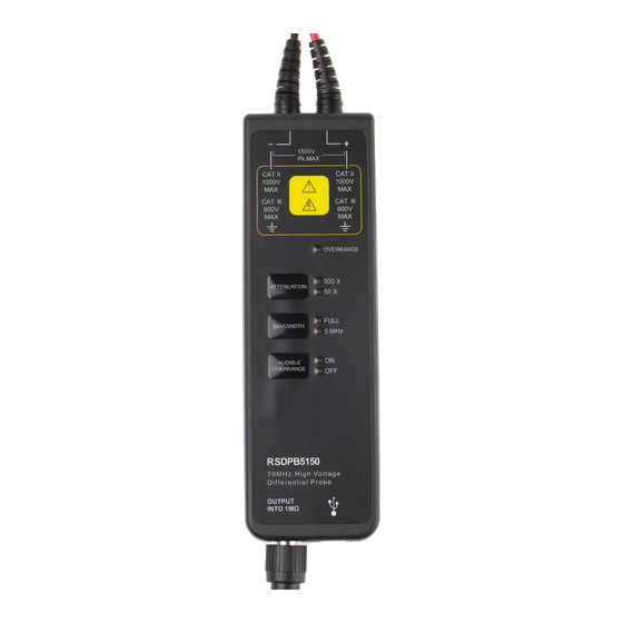
Product and Accessories Description Probe body description Take RSDPB5150 as an example, voltage, range and bandwidth are varied with different products. Input Port Maximum differential Voltage 1500V Danger! High Voltage! Commom-mode Voltage Security Level Overrange Indicator Attenuation Button Attenuation Indicator Bandwidth Limit Button Bandwidth Limit Indicator Audible Overrange Button... -
Page 6: Acce Ssories Description
BANDWIDTH: The series products have bandwidth selection function. The default is full bandwidth(FULL) of the product. When testing low frequency signal, you can choose 5MHz bandwidth limit to prevent being interfered by high frequency signal. AUDIBLE OVERRANGE: When the test range exceeds probe range, audible and visual alarm will start. - Page 7 Coaxial Output Line (CK-310) Coaxial Output Line (CK-320) USB line (CK-315 AM-BM, 1.5m) Power adapter (CK-605) USB 5V/1A Product standard accessories description RSDPB5150 Model CATIII 1000V Alligator Clips (CK-261) CATIV 600V Alligator Clips (CK-262) ----- CATIII 1000V Pincer Clips (CK-281 ) CATIII 1000V Hook Clips (CK-284 ) High...
-
Page 8: Electric Specification
Electric Specification RSDPB5150 Model DC-70MHz BW(-3dB) ≤5ns Rise time ±2% Accuracy 50X/500X Attenuation Rate 100X/1000X 50X:150V 100X:700V Max Differential Test Voltage (DC + Peak AC) 500X:1500V 1000X:7000V Max input common mode voltage( voltage-to-earth 600V CATIII Vrms) 1000V CATII Single-ended to ground 5MΩ... -
Page 9: Mechanical Specification
Mechanical Specification RSDPB5150 Model CK-28 Approx 28 cm Differential Input lead CK-310 Approx 1 m Output Lead Approx 2 m CK-320 Approx 85*40*17 mm Alligator Clips CK-261 Approx 106*43*16 mm Alligator Clips CK-261 Approx 152*50*13 mm Pincer Clips CK-281 Approx 121*23*23 mm Hook Clips CK-284 195*65*28 mm Probe body dimensions... -
Page 10: Operating The Probe Safely
Operating the Probe Safely 1. You should estimate the tested voltage amplitude before testing, please do not use if exceeds the voltage range, because it is likely the probe is damaged. 2. Connect the input lead and output lead to the probe, and then connect the probe to the oscilloscope or other instruments. -
Page 11: Performance Verification
2. It is better not to extend input lead when testing; otherwise it may introduce more noise. If extra extension lead is necessary, please ensure the extension leads are the same length, and the input frequency is under 10MHz, errors may exist if exceeds 10MHzoutput. - Page 12 Setup 1) Connect power adapter to voltage probe, which turns on green light, to ensure accuracy, test the probe index after 20minutes. 2) Uncover the red black plastic cover of the BNC-male-to-dual binding post. DC Accuracy 1) Connect the probe output to the BNC-female-to-dual binding post; plug the two input terminals of the digital multi-meter into the binding posthole.
- Page 13 DC Common Mode Rejection Ration (CMRR) 1. Set RDPB5000 series probes at low attenuation ration, respectively (10X, 50X,100X). 2. Set 500V DC voltage for signal source, now the voltage output shutoff. 3. Connect the two probe inputs to 500Vvoltage. Connect the probe output to BNC-female- to- dual binding post, and plug into the two inputs of the digital millimeter.
- Page 14 RSDPB4080 High Voltage Differential Probe RSDPB4080 Summary Maximum Input Voltage Bandwidth Attenuation Rate Model 800V 50MHz 10X/100X RSDPB4080 Overview The RSPDB4080 differential probe provides a safety means for measuring differential voltage to all models of oscilloscopes. It can convert the high differential voltage (≤800Vpeak) into a low voltage (≤8V) and display this on the oscilloscope.
-
Page 15: Operating Environmental Conditions
Operating environmental conditions Storage Reference +20℃ ~ +30℃ 0℃ ~ +50℃ -30℃ ~ +70℃ Temperature ≤70%RH ~ 85%RH ~ 90%RH Relative Humidity (1) Dimensions and weight:69x26x165mm.500g (2) Electrical safety to IEC 1010-1 Dual insulation Installation category Ⅲ Degree of Pollution 2 Related voltage or max line-earth:6500V RMS CE:EN50081-1 and 50082-1 Operating procedure Connect the probe to the oscilloscope with the BP-250 BNC TO BNC cable. -
Page 16: Care And Maintenance
Care and Maintenance 1. Keep the probe clean and dry. 2. Please wipe with soft dry cloth to clean. Chemical must not be used to clean. 3. Please put the probe in the package provided, and put it in cool, clean and dry places. 4.
Need help?
Do you have a question about the RSDPB5000 Series and is the answer not in the manual?
Questions and answers