
Related Manuals for Siemens SDV-4A


Summary of Contents for Siemens SDV-4A
- Page 1 15.5kV, 25.8kV and 27.6kV Instructions Installation Power Circuit Breaker Operation Maintenance Type SDV-4A SGIM-3788F...
- Page 2 The sales contract contains the entire obligation of Siemens Power Transmission & Distribution Inc. The warranty contained in the con- tract between the parties is the sole warranty of Siemens Power Transmis- sion & Distribution Inc. Any statements contained herein do not create new...
-
Page 3: Table Of Contents
15.5kV, 25.8kV and 27.6kV Power Circuit Breaker Table of Contents Introduction and Safety ............2 Maintenance ................ 21 Introduction ................2 Inspection and Maintenance Intervals ........21 Qualified Person ..............2 Recommended Hand Tools ........... 21 Signal Words ................2 Recommended Maintenance and Lubrication ...... -
Page 4: Introduction And Safety
Introduction and Safety Introduction Caution - indicates a potentially hazardous situation which, The SDV (generic family name for SDV-4A) vacuum break- if not avoided, may result in minor or moderate injury. ers are designed to meet all applicable ANSI, NEMA, and Caution (without safety alert symbol) - indicates a poten- IEEE standards. -
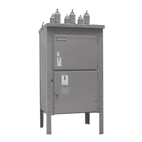
Page 5: General Description
2075-98 increased, the momentary rating and interrupting capacity Figure 1. Typical Power Circuit Breaker, Type SDV-4A. of the circuit breaker must be checked. Failure on the part of the user to receive approval of intended changes from Siemens may cause voiding the warranty. -
Page 6: Receiving, Handling & Storage
Siemens sales office. Approval must be obtained is to be eliminated or minimized. by Siemens from the carrier before any repair work can be performed. Before approval can be obtained, 1. When shipment arrives, note whether equipment is Siemens must have the documents. -
Page 7: Lifting And Moving
Receiving, Handling & Storage Heavy weight with a high center of gravity. Can cause death, serious injury or property damage. Observe all handling instructions in this instruction manual to prevent tipping or dropping of equipment. 60.0" Lifting and Moving There are a number of methods that can be used in han- dling the breaker, which when properly employed, will not damage the breaker. -
Page 8: Installation
Installation Location “X” Bracing Installation Instructions (for High Seismic The breaker should be located so that it is readily acces- Applications Only) sible for manual operation and inspection. Ample clear- Once the SDV breaker is set in place at the correct height ance should be provided for doors and panels to swing with the legs correctly installed, “X”... -
Page 9: Foundation-General Requirements
Figures 4 illustrates typi- breaker will rest must be made. A thorough analysis and cal locations for anchor bolts. No special leveling proce- careful construction may alleviate many problems at the dures are required. Figure 4. Anchoring SDV-4A Power Circuit Breaker. -
Page 10: Electrical Connections
Electrical Connections Provision for connecting to ground pads must be made in such a manner that a reliable ground connection is ob- tained. Consult latest National Electrical Code or National Hazardous voltages. Electric Safety Code for ground connection standards. Will cause death, serious injury, and Secondary Control Wiring property damage. -
Page 11: Instrument Transformers
Instrument Transformers Current Transformers Figure 5 illustrates bushing (toroidal) current transformers installed in the primary compartment of a circuit breaker. Hazardous voltage. The circuit breaker roof bushings pass through the trans- Will cause death, serious injury, and formers. Type BCM current transformers are of the toroi- property damage. -
Page 12: Installation Checks And Initial Functional Tests
Installation Checks and Initial Functional Tests Introduction Spring Discharge Check (Figure 7) This section provides a description of the inspections, checks and tests to perform on the circuit breaker prior to operation. Hazardous voltages and high-speed Inspections, Checks, And Tests Without Control Power mechanical parts. -
Page 13: Physical Inspections
Installation Checks and Initial Functional Tests Physical Inspections connected to the circuit breaker. (Refer to the specific wir- ing information and rating label for your circuit breaker to 1. Verify that the rating of the circuit breaker is compatible determine the voltage required and where the control volt- with the system. -
Page 14: Testing
Installation Checks and Initial Functional Tests 9. Incoming primary and secondary connections properly Note: No hazardous X-radiation is produced with closed made and checked for shorts or undesired grounds. contacts, or with open contacts with rated operating volt- age applied. 10. -
Page 15: Interrupter/Operator Description
Interrupter/Operator Description Introduction When the two contacts separate, an arc is initiated which Type SDV circuit breakers include three vacuum interrupt- continues conducting up to the following current zero. At ers, a stored energy operating mechanism and necessary current zero, the arc extinguishes and any conductive metal electrical controls. -
Page 16: Modes Of Operation - Discussion
Interrupter/Operator Description Figure 11. Breaker Open - Closing Springs Discharged. Figure 12. Breaker Open - Closing Springs Charged. Modes Of Operation - Discussion tion into the drive plate (13). As this plate rocks back and Some maintenance procedures are more easily understood forth, the upper pawl (24-1) (which is connected to the drive when the operating mechanism modes of operation are plate) imparts counterclockwise rotation of the ratchet... -
Page 17: Closing Mode
Interrupter/Operator Description Figure 13. Pawl and Ratchet Drive. Figure 14. Closing Mode. Closing Mode (Figure 14) - Energizing the close solenoid Opening Mode - Opening or tripping the vacuum interrupter (265) pulls the solenoid armature against the closing shaft contacts is accomplished by rotation of the trip shaft (79). actuator (75) and causes the close shaft (72) to rotate ap- Rotation may be produced either electrically, by energiz- proximately 15°. -
Page 18: Trip Free Operation
SDV-4A circuit breakers. ends of the springs. The fixed ends of these springs are... -
Page 19: Spring Charging Motor
Interrupter/Operator Description Spring Charging Motor - Figure 15 shows the spring charg- Auxiliary Switch - Figure 18 shows the breaker mounted ing motor mounted at the top of the right side of the circuit auxiliary switch. This switch provides auxiliary contacts breaker operator housing. -
Page 20: Capacitor Trip Device (Optional)
Interrupter/Operator Description 2101-98 2102-98 2100-98 Figure 19. Circuit Breaker Limit Switches. Inspection of the schematic diagrams shown in Figures 20a- 20b provides a clear picture of the logic states of the vari- ous devices for the three basic control functions. Hazardous stored voltage. - Page 21 Interrupter/Operator Description LEGEND Motor Cutoff Motor Power Disconnect Close & Trip Power Disconnect Spring Charged Trip Latch Check Closing Cutout Switch Aux Switch, Open When Bkr OPEN Motor Terminal Block Aux Switch, Closed When Bkr OPEN 01/C Control Switch Close (Remote) 52 SRC Closing, Spring Release Coil Trip 01/T...
- Page 22 Interrupter/Operator Description LEGEND Motor Cutoff Switch Motor Power Disconnect 08T Close & Trip Power Disconnect Spring Charged Switch Trip Latch Check Switch Closing Cutout Switch Aux Switch, Open When Bkr Open Motor Aux Switch, Closed When Bkr Open TPX Terminal Block CTD Capacitor Trip Device 52 SRC Closing, Spring Release Coil Trip Coil...
-
Page 23: Maintenance
• 2 Extensions (6” maximum) Regardless of the length of the maintenance and lubrica- • Torque Wrench (0-150 ft-lbs.) tion interval, Siemens recommends that circuit breakers should be inspected and exercised annually. Hex Keys Wrenches: (socket type preferred) • 3/16, 1/4 and 5/16 in. -
Page 24: De-Energize The Circuit Breaker
Should further information be desired or should particular problems arise which are not covered sufficiently for the purchaser’s purposes, the mat- ter should be referred to the local Siemens sales office. 2094-98 The use of unauthorized parts in the repair of the equipment, or tampering by unqualified personnel will result in Figure 21. -
Page 25: Checks Of The Stored Energy Operator Mechanism
Maintenance to the jack shaft by a pull rod. The dashpot is connected to the jack shaft operating shaft by a pushrod linkage. 2100-98 Figure 23. Front View of Operator Mechanism. Clean the entire stored energy operator mechanism with a dry lint-free cloth. -
Page 26: Vacuum Interrupter Stroke Check
Maintenance 1. Insert the hand charging lever into the manual charge 4. Press the Trip pushbutton after completing the contact handle socket at the front of the operator control panel. erosion check. Visually verify the Discharged condition Figure 16 shows the lever inserted. Up and down mo- of the closing springs and that the circuit breaker con- tion of the lever charges the closing springs. -
Page 27: Damper Assembly Check
Maintenance Damper Assembly Check - SDV circuit breakers contain a viscous damper assembly, shown in Figure 26, and de- scribed in some detail on page 16, and in Figure 15. While performing the manual spring charging check, a simple check of the damper mounting yoke, pin, retaining rings, and the nut for tightness should be completed. -
Page 28: Electrical Close And Trip Check - Control Power Required
Maintenance Note: A temporary source of control power and test leads may be required if the control power source has not been connected to the circuit breaker. When control power is High Potential tests employ hazardous connected to the circuit breaker, the closing springs should voltages. -
Page 29: Vacuum Integrity Test Procedure
Maintenance Vacuum Integrity Test Procedure Insulation and Contact Resistance Test Procedure 1. Observe safety precautions listed in the danger and cau- 1. Observe safety precautions listed in the danger and cau- tion advisories. Construct the proper barrier and warn- tion advisories for the Vacuum Integrity Check tests. ing light system. -
Page 30: Inspection And Cleaning Of Breaker Insulation
Inspect the painted surfaces and touch up scratches as nec- essary. ANSI-61 touchup paint is available from Siemens. • No. 1 or No. 2 denatured alcohol This paint matches the unit and is thinned and ready for •... -
Page 31: Operator Adjustments
Operator Adjustments Hazardous voltages and high-speed mechanical parts. Will cause death, serious injury or property damage. Read instruction manuals, observe safety instructions and limit use to qualified personnel. The following adjustments are not required during routine Eccentric maintenance of the breaker. These adjustments should be considered if: 1. -
Page 32: Spring Release Latch "Bite" Adjustment
Operator Adjustments Spring Release Latch “Bite” Adjustment self clinching nut 14 full turns. The set screw will be within 1 to 2 turns of being flush 1. Remove front panel of operator. to the self clinching nut, protruding slightly. 2. Find spring release latch adjusting screw located in the The adjusting screw should not be advanced more than vertical flange of the operator (10-32 recessed hex socket set screw, see Figure 27). -
Page 33: Overhaul
Closing Springs. Closing Operations Breaker Type 5,000 SDV-4A Replacement Of Closing Springs - Figure 29 shows the use of a 3/4 inch socket wrench to relieve spring tension on the Replacement At Overhaul - The following components are closing springs. The bottom of the breaker operator frame replaced during an overhaul of the circuit breaker, when has openings providing access to the tensioning bolts. -
Page 34: Replacement Of Opening Spring
Overhaul Replacement Of Opening Spring - The opening spring may Replacement Of Closing and Tripping Solenoids (Devices be removed and replaced without the need to use a spring 52SRC and 52T) - Replacement of either the closing or trip- keeper or compression aid. ping solenoids is straightforward. -
Page 35: Replacement Of Motor Cutoff Switch (Device Ls1) And Spring Charged Switch (Ls2)
Overhaul Replacement of Motor Cutoff Switch (Device LS1) and Wires to the switch must be marked and removed. The Spring Charged Switch (LS2) - The motor cutoff switch stop plate and switch may then be removed as a subas- (LS1) and spring charged switch (LS2) form a common as- sembly. -
Page 36: Replacement Of Damper Assembly
Overhaul Replacement of Enindine Damper Assembly (see Figure Replacement of Liner Decelerator (shock absorber) (see Figure 26) - For replacement of this type of shoch absorber, 26) - Damper replacement will require the removal of a pin refer to Figure 35b and implement the following steps: which ties the damper mounting yoke to the circuit breaker Loosen the jam nut on the body of the shock absorber and operator frame. -
Page 37: Preparation
Overhaul Open End or Box End Wrenches: 4. Remove the two snap rings from either end of the pins • 5/16, 3/8, 7/16, 1/2, 9/16, 5/8, 11/16, 3/4, and 7/8 in. of the pivot block. With a large flat bladed screwdriver, pry the lever arms from the pivot block. - Page 38 Overhaul 12. Position the interrupter with the slot in the moving ter- shown in Table 7. When properly installed, the rod end minal uppermost and slide the moving terminal through bearing will be in a vertical position. the plastic support ring on the large polehead. Move the stationary end of the interrupter (with copper spacer 20.
- Page 39 Overhaul Table 7: Critical Fasteners and Torque Limits Stationary Contact Movable Contact Interrupter Clamp Interrupter Family Size Torque Size Torque Size Torque 45-50 ft-lbs. 15-20 ft-lbs. 26-35 ft-lbs. VS17006 61-68 N-m 20-27 N-m 35-47 N-m 60-65 ft-lbs. 15-20 ft-lbs. 26-35 ft-lbs. VS25008 81-88 N-m 20-27 N-m...
- Page 40 Overhaul Figure 38. VS25008 15.5kV, 2000 Amp, & 25.8/27.6 kV, 2000Amp. Figure 39. VS25008 25.8/27.6kV, 1200 Amp. Figure 40. Tube Clamp Fastening Procedure / Stroke Adjustment.
-
Page 41: Periodic Maintenance And Lubrication Tasks
Overhaul Periodic Maintenance and Lubrication Tasks Sub-Assembly Inspect For Item Primary Power Path Vacuum Interrupter 1. Cleanliness 2. Contact erosion Note: Perform with Manual Spring Checks 3. Vacuum integrity Note: Perform with High Potential Tests Interrupter Operator Cleanliness 1. Dirt or foreign material Mechanism Fasteners 1. -
Page 42: Troubleshooting
Overhaul Troubleshooting Problem Possible Causes and Remedies Symptoms Breaker fails to close Closing springs will not automati- 1. Secondary control circuit is cally charge. de-energized or control circuit fuses are blown. Check and energize or replace if necessary. 2. Damage to wiring, terminals or connectors. - Page 43 Overhaul Troubleshooting (continued) Possible Causes and Remedies Problem Symptoms Nuisance or false close Electrical problem 1. Nuisance or false closing signal to TB4. Check relay logic. Correct as required. 2. Closing coil (52SRC) terminal 2 is shorted to ground. Check to determine if problem is in wiring or coil.
-
Page 44: Ordering Replacement Parts
This information should include: correct for the breaker in question. Without this serial num- ber, Siemens cannot be sure of the correct identity of the 1. Breaker serial number. (On breaker nameplate.) desired parts. -
Page 45: Appendix
Appendix Table A-1 Type SDV Ratings Type Definition: SDV-4A (Generic for SDV4), followed by Rated Maximum Voltage (kV), followed by Rated Short Circuit Current (kA) Ratings Rated Rated Rated Rated Rated Transient Rated Rated Rated Maximum Voltage Continuous Short- Recovery Voltage... - Page 46 Rated Duty Cycle — CO-15 sec-CO CO-15 sec-CO O-0.35-CO-15 sec-CO O-0.3sec-15sec-CO Seismic Withstand Standard - SDV-4A (IEEE STD 693-1997) Moderate (0.25) Moderate (0.25) Optional - SDV-4A (IEEE STD 693-1997) High (0.50) High (0.50) 1 Breaker in closed position only. 2 Requires “X” bracing on circuit breaker legs.
- Page 47 Siemens Power Transmission & Distribution Inc. P.O. Box 29503 Raleigh, NC 27626-0503 SGIM-3788F (Replaces SGIM-3788D) (2-03) Printed in U.S.A. © 2002 Siemens Power Transmission & Distribution Inc. SIEMENS is a registered trademark of Siemens AG.