
Related Manuals for Siemens Fusesaver


Summary of Contents for Siemens Fusesaver
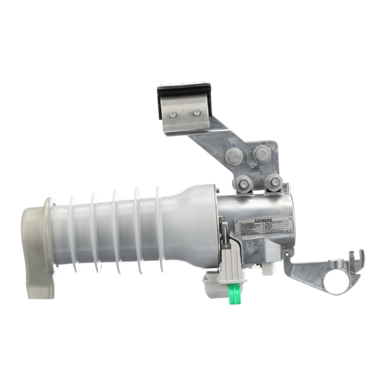
- Page 1 Fusesaver® Medium-voltage circuit breaker installation and operation manual usa.siemens.com/fusesaver...
-
Page 2: Table Of Contents
5.2 Manual operation 6.2 Battery replacement Electrical isolation 6.3 Battery charging External lever Fusesaver replacement Fault passage indication 6.5 Return an item Fusesaver event data Spare parts Manufacturer’s product liability 6.8 Fusesaver disposal Battery disposal Fusesaver | Installation and operation manual... -
Page 3: Safety Information
• Is trained in rendering first aid. exposed live parts. Only qualified personnel who are familiar with this equipment should install or operate it. Fusesaver | Installation and operation manual... -
Page 4: Signal Words
When additional information is required to address any particular problem not adequately explained in this manual, please contact your local Siemens Service Center for further advice. Fusesaver | Installation and operation manual... - Page 5 2 Packing and storage 2.1 Packaging Typical Weights and Dimensions: Each Fusesaver or Fusesaver kit is To open the box, use a box cutter to Package of line-mounted Package of cross arm/pole-mounted packaged in a cardboard box labeled cut through the sealing tape and then...
-
Page 6: Receipt And Handling
Store in a clean and dry location. • Major damage must be documented photographically. Do not drop the Fusesaver or any of its parts or accessories. Fusesaver | Installation and operation manual... -
Page 7: Resistance Of Main Circuit
3 Workshop testing Every Fusesaver is inspected and tested at the factory before dispatch. No further testing The vacuum interrupter may emit x-rays during by the end user is required. However, if the dielectric testing. user has a policy to do confirmation testing X-rays may be hazardous to your health. - Page 8 This blink pattern repeats three times. For example, the blink pattern for a battery with a “low” charge is: xx – 1s – xx – 1s – xx where “x” is a blink. Refer to section 6.2 for how to recharge batteries. Fusesaver | Installation and operation manual...
- Page 9 3.4 Operations test Fusesaver operation The user can conduct an operations test to confirm the Fusesaver can trip and close. Connect the communications module to the Fusesaver and wait until the LED blinks to confirm connection to the Fusesaver. To open the Fusesaver press the GREEN actuating button.
-
Page 10: Connecting Cables
The preferred method for connecting to the Fusesaver is with a cable that has a For mounting options not covered here it has an insulating sleeve between two-hole NEMA palm crimped to one end. - Page 11 4 Installation procedure Line-mounted Fusesaver The Fusesaver assembly can now be installed to the line according to the following steps: Clamping to dead-end Prepare the Fusesaver on the ground prior to installation by fitting the line clamp, connecting cables and birdguard as follows: Fusesaver ready for installation A.
- Page 12 Fusesaver will damage the product. The maximum cantilever load is 110 lbs (50 kg). Prepare the Fusesaver on the ground prior to installation by fitting the line clamp, Do not pull on the Fusesaver. connecting cables and birdguard as follows:...
- Page 13 Uncoil and then secure the other B. Fishplate connection (II) connection cable at the crossarm (optional): Attach the crossarm side of the Fusesaver to the partner bracket with post insulator on fuse or isolating link assembly. Fishplate connection the crossarm with the fish plate Fit the wildlife guard over the first using included 1/2"...
-
Page 14: Communications Module
4.2.3 Pole mount installation Primary cell attachment tool module attachment/fitting The Fusesaver can also mount directly on the pole using a variation of the crossarm mounting solution. The bracket on the earth end of the composite post insulator The communications module has is designed for pole mounting. -
Page 15: Fusesaver Status Check
4 Installation procedure 4.4 Fusesaver configuration To install a communications module to a Fusesaver in service follow these steps: To remove a communications module from a Fusesaver in service, follow The Fusesavers can be configured either Fitting communications module When a communications module... -
Page 16: Operation
When in the closed state the lever on the Fusesaver subject to the module operates all the Fusesavers on Fusesaver operates automatically configuration setting. Cancellation only... -
Page 17: Electrical Isolation
5 Operation 5.3 Electrical isolation 5.4 External lever The Fusesaver can be used to open the visible air gap for the applicable The external lever is used by an External lever operation the circuit and de-energize the line after system voltage;... -
Page 18: Fault Passage Indication
ON-OFF pattern until the user can check the operation either the configured time-out occurs or status of the Fusesaver, view last fault the local operator closes the Fusesaver. data and download the event log. If the Fusesaver has tripped to lockout, then the LED is powered by the communications module battery. -
Page 19: Maintenance
10-year life subject to appropriate site selection. Sites with inadequate line current to power the During firmware updates the Fusesaver protection is deactivated. Fusesaver or that have a high number of Ensure upstream protective devices are available to provide back-up faults may deplete the battery sooner. -
Page 20: Battery Charging
18650 lithium-ion cells. communications module taking A. Remove the battery cells from care to get the polarity correct. • Siemens does not approve the use of the rechargeable communications alternative battery types. D. Fit the cover and tighten the screws module. -
Page 21: Fusesaver Replacement
C. Wirelessly connect to the remaining from a multi-phase installation is Fusesaver’s in the line using the Typically a Fusesaver would only need replacement if it has exceeded its electrical required, the user should follow these “Change an existing installation” tab life or has had an internal failure. -
Page 22: Return An Item
6.8 Fusesaver disposal The Fusesaver consists of the • Rubber materials following materials: • Ceramics If a Fusesaver is faulty, please contact The materials of the Fusesaver are • Steel your local Siemens Service Center to recyclable. Disposal of the Fusesaver •... - Page 23 7 Troubleshooting Refer to the FAQ page on the Siemens Outdoor Systems Data Management Cloud site at https://sosdmc.siemens.cloud/ for the latest troubleshooting guide. User access authentication required. Fusesaver | Installation and operation manual...
- Page 24 • Batteries: Should be recycled via a recycling company. Disassembly may cause an unbalanced load, and could result in falling objects. Take appropriate precautions in a properly designated workspace to maximize support and stability. Fusesaver | Installation and operation manual...
- Page 25 Siemens does not make representations, warranties, or assurances as to the accuracy or completeness of the content contained herein. Siemens reserves the right to modify the technology and product specifications in its sole discretion without advance notice.