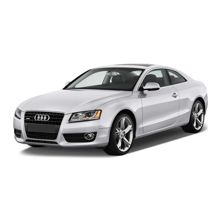
Audi A5 Service Training
Networking
Hide thumbs
Also See for A5:
- Owner's manual (313 pages) ,
- Pricing and specification manual (58 pages) ,
- Service training (56 pages)
Table of Contents
Advertisement
Quick Links
Advertisement
Table of Contents

Summary of Contents for Audi A5
- Page 1 Service Training Audi A5 - Networking Self-Study Programme 395...
- Page 2 Innovations in the electrical system and electronics on the Audi A5 The number of control units in motor vehicles con- tinues to increase, and the Audi A5 is no exception. Many functions would not be possible without this multiplicity of control units. Ongoing advance pro- fessional training is needed in order to abreast with the rapid rate of development within this sector.
-
Page 3: Table Of Contents
Contents Overview Fuses and relays ............4 Installation locations of Infotainment components . -
Page 4: Fuses And Relays
Overview Fuses and relays Relay carrier and fuse panel in luggage compartment on right Fuse panel in dash panel on right and CAN node connectors Fuse panel and external starter connec- tion in plenum chamber Relay carrier and fuse panel in electronics box Connector station and CAN node connector on left A-post... - Page 5 Fuse panel and battery disconnecting element at battery positive pole Relay carrier and mounting bracket for onboard power supply control unit in driver-side footwell Fuse panel in dash panel on left 395_015...
-
Page 6: Installation Locations Of Infotainment Components
Overview Installation locations of Infotainment components Connection for external Telephone transmitter and receiver unit Information control unit, audio sources R199 (MOST) front (MOST) Radio (CAN) CD changer (MOST) - Page 7 Navigation (MOST) Amplifier (not with chorus) Radio (MOST) Digital satellite radio (USA) DAB tuner (MOST) TV tuner 395_001...
-
Page 8: Installation Locations Of Control Units On The Powertrain Can Bus And Extended Can Bus
Overview Installation locations of control units on the powertrain CAN bus and extended CAN bus Headlight range control, control unit Data bus diagnostic interface Automatic gearbox control unit Adaptive cruise control unit Engine control unit Airbag control unit Control units on the powertrain CAN bus Control units on the extended CAN bus... - Page 9 Lane change assistant control unit (master) ECD control unit (electroni- cally controlled damping) Lane change assistant control unit (slave) 395_002...
- Page 10 Overview Installation locations of control units on the dash panel insert / suspension CAN bus Auxiliary heater control unit Data bus diag- nostic interface ABS/ESP control unit Dash panel insert control unit Steering angle sensor Control units on the dash panel insert/suspension CAN bus...
- Page 11 Parking brake and hand- brake control unit Park assist control unit 395_003...
-
Page 12: Installation Locations Of Control Units On The Convenience Can Bus
Overview Installation locations of control units on the convenience CAN bus Door control unit Tyre pressure monitor- ing system control unit (USA only) Data bus diagnostic interface Climatronic control unit Seat control units Steering column electronics control unit Onboard power supply control unit Door control unit Control units on the convenience CAN bus... - Page 13 Trailer detector Rear-view camera system control unit control unit Convenience system central control unit Control unit for special vehicles 395_004...
-
Page 14: Networking / Vehicles With Infotainment Can Bus
Overview Networking / vehicles with infotainment CAN bus Rear-view camera system J772 Air quality sensor G238 Trailer detector control unit Refrigerant pres- J345 sure/temperature sender G395 Multi-function Steering column steering wheel electronics con- Garage door opera- control unit trol unit tion control unit J527 J453... - Page 15 Powertrain CAN bus Infotainment CAN bus Convenience CAN bus Diagnostics CAN bus Dash panel insert/suspension CAN bus LIN bus Extended CAN bus Subbus systems Control unit with display in dash panel insert J285 Steering angle sender G85 Park assist control unit J791 Electric park and handbrake control...
- Page 16 Overview Networking / vehicles with MOST bus Rear-view camera system Air quality sensor J772 G238 Trailer detector control unit Refrigerant pres- J345 sure/temperature sender G395 Steering column Multi-function electronics con- steering wheel Garage door opera- trol unit control unit tion control unit J527 J453 J530...
- Page 17 Powertrain CAN bus Convenience CAN bus Dash panel insert/suspension CAN bus Extended CAN bus Diagnostics CAN bus Control unit with display in dash LIN bus panel insert J285 Subbus systems Steering angle sender G85 Most bus Park assist control unit J791 Electric park and handbrake control...
- Page 18 Overview CAN node connectors Installation location The CAN node connectors are located on the relay carrier on the left and on the fuse holder in the dash panel on the right. Relay carrier, left Fuse holder in dash panel on right 395_007 395_008 Assignments...
- Page 19 Diagnostics To perform diagnostics on the Audi A5, the VAS test- ers require the basic CD 11.XX and the relevant branded CD by Audi. This is because the data protocol (language) which several control units and the VAS tester use to inter- change data has changed.
- Page 20 395_031 Introduction The new Audi A5 has an independent data bus diagnostic interface J533. The diagnostic interface represents the link between the various CAN bus systems. Depending on specification, the vehicle has between 4 and 6 different onboard CAN bus systems: •...


Need help?
Do you have a question about the A5 and is the answer not in the manual?
Questions and answers