Advertisement
Quick Links
USA
SERVICE OFFICE
Dometic Corporation
509 South Poplar Street
Lagrange, IN 46761
260-463-4858
CANADA
Dometic Distribution
866 Langs Drive
Cambridge, Ontario
CANADA N3H 2N7
519-653-4390
For Service Center
Assistance Call:
800-544-4881
SERVICE INSTRUCTIONS
Form No. 3308740.004 11/03
©2003 Dometic Corporation
LaGrange, IN 46761
3308741.002 2-Way
3308742.000 3-Way
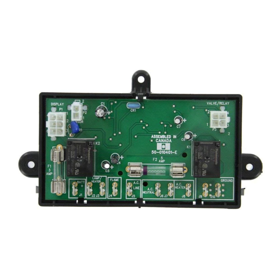
Universal Power Module Kit
Installation Instructions
3308741.002 2-Way Kit Includes:
(1) 3850415013 Power Module Assembly
(1) 3308727.001 Wiring Diagram
(1) 3308770.001 Wire, Black
(1) 3308772.007 Wire Harness, 2-way
(1) 3308774.003 Screw, #4 x 1/2"
PRH Self Tapping
(1) 3308740.004 Installation Instructions
3308742.000 3-Way Kit Includes:
(1) 3850415013 Power Module Assembly
(1) 3308727.001 Wiring Diagram
(1) 3308769.003 Wire Connector
(1) 3308770.001 Wire, Black
(1) 3308771.009 Wire, Red
(1) 3308773.005 Wire Harness, 3-Way
(1) 3308774.003 Screw, #4 x 1/2"
PRH Self Tapping
(1) 2930385006 Relay, 12VDC
(1) 3308740.004 Installation Instructions
AMES/AES 2-Way
AMES/AES 3-Way
1
Americana
Advertisement

Related Manuals for Dometic 3308741.002


Summary of Contents for Dometic 3308741.002
- Page 1 509 South Poplar Street Installation Instructions Lagrange, IN 46761 260-463-4858 CANADA Dometic Distribution 3308741.002 2-Way Kit Includes: 3308742.000 3-Way Kit Includes: 866 Langs Drive (1) 3850415013 Power Module Assembly (1) 3850415013 Power Module Assembly Cambridge, Ontario (1) 3308727.001 Wiring Diagram (1) 3308727.001 Wiring Diagram...
-
Page 2: Safety Instructions
J4; if not wired correctly damage to the board will result. These instructions must be read and under- stood before installation of this kit. This kit must be installed by a Dometic Service Cen- ter or a qualified service technician. Modifi- cation of this product can be extremely haz- ardous and could result in personal injury or property damage. - Page 3 14. Connect P1, P2, and P3 connectors to the appro- FIG. 2 priate terminals on circuit board. 15. Snap cover into place carefully so as to avoid pinch- SCOTCHLOK 562 U-Contact ing any wiring. Secure cover to backplate with #4 x 1/2"...
-
Page 4: Wiring Diagram
WIRING DIAGRAM 3308727.001 CIRCUIT BOARD POWER MODULE CIRCUIT BOARD DISPLAY THERMISTOR 120V AC 12V DC GAS VALVE REIGNITER THERMOCOUPLE ELECTRODE RETAINER FOR BURNER BLUE BLACK BLUE TERMINAL BLOCK BROWN WHITE GROUND TERMINAL STRIP YELLOW ORANGE ABSORPTION UNIT GREEN HEATER 120V AC HEATER 12V DC LIGHT SWITCH... - Page 5 This manual has been provided courtesy of My RV Works, Inc. www.myrvworks.com You can find more RV service manuals here: www.myrvworks.com/manuals Over the years of running a mobile RV repair service, having a dedicated place to access service manuals for all the different appliances and components found on RVs was something that I always had a desire to create.