Table of Contents
Advertisement
Advertisement
Table of Contents

Subscribe to Our Youtube Channel
Related Manuals for Smart Optics Activity 850


Summary of Contents for Smart Optics Activity 850
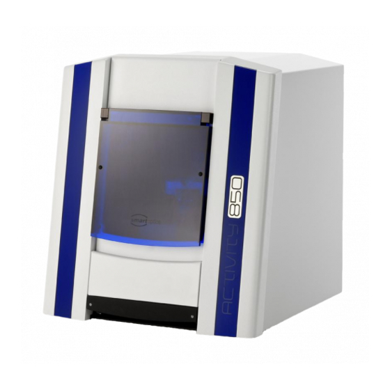
- Page 1 Operating Manual A product of smart optics Sensortechnik GmbH...
-
Page 2: Table Of Contents
Table of contents Table of contents TABLE OF CONTENTS LIST OF FIGURES ICONS GENERAL SAFETY INFORMATION TECHNICAL SPECIFICATIONS CE DECLARATION OF CONFORMITY GENERAL SAFETY INFORMATION INSTALLATION 8.1 S ELECTING THE INSTALLATION LOCATION 8.2 U NPACKING AND SCOPE OF DELIVERY 8.3 C ARRYING POINTS 8.4 R EMOVING THE SCANNER FROM THE PACKAGING... - Page 3 Table of contents SCANNING PROCEDURE 12.1 C LAMPING THE MODEL 12.2 C REATING A PRESCAN 12.3 C ASE STUDY BRIDGE WITH SQUEEZE BITE 12.4 C ASE STUDY COMPLETE JAW SCAN 12.5 C ASE STUDY OCCLUSION SCAN SYMBOLS 13.1 T HE SYMBOLS 13.2 T VIEWER SYMBOLS OBJECT VIEW...
-
Page 4: List Of Figures
List of figures 2. List of figures 1: S IGURE CANNER SIDE VIEW ............................12 2: S IGURE CANNER HOLDING POINT ........................... 12 3: S IGURE CANNER HOLDING POINT ........................... 12 4: M IGURE AINS SWITCH ON THE REAR OF THE DEVICE ...................... - Page 5 List of figures 48: S IGURE QUEEZE BITE ALIGNMENT PRESCAN ......................... 42 49: C IGURE UT BITE REGISTRATION ............................ 43 50: C IGURE UT BITE REGISTRATION ............................ 43 51: C IGURE OMPLETE JAW SCAN ..........................44 52: C IGURE OMPLETE JAW ALIGNMENT PRESCAN ......................
-
Page 6: Icons
Useful hints are marked with a light bulb in the operating manual 4. General safety information Proper use: The Activity 850 scanner is intended for use in performing optical, three-dimensional measurements of human jaw models. It is possible to measure articulated models in order to simulate masticatory movements using corresponding software, as in an articulator. -
Page 7: Technical Specifications
Technical specifications 5. Technical specifications Dimensions 440 mm x 480 mm x 430 mm (WxHxD) Weight 23 kg Connection voltage 100-240 V AC, 50-60 Hz Power consumption 60 W Protection class IP11 Permissible temperature 18-30 °C range Measureable objects Plaster models of teeth Minimum clamping range 40 mm of the removable object... -
Page 8: Ce Declaration Of Conformity
EU Directive. If the device is modified without our agreement, this declaration ceases to be valid. Device designation: Optical 3D scanner Device type: Activity 850 Relevant EU Directives: Machinery Directive (98/37/EC) Low Voltage Directive (73/23/EEC) EMC Directive (93/68/EEC) -
Page 9: General Safety Information
The "Activity 850" scanner has been developed and manufactured in accordance with the applicable safety standards and with the greatest possible care. In spite of this, the risk of an electric shock, overheating or fire due to technical defects in individual components cannot be totally excluded. - Page 10 General safety information continuing to operate when the flap is opened. As there is a theoretical possibility of the protection mechanism failing, this entails a residual risk which you can counter by complying with the following rules of use: 7.1. Do not open the front flap during a scanning procedure until after a corresponding prompt or the end of a scanning procedure has been displayed on the screen.
-
Page 11: Installation
Installation 8. Installation 8.1 Selecting the installation location Before installing the scanner, you should select a suitable installation location. A suitable, stable base (bench, tabletop etc.) should be chosen as an installation location. If you install the computer required for operating the scanner underneath the worktop, the available worktop area should be at least 1.1 m x 0.75 m (front width x depth). -
Page 12: Carrying Points
Installation Scope of delivery: - 1 scanner - 1 power cord - 2 USB cables - 1 hex key - 1 user manual - 1 calibration object - 1 software installation CD including calibration data - 1 removable object holder - 1 measuring range template 8.3 Carrying points Carrying points are provided to move the device. -
Page 13: Removing The Scanner From The Packaging
Installation 8.4 Removing the scanner from the packaging To remove the scanner from the packaging, one person stands to the left of the scanner and the other person stands to the right. Each person must take hold of the scanner with one hand on the upper support point. Next, tilt the scanner slightly to the rear until you can grip underneath the scanner at the front with your other hand. -
Page 14: Installation
Installation 9. Installation 9.1 Installing the scanner Please make sure that the mains switch is at the "0" position before installation. (The position of the main switch maybe different) Figure 4: Mains switch on the rear of the device Connect the device to the USB cables using the USB ports on the rear of the device. Fuse USB camera USB device control... -
Page 15: Installing The Computer
Installation Connect the other ends of the USB cables to USB connections on the rear of your computer. Connect the scanner to a power source via the mains connection on the rear. Now switch the scanner on at the mains switch. Now first switch the scanner off again and continue by installing the computer and operating software. -
Page 16: Figure 6: Language Selection
Installation Now select the required language (Fig. 6) and confirm your selection with the "Next" icon (Fig. 7). Figure 6: Language selection Figure 7: Setup Wizard Define the installation location for the software by using the "Browse" button to define the path. The installation program suggests a standardized path that you can use. -
Page 17: Figure 8: Select Installation Location
Installation Figure 8: Select installation location Define the software name in the "Select Destination Location Folder" window. Then click on "Next". Figure 9: Start Menu Select whether you require a Desktop symbol and confirm with "Next". -
Page 18: Figure 10: Creating A Desktop Symbol
Installation Figure 10: Creating a Desktop symbol Before starting the installation, check your selected settings and chose "Next". The installation starts immediately (Fig. 11). Figure 11: Installation... -
Page 19: Figure 12: Installation
Installation Figure 12: Installation Confirm the installation of the driver with "Next". Then complete the installation with "Finish". The drivers are now installed and the process is completed. Figure 13: Completing the installation... -
Page 20: Importing Calibration Data
Installation 9.4 Importing calibration data The scanner–specific calibration data must be imported during the initial installation. Start the Activity software via the Desktop icon or from the Start Menu. This is followed by a software message (Calibration directory not found). Click "OK" to start the "Installer Tool". -
Page 21: Figure 16: Selected Folder
Installation Click "Next". The calibration data is imported into the Activity software. Figure 16: Selected folder The scanner installation has been completed; you can close the installer with "OK" and restart the scanner software. Figure 17: Implementing the sensor data... -
Page 22: Calibration Procedure
Calibration procedure 10. Calibration procedure 10.1 Axis calibration Start the scan software by clicking on the Activity icon located on your Desktop. Place the spacer plate in the scanner. Clamp the calibration model on the removable object holder and place it in the scanner (Fig. 18). Object base Spacer plate Figure 18: Calibration model with spacer plate... -
Page 23: Calibration
Calibration procedure The scanner now performs an automatic axis calibration. The following message will appear after the axis calibration is complete: Figure 20: Scan software calibration If the axis calibration fails, please check the height alignment of the model in the measuring field. -
Page 24: Figure 22: Calibration Model Registration
Calibration procedure Start this procedure as follows: A window opens under Options Service Calibration object registration (Fig. 22). Figure 22: Calibration model registration Individual values are indicated on the rear of the calibration model. Please enter these in fields #1 and #2. -
Page 25: Basic Information About The Device
11. Basic information about the device 11.1 Functioning of the Activity 850 The optical scanner with the designation "Activity 850" is used for the three-dimensional measuring of jaw models, in orthodontic and prosthetic applications. The most important components of the scanner are the 3D sensor and the positioning unit with object holder. - Page 26 Basic information about the device Individual measurements: After completing the scan definition, the software automatically calculates a scan program for recording the positions specified by the operator and starts these. The positions provided in the scan program are started up by the positioning unit and a 3D measurement is performed. When scanning adjacent tooth stumps, it is usually necessary to measure the stumps in isolation without the adjacent stumps, as otherwise the interdental area cannot be captured by the 3D sensor.
-
Page 27: Figure 24: Device Front
Basic information about the device The most important components and operating controls of the scanner are explained below. Lid/Case opening Device designation System drawer Figure 24: Device front Systemauszug USB port for the motor and scanner control USB port for the camera Fuse Power cord connection Figure 25: Device rear... -
Page 28: Figure 26: Side View
Basic information about the device System drawer Figure 26: Side view Figure 27: System drawer... -
Page 29: Figure 28: Data Plate
Basic information about the device Device serial number CE mark 3D sensor number Figure 28: Data plate Use only the USB cables included in the scope of delivery, if possible. These have undergone multiple testing at our company in conjunction with your scanner. Communication problems can result between the scanner and PC if cable lengths over 2 metres are used. -
Page 30: Interior
Basic information about the device 11.2 Interior Lid/Case opening 3D sensor (not visible from outside) Object base/ Model holder Rotating- swiveling unit Mains switch Figure 29: Rotating-swivelling unit Main/ Swivelling axis Rotating- swiveling unit Base holder Figure 30: Rocker/Rotating-swivelling unit... -
Page 31: Object Holder
The interior lighting switches off automatically when the flap is closed. 11.3 Object holder Individual parts of the object holder The scope of delivery for the object holder of the Activity 850 consists of the following components: Figure 31: Individual parts of the object holder... -
Page 32: Figure 32: Object Holder System
This clamp is fastened or released using the hex key (4). Using the object holder system: The object holder of the Activity 850 primarily comprises a system base plate fixed on a rotating- swivelling unit. -
Page 33: Positioning The Model On The Object Holder
Basic information about the device Example: Standard model holder without spacer plate Figure 33: Object holder system with model 11.4 Positioning the model on the object holder Positioning: The correct positioning of the model on the object holder is indispensible for correct measuring results. -
Page 34: Figure 34: Height Alignment
Basic information about the device Figure 34: Height alignment The height alignment can be checked using the measuring range template. To do this, place the template on the rotating and swivelling unit and check the height in the cross hairs with the jaw model. -
Page 35: Scanning Procedure
Scanning procedure 12. Scanning procedure 12.1 Clamping the model Clamp the model in the removable object holder and align the height using the spacer plate (see Figure 33). 12.2 Creating a prescan Depending on the scanner and CAD software combination, it is not necessary to fill out the project information thanks to a special interface, as this is automatically undertaken by the CAD software (e.g. -
Page 36: Figure 36: "New Measurement
Scanning procedure Figure 36: "New measurement" After providing a name for the measurement, confirm this with "OK". The scanner then begins with a preview image. After a few seconds, a 2D scan will appear on the viewer, and you can select your individual scan type. During the prescan or the 3D scan, the symbol is displayed, and you can use this to cancel the corresponding scanning process. -
Page 37: Case Study : Bridge With Squeeze Bite
Scanning procedure Use the spacer plate to ensure the correct height alignment in the scanner. (see Figures 33 and 34). A tooth diagram of the jaw to be scanned is located at the upper left. Activate the "Jaw type" checkbox to select whether an upper or lower jaw is involved. Indicate under "Scan type"... -
Page 38: Figure 38: Starting The Scan Process
Scanning procedure After aligning all scan positions, start the 3D scan with this icon. Figure 38: Starting the scan process The scanner now moves the model down automatically, based on the predefined scan strategy, and compiles a number of individual measurements from various perspectives. In the case of adjacent teeth, it is necessary to additionally measure the individual teeth independently, as otherwise the interdental area cannot be recorded with sufficient accuracy. -
Page 39: Figure 40: Data Set Before "Matching
Scanning procedure Remove all teeth from the saw-cut model, apart from the one required. Close the front flap and click "Continue" or "Continue with axis homing". If "Continue with axis homing" is selected, a new reference travel of the axes, object holder or all axes is first executed before the measurement is continued, after removing the stumps. -
Page 40: Figure 41: "Rescan" Mode
Scanning procedure If "Rescan Mode" is enabled, this green cross will be shown in the centre of the 3D viewer (see above). Now the edge of the data hole must be positioned below the cross using the familiar mouse options (left mouse button rotate, right mouse button move and scroll wheel zoom). If the centre of a hole is positioned directly below the cross, the scanner will move to an incorrect rescan position and possibly a recording at another point. -
Page 41: Figure 43: Save Project
Scanning procedure If you click on the blue start button, any number of rescans can now be performed until all desired areas are recorded. For details, such as in interdental spaces, please remove all teeth that impair the sensor's view of the area to be closed, e.g. directly adjacent teeth and segments that are not required for the scan. -
Page 42: Figure 44: "Matching" Process
Scanning procedure After completing the scan and cutting the data set to size, you need to perform a matching. To do this, click on the following icon: Figure 44: "Matching" process The recorded individual measurements are automatically added together by special algorithms, and an STL is created. -
Page 43: Figure 46: "Bite Registration" Symbol
Scanning procedure Figure 46: “bite registration" symbol You are then prompted to position the bite registration and give the measurement a name. Once you have given the measurement a name and confirmed with "OK", a new information window will appear. Figure 47: Information window Confirm with "Yes", and the device will immediately commence with the 3D scan based on the selection created in the main scan (see Fig. -
Page 44: Figure 49: Cut Bite Registration
Scanning procedure Figure 49: Cut bite registration After completing the 3D scan, you can evaluate the result and, if necessary, perform rescans, or cut to size with the cutting tool described above. Save the change and start the matching process. The matching button for a bite registration scan is not enabled unless the model data set has been matched previously. -
Page 45: Case Study: Complete Jaw Scan
Scanning procedure 12.4 Case study: complete jaw scan Clamp the model on the removable object holder. Ensure the height alignment in the measuring range. (See Fig. 34). For certain applications, e.g. archiving in orthodontics, it is necessary to simply and quickly scan a complete jaw. -
Page 46: Figure 52: Complete Jaw Alignment Prescan
Scanning procedure A new control (blue line) is shown in the prescan view: shift move Figure 52: Complete jaw alignment prescan The scan range is adapted to the size of the object to be scanned using the yellow checkpoints. The jaw must be inside the blue outline, the scan range. Start the 3D scan. -
Page 47: Figure 54: Complete Jaw 3D Scan
Scanning procedure Figure 54: Complete jaw 3D scan After the 3D scan, cut the data set if necessary. Now start the STL calculation with the Matching button. The matching process for a complete jaw can take up to several minutes, irrespective of the number and size of the scans to be matched or the selected thinning level and computer capacity. -
Page 48: Case Study: Occlusion Scan
Scanning procedure You can tell from the colouring of the file tab whether a data set is already "matched", i.e. whether there is an STL. (Blue - individual records, Yellow - STL data set, Grey - 2D scan) (see Fig. 57) Figure 56: Tabs 12.5 Case study: occlusion scan You can also scan a jaw pair in occlusion. -
Page 49: Figure 57: Fixed Jaw
Scanning procedure As soon as you have scanned in the lower and uppers jaw, you must perform a "vestibular scan", which allows the software to calculate how the jaw halves are located relative to one another. The scanned jaws do not have to be matched, as all scans performed are added together at the end of the process. -
Page 50: Figure 59: New Measurement
Scanning procedure Figure 59: New measurement Once the prescan has been performed, click on "Antagonist Alignment" in the left of the project entry screen, after which you can select what method is to be used to perform the vestibular scan. Figure 60: Antagonist Alignment NOARTICULATOR: This procedure allows you to align both jaws to a bite (with non-articulated jaw models) as long... -
Page 51: Figure 61: Prescan
Scanning procedure Figure 61: Prescan Start the scanning process as usual. The outer sides (vestibular view) are scanned by the device, as shown below: Figure 62: Vestibular scan Click on the articulation icon: Figure 63: "Articulation" icon The software now indicates in succession which jaw has to be loaded. First confirm the "Lower jaw tab"... -
Page 52: Figure 64: Select Lower Jaw Figure 65: Select Upper Jaw
Scanning procedure Figure 64: Select lower jaw Figure 65: Select upper jaw The alignment for the "NOARTICULATOR" must always be performed with the 3-point method. To obtain a complete, mutually aligned STL data set from both jaw halves, the individual scans must be added together. You have to indicate reference points on the scans for this. -
Page 53: Figure 66: Lower Jaw Alignment
Scanning procedure Figure 66: Lower jaw alignment Once you have selected the reference points of the lower jaw to your satisfaction, click on the "Next" icon in the viewer to load the upper jaw. Figure 67: "Next" Follow the same procedure as with the lower jaw and select the "Next" icon again once you are satisfied with the selection. -
Page 54: Figure 69: Aligned Upper And Lower Jaws
Scanning procedure Figure 69: Aligned upper and lower jaws You can detect an offset more easily using differing colour schemes for the upper and lower jaw. If you are pleased with the data set, confirm with the "Next" button, after which the software will automatically commence the matching process. -
Page 55: Symbols
Symbols 13. Symbols 13.1 The symbols Activity icon Perform 3D scan Perform 2D scan Move automatically to the service position Open a new project Open an existing project or STL file Start the matching process Add a new measurement Add bite registration Add wax-up Continue in workflow... - Page 56 Symbols Cut data inside the selection Cut data outside the selection Undo the last cutting action or measurement Open the dialog "Fill holes" Save the last work step (possible if activated blue) Open "Settings" dialog Information on the product End the Activity program...
-
Page 57: The 3D Viewer Symbols (Object View)
Symbols 13.2 The 3D viewer symbols (object view) Show camera angle Show front view Show rear view Show left side Show right side Show upper side Show lower side Show data set in isometric alignment Rotate the object around the X axis only Rotate the object around the Y axis only Rotate the object around the Z axis only Normal rotation mode... -
Page 58: Activity Menu Options
Symbols 13.3 Activity Menu options Figure 71: Activity Menu options 13.4 Options Settings Matching Figure 72: Settings - Matching Cylinder: The checkbox is used to activate a cutting filter, which cuts the upper and/or lower area of the STL data set. The dimensional unit is millimetres. General settings: Thinning out is used to determine the STL accuracy and hence the data size. -
Page 59: Options Settings General
Symbols 13.5 Options Settings General Figure 73: Settings - General Saving images BMP: A BMP (bitmap) of the relevant recording position is created upon activation. This image, in which the light stripe pattern can also be seen, is also saved in the project directory. - Page 60 Symbols Object colour rescan You can determine the colour in which the last manually added image is to be displayed here. Smooth shading Smoothes the surface of the 3D object in the viewer additionally. This setting does not have any effect on the 3D measurement. Reflection brightness You can adapt the reflection of the light on the object in the 3D viewer here.
- Page 61 Symbols Incomplete areas at preparation limits or sharp, occlusal edges should not be extended by this, as the area to be replaced is only interpolated. Show measurements at the highest resolution If you activate the checkbox, the object will be displayed in the 3D viewer at an even higher resolution.
-
Page 62: Options Settings Installation
Symbols 13.6 Options Settings Installation Figure 74: Settings - Installation Work Folder: The storage location of the scan data can be changed here. All data is created and saved in this folder. Dental System: You can indicate what tooth scheme you prefer in the Dental System. Language: The language of the user interface is set here. -
Page 63: Maintenance And Servicing
Maintenance and servicing 14. Maintenance and servicing The axes should be calibrated every four weeks using the calibration model supplied to ensure consistently good results. They should also be calibrated each time the device is transported. We also recommend performing an axis calibration at temperature fluctuations of +/- 15 °C. The scanner should be cleaned regularly when in service. -
Page 64: Imprint
Imprint 17. Imprint Manufacturer: smart optics Sensortechnik GmbH Sinterstr. 8a 44795 Bochum Germany Please contact your dealer if you have any questions. We reserve the right to make changes due to technical progress.
Need help?
Do you have a question about the Activity 850 and is the answer not in the manual?
Questions and answers