
Related Manuals for KEB COMBIVERT R5-C


Summary of Contents for KEB COMBIVERT R5-C
- Page 1 COMBIVERT Instruction Manual Power Supply R5-C V1.1 Mat.No. Rev. 00R50EB-K001...
-
Page 3: Table Of Contents
Safety instructions ............... 5 Validity and liability ..............5 Copyright ..................6 Product Description ............7 2.1 Specified Application ..............7 Features of the COMBIVERT R5-C ..........7 2.3 Unit identification ................. 7 Technical data ................8 Installation ..............9 Unit Installation ................9 3.1.1... - Page 4 Table of Contents Installation and Connection ........14 Control Card Version C.............. 14 4.1.1 Assignment of the Terminal Strip X2A ..........14 4.1.2 Control Connection ................15 Operation of the Unit ...........16 Operator ..................16 5.1.1 Keyboard ....................17 Parameter summary..............18 Password input ................18 Parameter description ...............
-
Page 5: Preface
Preface Preface General First we would like to welcome you as a customer of the company KEB Automation KG and congratulation to the purchase of this product. You have decided for a product on highest technical level. The described hard- and software are developments of the KEB Automation KG. The enclosed documents correspond to conditions valid at printing. -
Page 6: Copyright
Copyright The customer may use the instruction manual as well as further documents or parts from it for internal purposes. Copyrights are with KEB and remain valid in its entirety. All rights reserved. , COMBIVERT... -
Page 7: Product Description
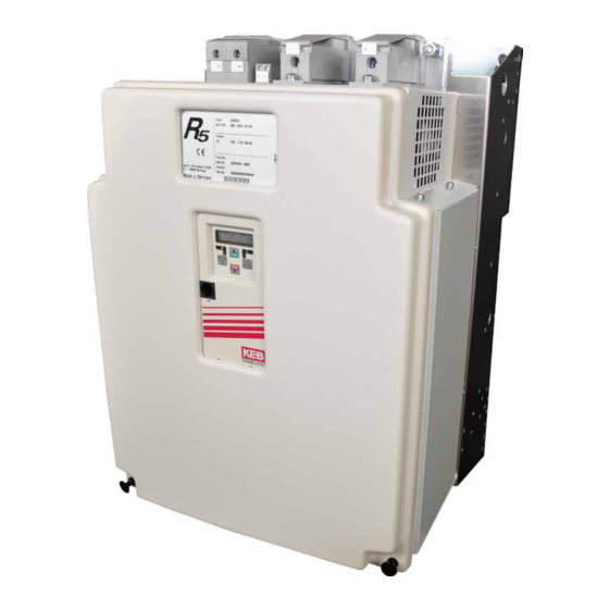
With R5-C COMBIVERT you have acquired a DC supply unit with the highest demands on security and reliability. This instruction manual describes the supply unit KEB COMBIVERT R5-C of the 400-V in a range of 30 kW...250 kW. 2.1 Specified application The COMBIVERT R5-C serves exclusively for supply of frequency inverters with DC supply. -
Page 8: Technical Data
Product description Technical data Rectifier size Housing size Chargeable inverter power [kW] DC nominal output current Max. short time current OL current 1037 Input current 79,8 147,5 Mains voltage [V AC 305…504 +/- 0% Phases Output voltage [V DC] 430…713 Maximal permissible mains fuse t mains fuse <19.100 <128.000 <236.000 <423.000 <1.062.000 <1.062.000 Supply line cross section (min) -
Page 9: Installation
Installation Installation Unit Installation 3.1.1 Dimensions Ø F Housing 3.1.2 Installation Instructions The COMBIVERT R5 is provided for vertical installation. The following minimum distances must be observed: GB - 9... -
Page 10: Connection Of The Power Unit
Installation Connection of the Power Unit 3.2.1 Mains Connection of the Supply Unit • absolutely use a line reactor • in case of interconnected operation with several supply units consider information sheet 00.R5.0DM-I000 ! Switching at the input without waiting of an under-potential error (E.UP) causes high wear of the switching contacts. -
Page 11: Terminal Strips Of The Power Circuit
Installation 3.2.2 Terminal strips of the power circuit All terminal strips following the requirements of the EN 60947-7-1 (IEC 60947- 7-1) Connection terminals Terminal in acc. with table 3.2.2.1 Name Function L1, L2, L3 3-phase mains connection Connection for braking resistor PA, PB DC link output +, –... -
Page 12: Connection Of A Braking Resistor
Installation 3.2.3 Connection of the Braking Resistor It is absolutely necessary to monitor the braking resistance temperature switch to record a braking resistance overheat. The overheat may be caused by: • incorrect dimensioning of the braking resistance • the input voltage being too high The current of the brake transistor is monitored additionally. -
Page 13: Connection Of A Temperature Detection
Installation 3.2.4 Connection of a Temperature Detection An external temperature sensor/switch can be connected to the terminals T1, t2 . The supply unit switches off with the error message E.OH during tripping. As standard the evaluation at terminals T1 and T2 is switched off and must be activated if necessary (application mode Pn.12=“7“). -
Page 14: Installation And Connection
Installation and connection Installation and connection Control Card Version C 4.1.1 Assignment of the Terminal Strip X2A 1 2 3 4 5 6 7 8 9 10 11 12 13 14 15 16 17 18 19 20 21 22 23 24 25 26 27 28 29 Function Name Explanation... -
Page 15: Control Connection
Installation and connection 4.1.2 Connection of the control In order to avoid malfunctions caused by interference voltage supply at the control inputs, the following instructions must be observed: • Use shielded/drilled cables • Lay shield on one side of the inverter onto earth potential •... -
Page 16: Operation Of The Unit
An operator is necessary as accessories for local or external (Option: cable 00.F5.0C0-1xxx) programming of the frequency inverter KEB COMBIVERT. In order to avoid malfunctions the frequency inverter must be brought into status nOP before plug-on/remove of the operator (open control release). During starting of the frequency inverter it always starts with the last stored values/factory setting. -
Page 17: Keyboard
Operation of the Unit 5.1.1 keyboard When switching on KEB COMBIVERT R5 the value of parameter CP.1 is displayed. (change-over of the keyboard function see Drivemode) The function key is FUNC. used to change between parameter value and SPEED parameter number. -
Page 18: Parameter Summary
Operation of the Unit Parameter summary The CP parameters are one of the parameter selection defined by KEB. You need an application manual in order to get access to the entire parameters. Display Parameter Setting range Resolution Fact. setting CP. 0 Password input 0…9999... -
Page 19: Parameter Description
Operation of the Unit Parameter Description The following parameters serve for the functional monitoring during operation. CP. 1 The status display indicates the actual operating condition of the inverter. Inverter state Possible displays and their meaning: "no Operation" Starting terminal not bridged, thyristors blocked, output voltage = 0 V "run"... - Page 20 Operation of the Unit CP. 8 This display enables a detection of short-term voltage peaks, as the highest DC - output voltage / value that occurred is stored. peak value The peak value can be reset with UP or Down when the unit is switched on. Switching off the unit deletes the peak value.
-
Page 21: Functional Description
Functional Description Functional Description Block Diagram of the Supply Unit Ready for ope- ration Pre-warning Heat sink temperature 24 VDC B6 Charge Rectifier GTR7 Current supply Electronics (Option) 560 VDC Main thyristors DC-fuses (Option) Current measurement Switch-on procedure The charging procedure of the connected frequency inverters starts with releasing mains voltage to the input terminals L1, l2, L3 and starting of the control. -
Page 22: Error During Operation
Functional Description Error During Operation An error signal is output on tripping the protective functions and the thyristors are switched off. The following operating conditions are supervised: • Heat sink temperature • Current • Ground fault by differential current measurement First a prewarning is given out if the heat sink temperature is too high, so a controlled deceleration of the unit is possible. -
Page 23: Power-On With Normal Conditions
Functional Description 6.6.1 Power-on with Normal Conditions Power GF-Test charge Status Output ready Output CP.6 Actual DC Voltage du<50V CP.7 DC Output Voltage t=104ms Precharge Precharge t=24ms Thyristor Output error GB - 23... -
Page 24: Ground Fault During Power-On To +Dc
Functional Description 6.6.2 Ground Fault during Power-on to +DC Power GF-Test E.GF1 Status Output ready Output Output error Precharge Precharge Thyristor GB - 24... -
Page 25: Charge Time Exceeding During Power-On
Functional Description 6.6.3 Charge Time Exceeding during Power-on Power GF-Test charge Error - charge time out Status Output ready Output Output error CP.6 Actual DC Voltage du>50V CP.7 DC Output Voltage Precharge Thyristor GB - 25... -
Page 26: Output Error During Operation
Functional Description 6.6.4 Output error during Operation Error rectifier output Status Output ready Output Output error CP.6 Actual DC Voltage du>200V CP.7 DC Output Voltage Thyristor GB - 26... -
Page 27: Phase Error During Operation
Functional Description 6.6.5 Phase Error during Operation (E.UPh) phase failure occurs Status Error phase failure 0,5•In 60s max. Output ready Output Output warning Output error Thyristor The utilization of L1, L2 und L3 is compared with ru.13. If after triple scan- ning (12 ms) a difference of >15 % of one phase to CP.13 is detected, then •... - Page 28 +39 02 3353531 • fax: +39 02 33500790 net: www.keb.de • mail: kebitalia@keb.it KEB Power Transmission Technology (Shanghai) Co.,Ltd. No. 435 Qianpu Road, Chedun Town, Songjiang District, KEB Japan Ltd. Shanghai 201611, P.R. China 15–16, 2–Chome, Takanawa Minato-ku fon: +86 21 37746688 • fax: +86 21 37746600...
Need help?
Do you have a question about the COMBIVERT R5-C and is the answer not in the manual?
Questions and answers