Table of Contents
Advertisement
Quick Links
Advertisement
Table of Contents

Related Manuals for Aeroflex ProLock 2201


Summary of Contents for Aeroflex ProLock 2201
- Page 1 2201 ProLock 3G Test Set for Service Getting Started Manual AG295003 Issue 1...
- Page 3 No part of this document may be reproduced or transmitted in any form or by any means, electronic or mechanical, including photocopying, or recorded by any information storage or retrieval system, without permission in writing by Aeroflex Ltd. (hereafter referred to throughout the document as 'Aeroflex'). Printed in the UK Document no.
- Page 4 We reserve the right to make design changes without notice. Trademarks Aeroflex is a trademark of Aeroflex Incorporated in the U.S.A. and other countries. Specifications, terms and conditions are subject to change without notice.
-
Page 5: Table Of Contents
Table of contents About this guide Purpose and scope ....... . . VIII Assumptions . - Page 6 Table of contents Environmental conditions ......3 Options ..........4 2231 GSM Option .
- Page 7 Table of contents Appendix B Software licence and warranty Publication history 2201 ProLock...
- Page 8 Table of contents 2201 ProLock...
- Page 9 About this guide This section contains the following information: – ’Purpose and scope’ on page viii – ’Assumptions’ on page viii – ’Related information’ on page viii – ’Technical assistance’ on page ix – ’Conventions’ on page ix 2201 ProLock...
-
Page 10: Purpose And Scope
ProLock’s features and capabilities. This guide includes task- based instructions that describe how to install and use the 2201 ProLock. Additionally, this guide provides a description of Aeroflex’s warranty, services, and repair information, including terms and conditions of the licensing agreement. Assumptions This guide is intended for novice and intermediate users who want to use the 2201 ProLock effectively and efficiently. -
Page 11: Technical Assistance
Technical assistance Technical assistance If you need assistance or have questions related to the use of this product, call Aeroflex’s technical support. Contact numbers are given at the end of this document. Conventions This guide uses naming conventions and symbols, as described in the following tables. - Page 12 About this guide Conventions Table 2 Keyboard and menu conventions Description Example A plus sign + indicates Press Ctrl+s simultaneous keystrokes. A comma indicates consec- Press Alt+f,s utive keystrokes. A slanted bracket indicates On the menu bar, click Start > Program Files. choosing a submenu from menu.
-
Page 13: Safety Notes
Safety notes This chapter provides the safety notes for the 2201 ProLock. Topics discussed in this chapter include: – ’Precautions’ on page xii – ’External power supply’ on page xiv – ’During maintenance and repair’ on page xv – ’Additional cautions’ on page xv –... -
Page 14: Precautions
Safety notes Precautions Precautions These terms have specific meanings in this manual: Information to prevent personal injury. Information to prevent damage to the equip- ment. Important general information. Symbols used The meaning of hazard symbols appearing on the equipment and in the documentation is as follows: on this product Symbol... -
Page 15: Suitability For Use
This equipment has been designed and manufactured by Aeroflex to perform measurements on RF systems. If the equip- ment is not used in a manner specified by Aeroflex, or if it is damaged, the protection provided by the equipment may be impaired. -
Page 16: External Power Supply
Do not try to open the power supply. There are no serviceable parts inside. If the power supply is defective you can obtain a new one from Aeroflex (order number AG860224). Use the supplied power cord or an appropriate replacement. -
Page 17: During Maintenance And Repair
Safety notes During maintenance and repair Do not attempt to service this product yourself Risk of electric shock Opening or removing covers of the external power supply may expose you to dangerous high voltage points and other haz- ards. Refer all servicing to qualified service personnel. During maintenance and repair Maintenance and repair is only allowed to specially trained service technicians. - Page 18 Safety notes Additional cautions CAUTION Operate the instrument within the temperature range from 5°C (40°F) to 40°C (104°F) only. Operation outside this range will lead to invalid results. This product is designed for indoor use. Exposure to water may damage the instrument, so protect it against moisture when using it outdoors.
-
Page 19: Declaration Of Eu Conformity
Safety notes Declaration of EU Conformity Declaration of EU Conformity All Aeroflex Ltd products are in compliance with appropriate Directives for CE marking utilizing standards as published in the Official Journal of the European Union; Reference: Safety standard EN 61010-1 and EMC standard EN 61326-1. - Page 20 Safety notes Declaration of EU Conformity xviii 2201 ProLock...
-
Page 21: Overview
Overview Chapter 1 This chapter provides a general description of the 2201 ProLock. Topics discussed in this chapter include the following: – ’About the 2201 ProLock’ on page 2 – ’Features and capabilities’ on page 3 – ’Options’ on page 4 2201 ProLock... -
Page 22: About The 2201 Prolock
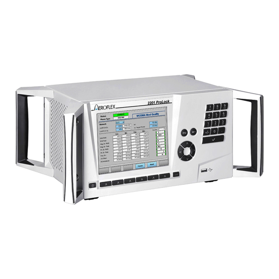
About the 2201 ProLock About the 2201 ProLock Aeroflex’s 2201 ProLock is a test instrument for 3G mobile phones and wireless data cards. Level 1 and level 2 service shops use the ProLock to quickly test wireless devices, perform smaller repairs and bill manufacturers for warranty claims. -
Page 23: Features And Capabilities
Chapter 1 Overview Features and capabilities Features and capabilities Affordable mobile phone test set for point-of-return and service tests. Separates defective from faultless phones. RF connector on the back for clear and tidy work bench. Select any or all of these systems: GSM, GPRS, EPGRS (EDGE), WCDMA and HSDPA. -
Page 24: Options
Chapter 1 Overview Options Options 2231 GSM The 2231 GSM Option performs the necessary GSM call processing and measurements on a voice channel or a test Option channel (loopback channel). Measurements include: – Output power – Power vs. time – RMS and peak phase error –... -
Page 25: 2234 Wcdma Option
License the coupling device. Aeroflex offers an update service of the coupling factors for the latest models. These coupling factors are valid for the antenna connection between the phone and the Aeroflex 4916/4918 Antenna Coupler installed in an Aeroflex RF shield. -
Page 26: 2261 Autotest Option
Chapter 1 Overview Options 2261 Autotest The Autotest option allows for complete automated tests without a separate PC, but with similar ease of use as 7310 Lector- Option Scriptor. The same scripts can be used for Lector and for Autotest on the ProLock. -
Page 27: System Architecture
Aeroflex’s 4921 RF Shield. This device features very high attenuation between incoming and outgoing signal, fulfilling the requirement of 80 dB shielding for most state-of-the-art communication systems. - Page 28 Chapter 1 Overview System architecture 2201 ProLock...
-
Page 29: Installation
Installation Chapter 2 This chapter describes how to set up the 2201 ProLock. The topics discussed in this chapter are as follows: – ’Scope of delivery’ on page 10 – ’Software requirements’ on page 10 – ’Hardware requirements’ on page 10 –... -
Page 30: Scope Of Delivery
The following are hardware requirements as well as hardware recommendations for achieving the most reliable test results. If you want to use the 2201 ProLock with one of the products of the Lector and Scriptor family of testing products, Aeroflex specifications recommends the following mininum PC specifications: –... -
Page 31: Rf Connection And Shielding
– RS-232 RF connection An antenna coupler or cable connection to the device under test is required. Aeroflex recommends the use of the 4916 or 4918 and shielding Antenna Coupler. For proper shielding and more reliable results, an Aeroflex RF shield is recommended, for example, 4932. When using the coupler and shield, an RF cable is required for connecting them. -
Page 32: Setting Up The Hardware
3 Connect the RF I plug on ProLock’s rear panel with the RF shield using a double-shielded RF cable. If you do not intend to use the an Aeroflex RF shield, connect the 2201 ProLock to the coupling device of your choice. 2201 ProLock... -
Page 33: Installing The Software
Or use the standard LAN cable with LAN-to-USB adapter that is included in the deliv- ered items to connect the ProLock to a PC directly. Installing the software 1 Go to the Aeroflex website and access the Lector and Scriptor software at http://www.aeroflex.com/ats/products/product/ Communications_Test/Cellular_Parametric_Test/ 7310_Lector_--and--_Scriptor_Family~737.html... - Page 34 Chapter 2 Installation Installing the software If you are using a Windows Vista PC, the operating system may ask you for USB driver software after connecting the 2201 ProLock over the USB for the first time. In this case, indicate the following directory for the USB driver: ProLock-USB-Vista.
-
Page 35: Configuring The Software
Chapter 2 Installation Configuring the software Each device can be defined as follows by selecting the appro- priate entries: Table 5 Transport input fields in the Connection menu Transport Parameters Remarks type USB/ COM port For RS-232 connections, use the RS-232 (range 1 –... - Page 36 Chapter 2 Installation Configuring the software 2201 ProLock...
-
Page 37: Operation
Operation Chapter 3 This chapter describes the functionality of the instrument. Topics discussed in this chapter are as follows: – ’Connecting the 2201 ProLock’ on page 18 – ’Powering the unit’ on page 22 – ’Using the front panel’ on page 23 –... -
Page 38: Connecting The 2201 Prolock
Chapter 3 Operation Connecting the 2201 ProLock Connecting the 2201 ProLock The 2201 ProLock offers different connectors for a variety of applications. The following section describes the connectors available and provides information on technical data and applica- tion purposes. The 2201 ProLock can be operated from an external DC source such as the power supply that is delivered with ProLock, or a car battery. -
Page 39: Usb
If you have a 50 Ω shielded RF cable with a BNC connector (male), use an N to BNC adapter to connect the cable to ProLock. Aeroflex offers an appropriate adapter. CAUTION The maximum input power level at the RF connector is 3.5 W (35 dBm) continuous or burst level. -
Page 40: Lan, Usb-A
Chapter 3 Operation Connecting the 2201 ProLock LAN, USB-A There is an RJ-45 LAN plug on the right-hand side of the rear panel. Additional USB plugs can be found below the LAN plug. The 2201 ProLock can be controlled from an external computer via a local area network (LAN), using a TCP/IP connection at 10 or 100 Mbit/s. -
Page 41: Ref In
Chapter 3 Operation Connecting the 2201 ProLock RS-232 This 9-pin sub-D connector on the rear panel of the 2201 ProLock can be used to control the instrument remotely via a serial interface (RS-232). The command set and the responses conform to the SCPI standard and are explained in the user guide. The RS-232 connector can also be used to load and store results and settings and to update the operating software. -
Page 42: Powering The Unit
Chapter 3 Operation Powering the unit Powering the unit Once the 2201 ProLock is connected to AC power and the unit under test, the instrument can be powered on with the power switch on the front panel (left-hand side). Once the instrument is switched on, it takes a couple of seconds for the instrument to load and start its firmware. -
Page 43: Using The Front Panel
Chapter 3 Operation Using the front panel Using the front panel The LCD screen shows the menus that guide you through config- uration and measurements when the 2201 ProLock is switched on and the operating software is loaded. The menus consist of different sections as follows: 2201 ProLock... - Page 44 Chapter 3 Operation Using the front panel The top row shows the signaling and instrument status on the left. On the right-hand side, the top row displays the current menu name. The bottom row displays the meaning of the softkeys that are located beneath the LCD screen.
-
Page 45: Keypad
Chapter 3 Operation Using the front panel Keypad The front panel of the 2201 ProLock has a number of keys, as follows: On-off switch See ’Powering the unit’ on page Softkeys The softkeys are the six keys below the LCD screen. The meaning depends on the currently active menu and is displayed on the screen, above the softkeys. -
Page 46: Navigating The User Interface
Chapter 3 Operation Navigating the user interface Entry keys You can open the currently highlighted input field and enter new values or text just by using the entry keys. The Enter key (marked with a tick) is used to accept the current value. -
Page 47: Cleaning
Chapter 3 Operation Cleaning Cleaning Before starting any cleaning, switch off the instrument and disconnect it from the supply by removing the power cord. Case exterior: use a soft cloth moistened with water to clean the case; do not use aerosol or liquid solvent cleaners. LCD: take care not to scratch the LCD during use or when cleaning. - Page 48 Chapter 3 Operation Cleaning 2201 ProLock...
-
Page 49: Repair
If possible, return the equipment using the original shipping container and material. Additional Aeroflex shipping containers are available from Aeroflex on request. If the original container is not available, the unit should be carefully packed so that it will not... -
Page 50: Appendix A Repair
Appendix A Repair Equipment return instructions be damaged in transit. Aeroflex is not liable for any damage that may occur during shipping. The customer should clearly mark the Aeroflex-issued RA or reference number on the outside of the package and ship it prepaid and insured to Aeroflex. - Page 51 SOFTWARE LICENCE AND WARRANTY This document is an Agreement between the user of this Licensed Software, the Licensee, and Aeroflex Limited (‘Aeroflex’), the Licensor. By installing or commencing to use the Licensed Software you accept the terms of this Agreement. If you do not agree to the terms of this Agreement do not use the Licensed Software.
- Page 52 Aeroflex’s 3000 Series PXI product range 2. LICENCE FEE The Licensee shall pay the Licence Fee to Aeroflex in accordance with the terms of the contract between the Licensee and Aeroflex. 3. TERM This Agreement shall be effective from the date of receipt or download (where applicable) of the Licensed Software by the Licensee and shall continue in force until terminated under the provisions of Clause 8.
- Page 53 Appendix B Software licence and warranty Neither the Licensed Software nor any information provided by Aeroflex to the Licensee nor any licence and rights granted hereunder, sold, leased, assigned, sublicensed, electronically distributed, timeshared or otherwise transferred, in whole or in part by the Licensee other than as specified in this Licence without the prior written consent of Aeroflex.
- Page 54 PXI Drivers and PXI Executable Applications as necessary for use with 3000 Series PXI modules acquired by the Licensee from Aeroflex or its authorized distributor or reseller provided that the Licensee may not sell or charge a fee for the PXI Drivers and PXI Executable Applications.
- Page 55 Licensee shall indemnify Aeroflex against all claims costs and damages incurred and that Aeroflex is given prompt written notice of such claim and given information, reasonable assistance and sole authority to defend or settle such claim on behalf of the Licensee. In the...
- Page 56 Licensed Software at the commencement of this Agreement. Aeroflex shall not be liable to the Licensee for any loss of use or for loss of profits or of contracts arising directly or indirectly out of any such infringement of patent, registered design, trademark or copyright.
- Page 57 252.227-7013 or subparagraphs (c)(1) and (2) of the Commercial Computer Software-Restricted Rights at 48 CFR 52.227-19, as applicable. 12. NOTICES Any notice to be given by the Licensee to Aeroflex shall be addressed to: Aeroflex Limited, Longacres House, Six Hills Way, Stevenage, SG1 2AN, 13. LAW AND JURISDICTION This Agreement shall be governed by the laws of England and shall be subject to the exclusive jurisdiction of the English courts.
- Page 58 Appendix B Software licence and warranty 2201 ProLock...
- Page 59 New layout. Issue 1 Safety update revision at Stevenage. Aeroflex and its logo are trademarks of Aeroflex Incorporated. All other trademarks and registered trademarks are the property of their respective owners. Specifications, terms and conditions are subject to change without notice.
- Page 60 As we are always seeking to improve our products, the information in this document gives only a general indication of the product capacity, performance and suitability, none of which shall form part of any contract. We reserve the right to make design changes without notice. All trademarks are acknowledged. Parent company Aeroflex, Inc. web: www.aeroflex.com Email: info-test@aeroflex.com...
Need help?
Do you have a question about the ProLock 2201 and is the answer not in the manual?
Questions and answers