Table of Contents
Advertisement
Quick Links
TCAS Test Set
RGS-2000NG
Operation Manual
Issue-6
EXPORT CONTROL WARNING: This document contains controlled technical data under the
jurisdiction of the Export Administration Regulations (EAR), 15 CFR 730-774. It cannot be
transferred to any foreign third party without the specific prior approval of the U.S. Department of
Commerce, Bureau of Industry and Security (BIS). Violations of these regulations are punishable
by fine, imprisonment, or both.
Advertisement
Chapters
Table of Contents

Related Manuals for Aeroflex RGS-2000NG


Summary of Contents for Aeroflex RGS-2000NG
- Page 1 TCAS Test Set RGS-2000NG Operation Manual Issue-6 EXPORT CONTROL WARNING: This document contains controlled technical data under the jurisdiction of the Export Administration Regulations (EAR), 15 CFR 730-774. It cannot be transferred to any foreign third party without the specific prior approval of the U.S. Department of Commerce, Bureau of Industry and Security (BIS).
- Page 2 OP ER AT ION MAN U AL T C A S T ES T S ET RGS-2 000NG P UB LIS HE D BY Aer ofle x CO P YR IGHT © Aer ofl ex 2018 All rig hts r eserved . No pa rt of t his pu blicati on may b e re produ ced, st ore d in a re tri eval system, or tr ansmitte d in any f orm or by any means, elect roni c, mechan ical, photo co pying, recor ding or other wi se wit hout the pri or p ermission of the p ublisher .
- Page 3 OP ER AT IO N MAN UA L RG S- 2000N G E l e c t r o m a g n e t i c C o m p a t i b i l i t y : F o r c o n t i n u e d E M C c o mp l i a n c e , a l l e x t e r n a l c a b l e s m u s t b e s h i e l d e d a n d t h r e e m e t e r s o r l e ss i n l e n g t h .
- Page 4 OP ER AT IO N MAN UA L RG S- 2000N G T H I S P A G E I N T E N T I O N A L L Y L E F T B L A N K . S u b j e ct t o E x p o r t C o n tr o l , s ee C o ve r P a g e f o r d e t ai l s .
- Page 5 OP ER AT IO N MAN UA L RG S- 2000N G SAFETY INFORMATION S A F E T Y F I R S T : T O A L L O P E R A T I O N S P E R S O N N E L R E F E R A L L S E R V I C I N G O F U N I T T O Q U A L I F I E D T E C H N I C A L P E R S O N N E L .
- Page 6 OP ER AT IO N MAN UA L RG S- 2000N G S A F E T Y F I R S T : T O A L L O P E R A T I O N S P E R S O N N E L ( C O N T ) C A U T I O N : S I G N A L G E N E R A T O R S C A N B E A S O U R C E O F E L E C T R O M A G N E T I C I N T E R F E R E N C E ( E M I ) T O C O M M U N I C A T I O N R E C E I V E R S .
- Page 7 OP ER AT IO N MAN UA L RG S- 2000N G DECLARATION OF CONFORMITY T h e D e cl a r at i o n o f C o n f or mi t y C e r t i f i c a t e i n c l u d e d w i t h t h e u n i t s h o u l d r e m a i n w i t h t h e u n i t . A e r o f l e x r e c o m me n d s t h e o pe r a t o r r e p r o d u c e a c o p y o f t h e D e c l a r a t i o n o f C o n f o r m i t y C e r t i f i ca t e t o b e s t o r e d w i t h t h e O p e r a t i o n M a n u a l f o r f u t u r e r e f e r e n c e .
- Page 8 OP ER AT IO N MAN UA L RG S- 2000N G T H I S P A G E I N T E N T I O N A L L Y L E F T B L A N K . S u b j e ct t o E x p o r t C o n tr o l , s ee C o ve r P a g e f o r d e t ai l s .
- Page 9 OP ER AT IO N MAN UA L RG S- 2000N G TABLE OF CONTENTS TIT LE CHAPTER/SECTION Titl e / Cop yright Pa ge St atement s S afet y Inf ormat ion Decl arat ion of C onfor mity Table of Con tents Int roduct ion Ser vice U pon Recei pt of Mate rial...
- Page 10 OP ER AT IO N MAN UA L RG S- 2000N G T H I S P A G E I N T E N T I O N A L L Y L E F T B L A N K . S u b j e ct t o E x p o r t C o n tr o l , s ee C o ve r P a g e f o r d e t ai l s .
- Page 11 OP ER AT IO N MAN UA L RG S- 2000N G INTRODUCTION This ma nual co ntains oper ating instr uction s for th e R GS -20 00NG. Aer ofle x str ongly r ecommends that perso nnel b e th oroug hly fa mi liar wit h t he cont ents of t his manu al bef ore att empting to opera te t he equipme nt.
- Page 12 OP ER AT IO N MAN UA L RG S- 2000N G T H I S P A G E I N T E N T I O N A L L Y L E F T B L A N K . S u b j e ct t o E x p o r t C o n tr o l , s ee C o ve r P a g e f o r d e t ai l s .
-
Page 13: Table Of Contents
OP ER AT IO N MAN UA L RG S- 2000N G TABLE OF CONTENTS CO N TEN T SECTION PAGE S E CT I O N 1 - DE S CR IP T I O N 1- 1 Genera l D escript ion a nd C apabil ities 1-1-1 Description . - Page 14 OP ER AT IO N MAN UA L RG S- 2000N G CO N TEN T SECTION PAGE Transponder Test Mode ..........1-2-3 ..111 3.4.1 Transponder Settings Screen .
- Page 15 OP ER AT IO N MAN UA L RG S- 2000N G CO N TEN T SECTION PAGE Remo te Oper atio n 1-2-5 Overview ............1-2-5 ..17 Accepted GPIB Commands .
- Page 16 OP ER AT IO N MAN UA L RG S- 2000N G CO N TEN T SECTION PAGE RTCA/DO-260 Test Commands ......... 1-2-5 ..38 5.8.1 Generator Parameters .
- Page 17 OP ER AT IO N MAN UA L RG S- 2000N G CO N TEN T SECTION PAGE 5.12 Unit Commands ........... . 1-2-5 ..159 5.12.1 Hardware Version Request .
- Page 18 OP ER AT IO N MAN UA L RG S- 2000N G CO N TEN T SECTION PAGE S E CT I O N 3 - SP E C IFI CA T IO NS 1- 3 T ransmit ter 1-3-1 Frequency .
- Page 19 OP ER AT IO N MAN UA L RG S- 2000N G CO N TEN T SECTION PAGE AP P E ND IX A - C O NN E CT O R P I N- O U T T AB L E S I/O Connectors - FRONT PANEL .
- Page 20 OP ER AT IO N MAN UA L RG S- 2000N G T H I S P A G E I N T E N T I O N A L L Y L E F T B L A N K . S u b j e ct t o E x p o r t C o n tr o l , s ee C o ve r P a g e f o r d e t ai l s .
- Page 21 RGS-2000NG Main “Home” Screen ......1-2-1 ..
- Page 22 OP ER AT IO N MAN UA L RG S- 2000N G FIG U RE # SECTION PAGE Figure 1.2.3 - 42 TCAS Intruders DF16 Replies Screen ......1-2-3 ..50 Figure 1.2.3 - 43 TCAS Intruders DF16 Reply MV Fields Screen .
- Page 23 OP ER AT IO N MAN UA L RG S- 2000N G FIG U RE # SECTION PAGE Figure 1.2.3 - 94 TCAS Video Blocks Video Waypoints ......1-2-3 ..105 Figure 1.2.3 - 95 TCAS Video Blocks Video Data Bit .
- Page 24 OP ER AT IO N MAN UA L RG S- 2000N G FIG U RE # SECTION PAGE Figure 1.2.3 - 145 Transponder Interrogation With CW Screen ....1-2-3 ..148 Figure 1.2.3 - 146 Transponder Interrogation with CW (Mode A) Softkey Menu .
- Page 25 OP ER AT IO N MAN UA L RG S- 2000N G LIST OF TABLES TAB LE # SECTION PAGE Table A - 3 ATE LINE Connector Pin-Out Table ......A-1 ..6 Table A - 4 Auxiliary Control Connector Pin-Out Table.
- Page 26 OP ER AT IO N MAN UA L RG S- 2000N G T H I S P A G E I N T E N T I O N A L L Y L E F T B L A N K . S u b j e ct t o E x p o r t C o n tr o l , s ee C o ve r P a g e f o r d e t ai l s .
- Page 27 OP ER AT IO N MAN UA L RG S- 2000N G SERVICE UPON RECEIPT OF MATERIAL U n p a c k i n g Spe ci al-de sign packing mater ial inside th e shi pping conta iner pr ovides maximum p rote ction for t he RG S- 2000N G.
- Page 28 OP ER AT IO N MAN UA L RG S- 2000N G F ig u r e 1 P a c k a g i n g D i a g r a m S u b j e ct t o E x p o r t C o n tr o l , s ee C o ve r P a g e f o r d e t ai l s . SERVICE UPON RECEIPT PAGE 2 JAN 1/18...
- Page 29 OP ER AT IO N MAN UA L RG S- 2000N G S T A N D A R D I T E M S D E S C R I P T I O N P A R T N U M B E R Q T Y RG S -2000 NG T CA S T est S et 1 1 3 9 5 6...
- Page 30 OP ER AT IO N MAN UA L RG S- 2000N G O P T I O N A L I T E M S D E S C R I P T I O N O P T I O N N U MB E R P A R T N U MB E R Rockw ell Col lins C ompati bility Op tion R G S N G O P T 0 1...
- Page 31 OP ER AT IO N MAN UA L RG S- 2000N G SECTION 1 - DESCRIPTION 1. GENERAL DESCRIPTION AND CAPABILITIES DESCRIPTION The R G S-2 000N G T CA S Test Set i s a n RF S ignal Gene rato r/R eceiver for testin g TCA S ( Tra ffic A lert and Col lision Avoida nce S yst em) wit h an optio n availa ble f or testin g Tr anspond er L RU s.
- Page 32 OP ER AT IO N MAN UA L RG S- 2000N G FUNCTIONAL CAPABILITIES (CONT) • Equ ipment tested : • TC AS Co mp uter s • AD S- B I N Rece ivers • AD S- B I N Gr ound St ation Re ce ivers •...
- Page 33 OP ER AT IO N MAN UA L RG S- 2000N G SECTION 2 - OPERATION 1. INSTALLATION GENERAL 1.1.1 BENCH USE When used i n a B ench enviro nment, the RG S -2000 NG sho uld be placed on a dry, level wo rk sur face. 1.1.2 RACK MOUNT Con tact Cust omer Ser vice fo r in for ma tion about insta lling the R G S- 2000N G in an equ ipment rack.
- Page 34 OP ER AT IO N MAN UA L RG S- 2000N G 1.2.5 CAUTION AND WARNING LABELS Extr eme ca re sh ould b e exer cised w hen perf orming any o perat ions p recede d by a CA U TION or WAR N ING label.
- Page 35 OP ER AT IO N MAN UA L RG S- 2000N G POWER ON/OFF PROCEDURES 1.5.1 POWER ON PROCEDURE Ref er to 1.2 .2. - Co ntro ls, C onne ctors and Ind icator s , Figu re 1.2. 2 - 1 and Figu re 1.2. 2 - 2 for lo cation of contr ols, connecto rs or ind icator s.
- Page 36 OP ER AT IO N MAN UA L RG S- 2000N G 1. 6 RE MO TE (V NC) C ON NEC TIO N The RG S- 2000N G can be con trol led usi ng an exter nal H ost Con tro ller such as a comput er, tabl et o r Smar tphon e and a T ight V NC Vie wer client .
- Page 37 OP ER AT IO N MAN UA L RG S- 2000N G 1.6.2 ESTABLISH VNC CONNECTION STE P PROCEDURE Ver ify the H ost Con tro ller and T est S et are both connect ed t o the same L AN . O btain the Test Set ’s IP A ddress (r efer to 3.6.
- Page 38 OP ER AT IO N MAN UA L RG S- 2000N G 1.6.3 TROUBLESHOOTING VNC CONNECTION 1. 6 .3 .1 V er i f y Ne t w or k C onne c t ion s • Ver ify the H ost Con trol ler (i .e., compu ter, t ablet , Smart phone ) and Test Se t are connect ed to the same LA N.
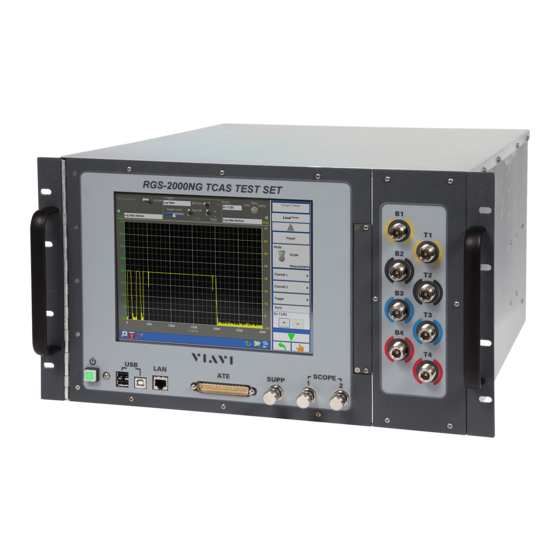
- Page 39 OP ER AT IO N MAN UA L RG S- 2000N G 2. CONTROLS, CONNECTORS AND INDICATORS FRONT PANEL F i g u r e 1 . 2 . 2 - 1 R G S - 2 0 00 N G F r o n t P a ne l Ref er to F igur e 1.
- Page 40 OP ER AT IO N MAN UA L RG S- 2000N G REAR PANEL F i g u r e 1 . 2 . 2 - 2 R G S - 2 0 0 0 N G R e a r P a n e l Ref er to F igur e 1.
- Page 41 OP ER AT IO N MAN UA L RG S- 2000N G 3. RGS-2000NG SCREENS CO N TEN T SECTION PAGE Screen Layout and Navigation ......... . 1-2-3 ..7 3.1.1...
- Page 42 OP ER AT IO N MAN UA L RG S- 2000N G CO N TEN T SECTION PAGE 3.3.7 TCAS Scenario Screen ..........1-2-3 ..40 3.3.7.1 TCAS Scenario Intruders Screen .
-
Page 43: Co N Ten Tsection Page
OP ER AT IO N MAN UA L RG S- 2000N G CO N TEN T SECTION PAGE 3.3.7.2 TCAS Scenario Ground Station Screen ......1-2-3 ..98 3.3.7.2.1 TCAS Ground Station Interrogation Screen . - Page 44 OP ER AT IO N MAN UA L RG S- 2000N G CO N TEN T SECTION PAGE 3.4.4.4.4 Transponder Block Transmission Measured Pulse Softkey Menu ..1-2-3 ..147 3.4.4.4.5 Transponder Block Transmission Receiver Summary Screen .
- Page 45 OP ER AT IO N MAN UA L RG S- 2000N G CO N TEN T SECTION PAGE System Screen ........... . . 1-2-3 ..176 3.6.1 Network Connections Screen .
- Page 46 OP ER AT IO N MAN UA L RG S- 2000N G T H I S P A G E I N T E N T I O N A L L Y L E F T B L A N K . S u b j e ct t o E x p o r t C o n tr o l , s ee C o ve r P a g e f o r d e t ai l s .
-
Page 47: Screen Layout
OP ER AT IO N MAN UA L RG S- 2000N G 3. 1 SC REE N LAY O UT AND NAV I G ATI ON NO TE : TH E S CR EE N IMA GE S SH OW N IN TH IS SE CTI O N A R E R EP RE SE NT ATI O NS O F T HE SC RE EN S TH AT US ER S MA Y EN CO U NT ER WH EN U SIN G TH E TES T S ET . -
Page 48: Main Display Area
OP ER AT IO N MAN UA L RG S- 2000N G 3.1.2 MAIN DISPLAY AREA The content of the Main D ispla y Ar ea cha nges de pending on t he sel ected test mode an d select ed funct ion. -
Page 49: Status/Task Bar
OP ER AT IO N MAN UA L RG S- 2000N G 3.1.4 STATUS/TASK BAR The b lue bar locat ed at t he bot tom of the S creen contai ns funct ion but tons an d displays in dicator s w hich provi de a visual f eedback about the system’s st ate and ha rdw are connect ions. -
Page 50: Data Entry Modes
OP ER AT IO N MAN UA L RG S- 2000N G 3.1.5 DATA ENTRY MODES 3. 1 .5 .1 De v ic e M ode D at a E n t ry When Devi ce Mode is select ed as the primary means of editing and navigating the Test Set’s Screens, ar row s are displaye d next to each set ting fiel d on the Sc re ens. - Page 51 OP ER AT IO N MAN UA L RG S- 2000N G 3. 1 .5 .2 Touc h Scr e en D ata Ent ry T ool s Wh en T ouch S creen Mode is sele ct ed, pre ssi ng a setti ng f ield displays vi rtua l on- screen cont rols which are used to de fine para me ters.
-
Page 52: Main "Home" Screen
OP ER AT IO N MAN UA L RG S- 2000N G 3. 2 MAI N “HOME ” SCR EE N Figur e 1. 2.3 - 8 show s an example of t he R G S-2 000N G Main S creen and Sof tkey Menu sequen ce. T his screen is t he Te st S et’s “... -
Page 53: Tcas Test Mode
OP ER AT IO N MAN UA L RG S- 2000N G 3. 3 TCAS TES T MODE The TCA S Test Mode Mai n Scr een allow s the user to select fro m vario us TC AS system test functi ons. The TCA S Home Scr een d isplays al l curr ent ly insta lled co mp atibil ity op tions. -
Page 54: Tcas Settings Screen
OP ER AT IO N MAN UA L RG S- 2000N G 3.3.1 TCAS SETTINGS SCREEN The TCAS Settings Screen a llow s the user to configu re t he T ransmit ter , R eceiver and Ant enna Simulat or modules wit hin t he T est S et. - Page 55 OP ER AT IO N MAN UA L RG S- 2000N G 3. 3 .1 .1 TCA S S e t t in gs S ig na l G en er a t or S of t k e y Me nu Figur e 1.
-
Page 56: Tcas Measurements Screen
OP ER AT IO N MAN UA L RG S- 2000N G 3.3.2 TCAS MEASUREMENTS SCREEN The TCA S Measure me nts S creen allow s t he user t o view th e he transmissions of the UUT and to perform a variety of pulse characteristic, frequency and phase measurements. - Page 57 OP ER AT IO N MAN UA L RG S- 2000N G 3. 3 .2 .1 .1 M ea s ur em en t s - S c ope M od e Cha nn el S of t k e y M enu The TCA S Scope Ch annel 1 and 2 S oft ke y Menu is accessed by pr essing t he C hanne l 1 or C hann el 2 Sof tkey.
- Page 58 OP ER AT IO N MAN UA L RG S- 2000N G 3. 3 .2 .1 .2 M ea s ur em en t s - S c ope M od e Tr igg er So f t ke y M e nu The TCA S Scope Tr igger Sof tkey Me nu is accessed by pressin g the Tr igger So ftkey.
- Page 59 OP ER AT IO N MAN UA L RG S- 2000N G 3. 3 .2 .2 M ea su re me nt s - M ea s ur em en t M ode TC AS Mea su rement paramet ers ar e displayed by set ting t he Mode Togg le Sw itch to Measu rement Mo de. TC AS Measur ement paramet ers can be defin ed on t he Measure ments S cree n or on the S oft key Menu.
- Page 60 OP ER AT IO N MAN UA L RG S- 2000N G 3. 3 .2 .2 .1 M ea s ur em en t s - M e as ur e me nt M od e Cha nne l S of t k e y Con t ro ls The TCA S Measure me nt C hann el 1 and 2 Sof tkey Men u is a cce ssed by pressing the Ch annel 1 or Cha nnel 2 So ftkey.
- Page 61 OP ER AT IO N MAN UA L RG S- 2000N G 3. 3 .2 .2 .2 M ea s ur em en t s - M e as ur e me nt M od e Tr igg er S o f t ke y C ont r ol s The TCA S Measure me nt T rigge r S oft key Menu is accessed by pr essing the T rigg er S oft key.
-
Page 62: Tcas Own Aircraft Screen
OP ER AT IO N MAN UA L RG S- 2000N G 3.3.3 TCAS OWN AIRCRAFT SCREEN The Ow n A ircr aft Scr een displays t he ai rcra ft’s positio n. T he user can change the latit ude, longi tude, altit ude, headi ng and Mode S ad dress of t he Ow n A ircr aft (TC AS und er t est) w hen Ow n A ircr aft Sour ce is set to Manual. - Page 63 OP ER AT IO N MAN UA L RG S- 2000N G 3. 3 .3 .1 O wn A ir c ra ft Br oa dc as ti ng Sc r ee n The Ow n A ircr aft Br oadcast ing S cree n allo ws t he use r t o set up t he UDP information for broadcasting Own Aircraft information via UDP.
-
Page 64: Tcas Receiver Screen
OP ER AT IO N MAN UA L RG S- 2000N G 3.3.4 TCAS RECEIVER SCREEN The TCA S Rece iver Scree n allo ws t he u ser t o view , captur e an d log the tra nsmissions f rom t he T CA S system ( UU T) and the Test Set . - Page 65 OP ER AT IO N MAN UA L RG S- 2000N G 3. 3 .4 .1 TCA S C ap t ur e S of t k ey M e nu Figur e 1.2.3 - 21 show s t he T CA S Recei ver Scr een w it h t he C apt ure Sof tkey Me nu se quence. The TCA S Rece iver Capt ure Sof tkey Men u cont ains to ggle sw itch es w hich all ows the e nable/ disable the captur e of diff eren t t yp es of messages t ransmit ted by th e U UT and Test Set.
- Page 66 OP ER AT IO N MAN UA L RG S- 2000N G 3. 3 .4 .2 TCA S R ec e iv er Di sp la y S of t k ey M e nu Figur e 1. 2.3 - 21 show s t he TC AS R eceiver , D isplay Sof tkey S creen and me nu sequ ence.
- Page 67 OP ER AT IO N MAN UA L RG S- 2000N G 3. 3 .4 .3 TCA S R ec e iv er Da t a Log gin g S of t ke y M en u TC AS Re ceiver Dat a Log ging i s enabl ed on the Dat a Log ging S oft key Menu. B y defa ult, data is lo gged enable d w hen t he syste m dete cts valid dat a.
- Page 68 OP ER AT IO N MAN UA L RG S- 2000N G 3. 3 .4 .4 TCA S Fil t e re d Ma s ke d S of t k ey M e nu Pr essing t he F ilter ed Masked So ftkey accesses addi tional contr ols t hat allow th e user to select the messages t o f ilter and display in t he R eceiver Scr een.
- Page 69 OP ER AT IO N MAN UA L RG S- 2000N G 3. 3 .4 .4 .1 P r ed ef i ne d M a sk s S c re e n The Pr edefin ed Masks S creen allo ws t he use r t o select pr edefin ed pa ramete rs t o use to f ilter t he messages t hat are displayed on t he R eceiver S creen.
- Page 70 OP ER AT IO N MAN UA L RG S- 2000N G 3. 3 .4 .4 .2 Cus t om iz e M od e S M as k S c re e n The C ustomize Mode S Mask Scre en allow s the user to conf igure cust om setti ngs to fil ter t he messages that ar e displ ayed on the Re ce iver Scre en.
- Page 71 OP ER AT IO N MAN UA L RG S- 2000N G 3. 3 .4 .5 Hi ghl igh t M a sk ed S c re e n The High light Masked S creen allow s t he user t o select the messages to hi ghlight as me ssa ges ar e displayed on the R eceive r S creen .
-
Page 72: Tcas Ate Line Screen
OP ER AT IO N MAN UA L RG S- 2000N G 3.3.5 TCAS ATE LINE SCREEN The TCA S ATE Lin e S cr een allow s th e user to view the AT E li ne t ransmission s being recei ved via the ATE Lines con nector . - Page 73 OP ER AT IO N MAN UA L RG S- 2000N G 3. 3 .5 .1 TCA S A TE L ine D is pl ay So f t ke y M e nu The A TE Line D isplay S oftkey Menu al lows th e u ser to sele ct the displa y set tings fo r the A TE Lin e T est. SC RE EN S EQ UE NC E : T C A S A T E L i n e s S c r e e n >...
- Page 74 OP ER AT IO N MAN UA L RG S- 2000N G 3. 3 .5 .2 TCA S D at a Logg ing Softk ey Me nu TC AS AT E Li ne da ta lo gging is enab led on the TC AS AT E L ine D ata Loggin g S oftkey Menu. By d efault , data loggi ng is enabled wh en th e system detect s valid data.
-
Page 75: Tcas Transmitter Screen
OP ER AT IO N MAN UA L RG S- 2000N G 3.3.6 TCAS TRANSMITTER SCREEN The TCA S Tra nsmitter S creen allow s t he user to implemen t a block of tr ansmissions or RTC A DO - 260 test s. - Page 76 OP ER AT IO N MAN UA L RG S- 2000N G 3. 3 .6 .2 TCA S B lo ck T ra ns mi ss io n S c r ee n The B lock Tr ansmission S cree n allow s the user t o set a b lock of 10 90/10 30 messages ( UF, DF , A TCR BS Int err ogatio n and AT CR BS Re plies) to tra nsmit at a specific time a nd blo ck per iod.
- Page 77 OP ER AT IO N MAN UA L RG S- 2000N G Screen Components Description No Limit Transmission A vailab le w hen C ont inuous Mode is selected . W hen N o L imit T ransmissio n is ON , t he T est S et continu es to t ran smi t blo ck sequence s unti l the tr ansmission stop co mman d or switch is t urned OFF.
- Page 78 OP ER AT IO N MAN UA L RG S- 2000N G 3.3. 6.2. 1.1 TC AS B lock Tr ansmi ssion A dd Me ssage Fr ame D eta il Scr een The Frame Details Screen displays the detailed breakdown of a selected message. The detailed breakdown of the message can also be displayed by turning OFF the Display Softkey and double-clicking on the desired message.
- Page 79 OP ER AT IO N MAN UA L RG S- 2000N G 3. 3 .6 .2 .2 TC AS Bl ock Tr ans mi s si on Me s sa ge D et a i ls S of t k e y M enu The Block Tran smi ssi on Message De tails Soft key Menu allow s t he user to def ine message par ameter s.
-
Page 80: Tcas Scenario Screen
OP ER AT IO N MAN UA L RG S- 2000N G 3.3.7 TCAS SCENARIO SCREEN The TCA S Scena rio Scre en all ows the u ser t o de fine a specif ic scenar io ( 32 dynamic and 568 stati c intr uder s) for te sting a TCA S Syst em. - Page 81 OP ER AT IO N MAN UA L RG S- 2000N G Screen Components Description Static Intruders Enable S ets the number of Sta tic I ntru ders enabled . Number of Ground Stations Field S ets the number of Gr ound St ations. Ground Stations Enable S ets the number of Gr ound St ations enable d.
- Page 82 OP ER AT IO N MAN UA L RG S- 2000N G Screen Components Description Waypoint Definition At Menu S elect s the wa ypoints by ti me , loca tion (lat itude and longit ude r ealist ic air plane simulat ion) or for ced tr aject ory ( lati tude and l ongit ude pa ss over) .
-
Page 83: Tcas Scenario Intruders Screen
OP ER AT IO N MAN UA L RG S- 2000N G 3. 3 .7 .1 TCA S S c en ar i o In t ru de rs S c r ee n The component s tha t ar e avai lable on t he TC AS S cenari o In trud ers S cree n ar e det ermine d by t he selecte d Int rud er T ype as wel l as t he I ntr uder Mode . - Page 84 OP ER AT IO N MAN UA L RG S- 2000N G Screen Components Description Type Menu S elect s the type of sce nario . Number Field D ef ines t he numbe r o f int rude rs f or the sce nario . Mode Menu S elect s the Mode.
- Page 85 OP ER AT IO N MAN UA L RG S- 2000N G Screen Components Description Coordinations Softkey A ccesses t he C oor dinati ons S creen. R efer to Sect ion 3 .3.7 .1.1. 1, TCA S Intr uder s S tatic Mode S C oord inatio ns Me ssa ge S creen.
-
Page 86: Tcas Intruders Static Mode S Coordinations Message Screen
OP ER AT IO N MAN UA L RG S- 2000N G S t a t i c Mo de S 3.3. 7.1. 1.1 TC AS In tr uder s C oor di nat ions Messag e Sc ree n The TCA S Sta tic Mod e S Coo rdina tion Message S creen allo ws t he use r t o def ine t he coo rdina tion message o f a Mode S int rude r. - Page 87 OP ER AT IO N MAN UA L RG S- 2000N G S t a t ic M ode S 3.3. 7.1. 1.1. 1 T CA S I nt rud ers Co ord inat ion Messag e - MU Fie lds Scr een This scr een displays the MU Fi eld de tails found in t he C oor dinat ion Message .
-
Page 88: Tcas Intruders Static Mode S Broadcast Message Screen
OP ER AT IO N MAN UA L RG S- 2000N G 3.3. 7.1. 1.2 T CA S I nt rud ers St ati c Mod e S Br oad cast Messag e Scr een The Bro adcasts ( Message D efi nition ) S creen allow s the user to de fine t he br oadcast message o f a Mod e S intr uder. - Page 89 OP ER AT IO N MAN UA L RG S- 2000N G I ntr ude r s 3.3. 7.1. 1.2. 1 T CA S St ati c Mode S Br oad cast Messag e MU Fiel ds Scr een This scr een is used to define the MU Fields detai ls in the B ro adcast Me ssa ge. D at a is e dited using the sett ings on the Sof tkey Men u.
-
Page 90: Tcas Intruders Static Mode S Df16 Replies Screen
OP ER AT IO N MAN UA L RG S- 2000N G I ntr ude r s 3.3. 7.1. 1.3 T CA S S tat ic Mo de S D F16 Rep lies Scr een Allo ws t he u se r t o def ine the co ordin ation repl y message of a Mode S int rud er. SC RE EN S EQ UE NC E : T C A S S c e n a r i o S c r e e n >... - Page 91 OP ER AT IO N MAN UA L RG S- 2000N G I ntr ude r s 3.3. 7.1. 1.3. 1 T CA S St ati c Mode S D F16 Rep lies MV Fiel ds The DF1 6 R eplies Scre en all ows the user to de fine MV F ield d ata included in t he D F16 Rep ly message. SC RE EN S EQ UE NC E : T C A S S c e n a r i o S c r e e n >...
-
Page 92: Tcas Intruders Static Mode S Uf0'S Screen
OP ER AT IO N MAN UA L RG S- 2000N G I ntr ude r s 3.3. 7.1. 1.4 T CA S St ati c Mod e S UF 0’s Scr een The UFO’s Scre en al lows the user to de fine the UF0 int err ogatio n messages of a Mode S in trud er. SC RE EN S EQ UE NC E : T C A S S c e n a r i o S c r e e n >... -
Page 93: Tcas Intruders Static Mode S One-Shot Data Screen
OP ER AT IO N MAN UA L RG S- 2000N G 3. 3 .7 .1 .2 In t ru de rs O ne- S h o t D at a S cr e en TC AS S tat ic Mode S SC RE EN S EQ UE NC E : T C A S S ce n a r i o S c r e e n >... -
Page 94: Tcas Intruders Static Mode S One Shot Data Frame Details
OP ER AT IO N MAN UA L RG S- 2000N G 3.3. 7.1. 2.1 TC AS In tr uder s S tat ic Mode S One Sh ot Dat a Fr ame De tail s SC RE EN S EQ UE NC E : T C A S S ce n a r i o S c r e e n >... -
Page 95: Tcas Intruders Static Tis-B Only Screen
OP ER AT IO N MAN UA L RG S- 2000N G 3. 3 .7 .1 .3 TCA S I nt r ude r s S t at i c TI S - B O nl y S cr e en The Sta tic T IS- B Onl y Scr een a llow s the user to define all the paramet ers for a S tat ic TI S-B ( DF1 8) intr uder . - Page 96 OP ER AT IO N MAN UA L RG S- 2000N G Screen Components Description Altitude Field D ef ines t he A ltitu de. Bearing (Phase) Field D ef ines t he B earin g (P hase) . Range Field D ef ines t he R ange.
-
Page 97: Static Tis-B Mode S Squitters Screen
OP ER AT IO N MAN UA L RG S- 2000N G 3. 3 .7 .1 .4 S t at i c TI S - B Mo de S S qu it t e r s S cr e en This scr een displays a tab le of def ined sq uitte rs. -
Page 98: Static Tis-B Mode S Squitters Schedule Screen
OP ER AT IO N MAN UA L RG S- 2000N G S t at i c T I S - B 3.3. 7.1. 4.2 Mode S S qui tt ers Sch edul e S cree n This scr een accesses S chedule detai ls for t he sele ct ed squ itte r. SC RE EN S EQ UE NC E : T C A S S c e n a r i o S c r e e n >... -
Page 99: Tcas Intruders Static Ads-R Screen
OP ER AT IO N MAN UA L RG S- 2000N G 3. 3 .7 .1 .5 TCA S I n t r u d e r s S t at i c A DS - R S cr e en This scr een accesses par amete rs f or a stat ic A DS -R (D F18) int rud er. - Page 100 OP ER AT IO N MAN UA L RG S- 2000N G Screen Components Description Altitude Field D ef ines t he A ltit ude. Bearing (Phase) Field D ef ines t he B earin g ( Phase) . Range Field D ef ines t he R ange.
-
Page 101: Tcas Intruders Static Ads-R Mode S Squitters Screen
OP ER AT IO N MAN UA L RG S- 2000N G 3. 3 .7 .1 .6 TCA S I nt r ude r s S t at i c A DS - R M ode S Sq uit t er s S c re e n This scr een accesses par amete rs f or a stat ic A DS -R Mode S in trud er. -
Page 102: Static Ads-R Squitters Schedule Screen
OP ER AT IO N MAN UA L RG S- 2000N G 3.3. 7.1. 6.2 St ati c A DS -R Sq uit ter s S ched ule Scr een This scr een displays Schedul e det ails f or the se lected squitt er. SC RE EN S EQ UE NC E : T C A S S c e n a r i o S c r e e n >... -
Page 103: Tcas Intruders Static Mode C Screen
OP ER AT IO N MAN UA L RG S- 2000N G 3. 3 .7 .1 .7 TCA S I nt r ude r s S t at i c M ode C S c r ee n This scr een accesses all the par ameter s for S tatic Mode C in trud er. P ara me ters can be defi ned u si ng the field s on t he Mai n D isplay A rea or on t he S oft ke y Menu. - Page 104 OP ER AT IO N MAN UA L RG S- 2000N G Screen Components Description Altitude Field Def ines t he A ltit ude. Bearing (Phase) Field Def ines t he B earin g ( Phase) . Range Field Def ines t he R ange. Latitude Field Def ines t he Lat itude .
-
Page 105: Tcas Intruders Static Mode S Extended Screen
OP ER AT IO N MAN UA L RG S- 2000N G 3. 3 .7 .1 .8 TCA S I ntr ude r s Stat i c M ode S Exte nde d Scr e en Accesses all t he pa ramete rs f or a St atic Mode S E xt ended intr uder . Par amete rs can be d efined using the field s on t he Mai n D isplay A rea or on t he S oft ke y Menu. - Page 106 OP ER AT IO N MAN UA L RG S- 2000N G F i g u r e 1 . 2 . 3 - 5 6 T C A S I n t r u d e r s S t a t i c M o d e S E xt e n d ed S c r e e n s a n d M e n u s Screen Components Description Type Menu...
- Page 107 OP ER AT IO N MAN UA L RG S- 2000N G Screen Components Description Squitter E nable s/disabl es the Squ itte r. Ground E nable s/disabl es sett ing t he in tru der on t he gr ound. Crosslink Capability E nable s/disabl es the Cr osslink Capa bility Hybrid Deviation...
-
Page 108: Tcas Static Mode S Extended Mode S Squitter Screen
OP ER AT IO N MAN UA L RG S- 2000N G 3.3. 7.1. 8.1 TC AS St ati c Mod e S Ex tend ed Mod e S Sq uit ter S cr een The Mode S S quitt er D efinit ion Scr een allow s the us er t o define al l t he para me ter s fo r a Mode S AD S- B intr uder . - Page 109 OP ER AT IO N MAN UA L RG S- 2000N G 3.3. 7.1. 8.1. 1 TC AS St ati c Mod e S Ex tend ed Mode S Squi tt er - ME Fiel ds This scr een accesses ME Field det ails f or t he sel ected squitt er. SC RE EN S EQ UE NC E : T C A S S c e n a r i o S c r e e n >...
- Page 110 OP ER AT IO N MAN UA L RG S- 2000N G 3.3. 7.1. 8.1. 2 TC AS St ati c Mod e S Ex tend ed Mod e S Sq uit ter - BD S R egi ste r N umb er This scr een is used t o conf igur e Sq uitt er B DS R egist e r N umber s.
- Page 111 OP ER AT IO N MAN UA L RG S- 2000N G 3.3. 7.1. 8.1. 3 T CA S Mo de S E xten ded Mode S Squ itt er - MV Fi elds Scr een This scr een accesses MV Field det ails w hen adding a new B DS R egiste r N umber . SC RE EN S EQ UE NC E : T C A S S c e n a r i o S c r e e n >...
- Page 112 OP ER AT IO N MAN UA L RG S- 2000N G 3.3. 7.1. 8.1. 4 TC AS Mode S Ext ended Mode S Squ itt er - S ched ule Scr een This scr een accesses S chedule detai ls for t he sele ct ed squ itte r. SC RE EN S EQ UE NC E : T C A S S c e n a r i o S c r e e n >...
-
Page 113: Tcas Mode S Extended Coordinations Screen
OP ER AT IO N MAN UA L RG S- 2000N G 3.3. 7.1. 8.2 TC AS Mode S Ext ended C oor din ati ons Scr een This scr een is similar t o the TC AS St atic Mo de S C oordi nation s Scr een. Re fer to Secti on 3. -
Page 114: Tcas Mode S Extended Df16 Replies Screen
OP ER AT IO N MAN UA L RG S- 2000N G 3.3. 7.1. 8.4 TC AS Mode S Ext ended D F16 Rep lies Scr een This scr een is similar t o the TC AS St atic Mo de S D F16 R epli es Scr een. Re fer to Sect ion 3. -
Page 115: Tcas Intruders Dynamic Mode S Tcas Only Screen
OP ER AT IO N MAN UA L RG S- 2000N G 3. 3 .7 .1 .9 TCA S I nt r ude r s Dy na mi c Mo de S T CA S O nl y S cr e e n Allo ws t he u se r t o def ine all t he par amete rs f or a D yn amic Mode S i ntru der. - Page 116 OP ER AT IO N MAN UA L RG S- 2000N G Screen Components Description Bearing (Phase) Field D ef ines t he B earin g ( Phase) . Range Field D ef ines t he R ange. Latitude Field D ef ines t he Lat itude .
-
Page 117: Tcas Dynamic Mode S Tcas Only Coordinations Screen
OP ER AT IO N MAN UA L RG S- 2000N G Screen Components Description UF0’s Softkey A ccesses t he UF0’s Scre en. Ref er t o S ection 3.3. 7.1. 9.4, TC AS D ynamic Mo de S TC AS Only U FO’s S cree One Shot Data Softkey A ccesses t he One Shot D ata Scree n. -
Page 118: Tcas Dynamic Mode S Tcas Only Broadcasts Screen
OP ER AT IO N MAN UA L RG S- 2000N G 3.3. 7.1. 9.2 TC AS D ynami c Mode S TCA S Only Br oad casts Scr een This scr een is similar t o the TC AS D yn amic Mode S B ro adcasts S cree n. R efe r t o S ection 3.3. -
Page 119: Tcas Dynamic Mode S Tcas Only Ufo's Screen
OP ER AT IO N MAN UA L RG S- 2000N G 3.3. 7.1. 9.4 TC AS D ynami c Mode S TCA S Only UFO’ s S cree n This scr een is similar t o the TC AS D yn amic Mode S U FO’s S cree n. R efe r t o S ection 3.3. -
Page 120: Tcas Intruders Dynamic Mode S Waypoints Screen
OP ER AT IO N MAN UA L RG S- 2000N G 3.3. 7.1. 9.6 TC AS In tr uder s D yna mic Mo de S Way poin ts Scr een SC RE EN S EQ UE NC E : T C A S S c e n a r i o S c r e e n >... -
Page 121: Tcas Intruders Dynamic Tis-B Only Screen
OP ER AT IO N MAN UA L RG S- 2000N G 3. 3 .7 .1 .1 0 TCA S I nt r ude r s Dy na mi c TIS - B O nly S c r ee n Allo ws t he u se r t o def ine all t he par amete rs f or a dynamic TIS -B (D F18) int rud er. - Page 122 OP ER AT IO N MAN UA L RG S- 2000N G Screen Components Description Altitude Field D ef ines t he A ltit ude. Bearing (Phase) Field D ef ines t he B earin g ( Phase) . Range Field D ef ines t he R ange.
-
Page 123: Tcas Intruders Dynamic Tis-B Only Mode S Squitter Screen
OP ER AT IO N MAN UA L RG S- 2000N G 3.3. 7.1. 10.1 TC AS In tr uder s D yna mic T IS- B Only Mo de S S qui tte r Scr een This scr een is similar t o the TC AS St atic Mo de T I S- B Onl y Mode S S quitt er Scr een. Ref er to S ection 3.3. -
Page 124: Tcas Intruders Dynamic Tis-B Only Waypoints Screen
OP ER AT IO N MAN UA L RG S- 2000N G 3.3. 7.1. 10.2 TC AS In tr uder s D yna mic T IS- B Only Waypo int s S cree n This scr een is similar t o the TC AS St atic Mo de T I S- B Onl y Mode S S quitt er Scr een. Ref er to S ection 3.3. -
Page 125: Tcas Intruders Dynamic Ads-R Screen
OP ER AT IO N MAN UA L RG S- 2000N G 3. 3 .7 .1 .1 1 TCA S I nt r ude r s Dy na mi c AD S - R S cr e en Allo ws t he u se r t o def ine all t he par amete rs f or a dynamic AD S- R ( DF 18) intr uder . SC RE EN S EQ UE NC E : T C A S S c e n a r i o S c r e e n >... - Page 126 OP ER AT IO N MAN UA L RG S- 2000N G Screen Components Description Bearing (Phase) Field D ef ines t he B earin g ( Phase) . Range Field D ef ines t he R ange. Latitude Field D ef ines t he Lat itude .
-
Page 127: Tcas Dynamic Ads-R Mode S Squitter Screen
OP ER AT IO N MAN UA L RG S- 2000N G 3.3. 7.1. 11.1 TC AS D ynami c A DS -R Mode S Squ itt er Scr een This scr een is similar t o the TC AS St atic Mo de T I S- B Onl y Mode S S quitt er Scr een. Ref er to S ection 3.3. -
Page 128: Tcas Dynamic Ads-R Waypoints Screen
OP ER AT IO N MAN UA L RG S- 2000N G 3.3. 7.1. 11.2 TC AS D ynami c A DS -R Wayp oin ts S cr een This scr een is similar t o the TC AS St atic Mo de T I S- B Onl y Mode S S quitt er Scr een. Ref er to S ection 3.3. - Page 129 OP ER AT IO N MAN UA L RG S- 2000N G 3. 3 .7 .1 .1 2 D y nam ic M od e C S cr e en TC AS In tr uder s Allo ws t he u se r t o def ine all t he par amete rs f or a D yn amic Mode C intr uder. SC RE EN S EQ UE NC E : T C A S S c e n a r i o S c r e e n >...
- Page 130 OP ER AT IO N MAN UA L RG S- 2000N G Screen Components Description Bearing (Phase) Field Def ines t he B earin g ( Phase) . Range Field Def ines t he R ange. Latitude Field Def ines t he Lat itude . Longitude Field Def ines t he Lon gitude .
-
Page 131: Tcas Intruders Dynamic Mode C Waypoints Screen
OP ER AT IO N MAN UA L RG S- 2000N G 3.3. 7.1. 12.1 TC AS In tr uder s D yna mic Mo de C Wa ypoi nts Scr een This scr een is similar t o the TC AS St atic Mo de T I S- B Onl y Mode S S quitt er Scr een. Ref er to S ection 3.3. -
Page 132: Tcas Intruders Dynamic Mode S Extended Screen
OP ER AT IO N MAN UA L RG S- 2000N G 3. 3 .7 .1 .1 3 TCA S I ntr ude r s Dy na mi c Mo de S Ex te nde d Sc r ee n Allo ws t he u se r t o def ine all t he par amete rs f or a D yn amic Mode S E xtend ed int rud er. - Page 133 OP ER AT IO N MAN UA L RG S- 2000N G F i g u r e 1 . 2 . 3 - 8 1 T C A S D y n a mi c M o d e S E x t e n d e d S c r e e n / M e n u Screen Components Description Type Menu...
- Page 134 OP ER AT IO N MAN UA L RG S- 2000N G Screen Components Description Squitter E nable s/disabl es the Squ itte r. Ground E nable s/disabl es sett ing t he in tru der on t he gr ound. Crosslink Capability E nable s/disabl es the Cr osslink Capa bility Hybrid Deviation...
-
Page 135: Tcas Dynamic Mode S Extended Squitters Screen
OP ER AT IO N MAN UA L RG S- 2000N G 3.3. 7.1. 13.1 TC AS D ynami c Mode S Ext ended S quit ter s Scr een This scr een is similar t o the TC AS St atic Mo de S Sq uitt ers S cree n. R efer t o S ection 3.3. -
Page 136: Tcas Dynamic Mode S Extended Broadcasts Screen
OP ER AT IO N MAN UA L RG S- 2000N G 3.3. 7.1. 13.3 TC AS D ynami c Mode S Ext ended B ro adcast s S cr een This screen is similar to th e T CA S Sta tic Mo de S B roa dcasts Scre en. Ref er to Se ct ion 3.3. -
Page 137: Tcas Dynamic Mode S Extended Ufo's Screen
OP ER AT IO N MAN UA L RG S- 2000N G 3.3. 7.1. 13.5 TC AS D ynami c Mode S Ext ended U FO’s S cr een This scr een is similar t o the TC AS St atic Mo de S U FO’s Scr een. R efer to Sect ion 3. -
Page 138: Tcas Scenario Ground Station Screen
OP ER AT IO N MAN UA L RG S- 2000N G 3. 3 .7 .2 TCA S S c en ar i o G r ou nd St at i on S c re e n Allo ws t he u se r t o def ine up to 15 diffe rent gr ound st ation s as w ell as def ine t he t ime fr ame an d w hat type of i nter rogat ion to pe rfo rm. -
Page 139: Tcas Ground Station Interrogation Screen
OP ER AT IO N MAN UA L RG S- 2000N G 3. 3 .7 .2 .1 TC AS Gr ound Sta t ion In ter r oga ti on Sc r ee n Allo ws the user t o mod ify the conte nts of the select ed UF message in dif fere nt time section s. A dat a g rid is disp layed of all defi ned U F me ssa ges at all timefr ames. -
Page 140: Tcas Ground Station Interrogation Frame Details Screen
OP ER AT IO N MAN UA L RG S- 2000N G 3.3. 7.2. 1.1 TC AS G ro und St ati on I nte rr oga tio n Fr ame Det ail s S cre en The Inte rro gation Fr ame D etail s Scr een d isplays de tails for the selected U F message. Message details are edited using the softkey menu. -
Page 141: Tcas Video Blocks Screen
OP ER AT IO N MAN UA L RG S- 2000N G 3. 3 .7 .3 TCA S V i de o B loc k s S cr e en The Vid eo B locks S cree n al lows the user t o de fine the video block and tr igger mechani sm to tr ansmit the block. - Page 142 OP ER AT IO N MAN UA L RG S- 2000N G Screen Components Description Trigger Source Menu S elect s the Tr igger Sou rce. Tx Channel Menu S elect s the Tx C hanne l to tr ansmit t he vid eo blo ck. Tx Chan nels a re define d on the TCA S Set tings user Scre en.
-
Page 143: Tcas Video Blocks Mode C Screen
OP ER AT IO N MAN UA L RG S- 2000N G 3. 3 .7 .3 .2 TC AS V ide o Bl ock s M ode C S c r ee n This scr een allow s th e user to defin e th e video block a nd t rigge r mecha nism to tr ansmit t he b lock. SC RE EN S EQ UE NC E : T C A S S c e n a r i o S c r e e n >... -
Page 144: Tcas Video Block One Shot Video Data Softkey Menu
OP ER AT IO N MAN UA L RG S- 2000N G Screen Components Description One Shot Video Data Softkey A ccesses t he One Shot Vi deo D ata Scr een. Video Waypoints Softkey A ccesses t he V ideo Waypoint s Scr een. Video Data Bit Softkey A ccesses t he V ideo Dat a B it S creen . -
Page 145: Tcas Video Blocks Video Waypoints Softkey Menu
OP ER AT IO N MAN UA L RG S- 2000N G 3.3. 7.3. 2.2 TC AS Vi deo Bl ocks Vid eo W aypoi nts S of tkey Menu Allo ws set ting w aypoi nts eit her b y time, location ( latit ude and longit ude r ealisti c airpl ane simula tion) or for ced t raject ory (lat itude and longit ude pa ss over) . -
Page 146: Tcas Video Blocks Video Data Bit
OP ER AT IO N MAN UA L RG S- 2000N G 3.3. 7.3. 2.3 TC AS Vi deo Bl ocks Vid eo D at a B it This scr een allow s th e user to defin e video block bit d ata. SC RE EN S EQ UE NC E : T C A S S c e n a r i o S c r e e n >... - Page 147 OP ER AT IO N MAN UA L RG S- 2000N G 3.3. 7.3. 2.3. 1 TC AS Vi deo Bl ocks Vid eo A mpl itu de This scr een allow s user s to config ure video b lock ampli tude parame ters. SC RE EN S EQ UE NC E : T C A S S c e n a r i o S c r e e n >...
-
Page 148: Tcas Atcrbs Pulse Information Screen
OP ER AT IO N MAN UA L RG S- 2000N G 3. 3 .7 .4 TCA S A TCR BS P uls e I nf or ma t io n S cr e en Allo ws the user to modify the wid th, positi on, amplitu de an d visibi lity of t he A TC RB S pulse for a selected Genera tor and allow s changi ng th e r ise and fall times for the selecte d Gener ator . -
Page 149: Tcas Mode S Pulse Information Screen
OP ER AT IO N MAN UA L RG S- 2000N G 3. 3 .7 .5 TCA S M ode S P ul se I nf or ma t i on S cr e en Allo ws the user to modify the w idth, posit ion, amplit ude and vi sibility of the Mode S Pr eamble pulses for a sele cted Gen erat or a nd al lows changing the rise and fall times f or the se lected Ge nera tor. -
Page 150: Tcas Display
OP ER AT IO N MAN UA L RG S- 2000N G 3. 3 .7 .6 TCA S D is pl ay Allo ws t he user to view the d efine d scenari o duri ng the tests. The Ow n Air craf t inf ormati on is displ ayed in t he bo ttom left corne r o f th e scre en. -
Page 151: Transponder Test Mode
OP ER AT IO N MAN UA L RG S- 2000N G 3. 4 TRANS P ON DER T E S T MO DE Tra nsponder Mode allow s user s to confi gure the Test Set to perf orm tra nsponder te sting. The Tra nsponder H ome S creen displays all cu rre ntly i nstalled compat ibilit y opti ons. -
Page 152: Transponder Settings Screen
OP ER AT IO N MAN UA L RG S- 2000N G 3.4.1 TRANSPONDER SETTINGS SCREEN Allo ws t he u se r t o conf igur e th e Tr ansmitt er, Re ce iver and A nten na S imulato r modu les in the Test Set for tr anspond er t ests. -
Page 153: Transponder Measurements Screen
OP ER AT IO N MAN UA L RG S- 2000N G 3.4.2 TRANSPONDER MEASUREMENTS SCREEN The Tran sponder Measur ements Scr een al lows the user to vie w t he p ulses f rom t he Tr anspon der or AD S- B T ransmit ter . -
Page 154: Transponder Receiver Screen
OP ER AT IO N MAN UA L RG S- 2000N G 3.4.3 TRANSPONDER RECEIVER SCREEN The Tr anspond er R eceiver S creen al lows th e u ser to view UU T and Test Set t ransmission s. The scr een displays the last 8 tr ansmissions r eceived fr om the UU T and T est S et. -
Page 155: Transponder Test Screen
OP ER AT IO N MAN UA L RG S- 2000N G 3.4.4 TRANSPONDER TEST SCREEN The Tran sponder Test S cr een in S ingle Inte rr ogatio n Mode allow s the user to set u p th e Test Se t t o tr ansmit a Mode A , Mod e C , Mode A All- Cal l, Mo de C A l-- Call , Mod e A /Mode S All -C all, Mode C/ Mode S All- Ca ll, Mo de S , P 1-P 2, Pulse or DME pulse pair . - Page 156 OP ER AT IO N MAN UA L RG S- 2000N G Screen Components Description Pulse Characteristic Menu S elect s the pulse to b e measur ed. This f ield is linke d to the Me asured Pulse Me nu on t he S ingle I nter roga tion T est Measur ed P ulse Sof tkey Menu (S ection 3.4 .4.1.
-
Page 157: Transponder Single Interrogation Mode (Definition) Screen
OP ER AT IO N MAN UA L RG S- 2000N G 3. 4 .4 .1 .1 Tr an spo nde r Sin gle I nte r ro gat ion M ode (D ef i ni t ion ) Sc re e n This scr een is used to define the single inter rog ation type and a sso ciated inte rro gation par ameter s (i .e., pulse spacing, pulse wid th, etc.. - Page 158 OP ER AT IO N MAN UA L RG S- 2000N G F i g u r e 1 . 2 . 3 - 1 0 7 T r an s p o n d e r S i n g l e I n t e r r o g a t i o n ( M o d e S ) S c r e e n Screen Components Description Mode Menu...
-
Page 159: Single Interrogation Test Instrument Settings Softkey Menu
OP ER AT IO N MAN UA L RG S- 2000N G 3. 4 .4 .1 .2 S ing le I nte rr og at i on Te st Ins t r um ent Set t ing s Softk ey M e nu SC RE EN S EQ UE NC E : T r a n s p o n d e r S cr e e n >... -
Page 160: Single Interrogation Test Interference Pulse Screen
OP ER AT IO N MAN UA L RG S- 2000N G 3. 4 .4 .1 .3 S ing le I nt e rr og at i on Te st Int er f e re nc e P ul se S c r ee n This user screen is u sed t o def ine an int erf eren ce pulse . -
Page 161: Single Interrogation Test Measured Pulse Softkey Menu
OP ER AT IO N MAN UA L RG S- 2000N G 3. 4 .4 .1 .4 S ing le I nt e rr og at i on Te st Me a su re d P uls e S of t k e y Me nu The Measured Pu lse S oftkey Menu is used t o de fine the se tting s for per for ming p ulse measur ement s. -
Page 162: Single Interrogation Test Receiver Summary Screen
OP ER AT IO N MAN UA L RG S- 2000N G 3. 4 .4 .1 .5 S ing le I nt e rr og at i on Te st Re c ei ve r S um ma ry Sc r ee n The Recei ver S ummary Scr een di sp lays squit ter ra tes an d dat a fo r common Tr ansponde r squ itter s. -
Page 163: Transponder Double Interrogation Screen
OP ER AT IO N MAN UA L RG S- 2000N G 3. 4 .4 .2 Tr an spo nde r Do ubl e Int er r oga tio n Sc r ee n The Tr anspond er Do uble Int err ogati on Scr een allow s the user t o se t up the Test S et to t ransmit a do uble inte rro gation . - Page 164 OP ER AT IO N MAN UA L RG S- 2000N G Screen Components Description Double Interrogation Mode Softkey A ccesses t he D ouble Int err ogati on Mode Scr een. Ref er to S ectio n 3. 4.4.2 .1, Tra nsponder Dou ble I nter rogat ion (Se ttin gs) S cree n Instrument Settings Softkey A ccesses t he I nstru me nt S ett ings S oft ke y Menu.
-
Page 165: Transponder Double Interrogation (Settings) Screen
OP ER AT IO N MAN UA L RG S- 2000N G 3. 4 .4 .2 .1 Tr an spo nde r D oubl e I nte rr oga ti on (Setti ngs ) Sc r ee n This scr een accesses set tings which allow s t he user to co nfigur e do uble i nter roga tions. When perf ormin g doub le int err ogat ions, both inter rog ations are outpu tted on t he t op an tenna por t. -
Page 166: Transponder Double Interrogation Settings Softkey Menu
OP ER AT IO N MAN UA L RG S- 2000N G 3.4. 4.2. 1.1 Tr ansp onder Do ubl e In ter ro gat ion Set ti ngs Sof tkey Menu This scre en allow s t he user t o define the P1 to P1 Spacing, Interlace Interrogation and Interlace Ratio settings of the interrogation. -
Page 167: Transponder Double Interrogation Pulse Settings Screen
OP ER AT IO N MAN UA L RG S- 2000N G 3.4. 4.2. 1.2 Tr ansp onder Do ubl e In ter ro gat ion Pul se S ett ing s S cre en This scr een is used to define Do uble I nter rog ation Pul se par ameter s. T he t yp e of Int err ogati on to be perf ormed should be se lected on t he T ranspon der D ouble Int err ogatio n (S ett ings) Scr een (S ectio n 3.4. - Page 168 OP ER AT IO N MAN UA L RG S- 2000N G F i g u r e 1 . 2 . 3 - 1 1 8 T r a n s p o n d e r D o u b l e I n t e r r o g a t i o n ( M o d e A ) P ul s e S e t t i n g s S c r e e n Screen Components Description Mode Menu...
- Page 169 OP ER AT IO N MAN UA L RG S- 2000N G 3.4. 4.2. 1.2. 1 Tr ansp onder Do ubl e In ter ro gat ion Mode S S of tkey Menu This scr een is used to se t t he dat a message for Mode S Inte rro gation for th e select ed in terr ogat ion. Int err ogatio n value s are edit ed usin g th e So ftkey Me nu.
-
Page 170: Transponder Double Interrogation Instrument Settings Softkey Menu
OP ER AT IO N MAN UA L RG S- 2000N G 3. 4 .4 .2 .2 T ra ns pond er Doub le I nte rr og at i on I nst rum en t Se ttin gs Softk e y Me nu This scr een is similar t o the Sin gle I nter roga tion In str ument Set tings Sof tkey Menu . -
Page 171: Transponder Double Interrogation Measured Pulse Softkey Menu
OP ER AT IO N MAN UA L RG S- 2000N G 3. 4 .4 .2 .4 Tr a ns ponde r D oubl e I nte rr oga ti on Me a sur e d Pu ls e Softk ey Me nu This scr een is similar t o the Sin gle I nter roga ti on Measure d Pu lse S oftkey Menu. -
Page 172: Transponder Interrogation Table Screen
OP ER AT IO N MAN UA L RG S- 2000N G 3. 4 .4 .3 Tr an spo nde r In ter r oga ti on T ab le Sc r ee n The Tran sponder In terr ogat ion T able S cree n allo ws t he u se r t o def ine the I nter rog ation table . T he Int err ogatio n Tab le can contai n 1 to 32 inte rr ogatio ns. - Page 173 OP ER AT IO N MAN UA L RG S- 2000N G Screen Components Description Reset Softkey R eset s the Tr ansponder T est. Tx Toggle Switch S tar ts ( O n) or / St ops ( Of f) tr ansmissions. Interrogation Table Softkey A ccesses t he I nter rogat ion Table Set tings Scre en.
-
Page 174: Transponder Interrogation Table (Definition) Screen
OP ER AT IO N MAN UA L RG S- 2000N G 3. 4 .4 .3 .1 Tr an spo nde r I nte r rog at i on Ta ble (De f i niti on) Scr e en T his scre en is used t o def ine t he T ranspo nder Int err ogatio n Tab le. B y def ault , t he In terr ogat ion T able alw ays cont ains at least one inter ro gation . -
Page 175: Interrogation Table Settings Softkey Menu
OP ER AT IO N MAN UA L RG S- 2000N G Screen Components Description Interrogation Table Frame A ccesses t he I nter rogat ion Table Fra me De tails Scre en. R ef er t o Details Softkey S ectio n 3. -
Page 176: Interrogation Table Interrogation Pulse Settings Screen
OP ER AT IO N MAN UA L RG S- 2000N G 3.4. 4.3. 1.2 Int er rog ati on Table In ter ro gat ion Pul se S ett ing s S cree n This scr een is similar t o the Do uble I nter rog ation Pul se Se tting s Scr een. Ref er to Secti on 3. - Page 177 OP ER AT IO N MAN UA L RG S- 2000N G 3.4. 4.3. 1.2. 1 Int er rog ati on Table (Mo de S ) Int err oga tio n S oft key Me nu SC RE EN S EQ UE NC E : T r a n s p o n d e r S cr e e n >...
-
Page 178: Interrogation Table Frame Details Screen
OP ER AT IO N MAN UA L RG S- 2000N G 3.4. 4.3. 1.2. 2 Int er rog ati on Table In ter ro gat ion Pul se F rame De tai ls S cr een SC RE EN S EQ UE NC E : T r a n s p o n d e r S cr e e n >... -
Page 179: Transponder Interrogation Table Instrument Settings Softkey Menu
OP ER AT IO N MAN UA L RG S- 2000N G 3. 4 .4 .3 .2 Tr an spo nde r I nte r rog at i on Ta ble In st r um ent Se tting s Softk ey M e nu This scr een is similar t o the Sin gle I nter roga tion In str ument Set tings Sof tkey Menu . -
Page 180: Transponder Interrogation Table Burst Settings Screen
OP ER AT IO N MAN UA L RG S- 2000N G 3. 4 .4 .3 .4 Tr an spo nde r I nter r oga ti on T ab le B ur st Setti ngs Sc r ee n Bur st Mod e tr ansmits the inter roga tions defin ed in the Inte rro gation Tabl e. -
Page 181: Transponder Interrogation Table Measured Pulse Softkey Menu
OP ER AT IO N MAN UA L RG S- 2000N G 3. 4 .4 .3 .5 Tr a ns ponde r I nte r rog at i on Ta ble Me a sur e d Pu ls e Softk ey Me nu This scr een is similar t o the Sin gle I nter roga ti on Measure d Pu lse S oftkey Menu. - Page 182 OP ER AT IO N MAN UA L RG S- 2000N G 3. 4 .4 .4 Tr a ns ponde r B lo ck T ra ns mi ss io n Sc r ee n The Tr anspon der B lock Tran smi ssi on Test Mode allow s t he user co nfigur e the R G S- 2000N G t o tra nsmit a bl ock of 1030 inter roga tions.
- Page 183 OP ER AT IO N MAN UA L RG S- 2000N G Screen Components Description Tx Toggle Switch S elect s the St art (On) or /S top (Off) t ransmission s. Instrument Settings Softkey A ccesses th e Tra nsponder Blo ck Instr ument Sett ings S oftke y Me nu. R ef er t o S ection 3.4.
- Page 184 OP ER AT IO N MAN UA L RG S- 2000N G 3. 4 .4 .4 .1 Tr an spo nde r Bl oc k Tr a nsm is s ion S c re e n This user scr een allow s th e user to defin e th e block tra nsmission t iming p aramet ers. SC RE EN S EQ UE NC E : T r a n s p o n d e r S cr e e n >...
-
Page 185: Transponder Block Transmission Add Message Screen
OP ER AT IO N MAN UA L RG S- 2000N G 3.4. 4.4. 1.1 Tr ansp onder B lo ck Tr ans missi on A dd Messag e S cree n This scr een is similar to the TC AS Blo ck Tr ansmission A dd Messa ge S creen. R efer to Sect ion 3. -
Page 186: Transponder Block Transmission Instrument Settings Softkey Menu
OP ER AT IO N MAN UA L RG S- 2000N G 3. 4 .4 .4 .2 Tr an spo nde r Bl oc k Tr a nsm is s ion In st r um en t Se ttin gs Softk ey Me nu This scr een is similar t o the Sin gle I nter roga tion In str ument Set tings Sof tkey Menu . -
Page 187: Transponder Block Transmission Measured Pulse Softkey Menu
OP ER AT IO N MAN UA L RG S- 2000N G 3. 4 .4 .4 .4 Tr a ns ponde r B lo ck T ra ns mi ss io n M e as ur e d Pul s e Softk ey M e nu This scr een is similar t o the Sin gle I nter roga ti on Measure d Pu lse S oftkey Menu. -
Page 188: Transponder Interrogation With Cw Screen
OP ER AT IO N MAN UA L RG S- 2000N G 3. 4 .4 .5 Tr an spo nde r In ter r oga ti on Wi th CW Scr e en The Tran sponder In terr ogat ion W ith C W Test Mo de all ows the user to con figur e th e R GS -20 00NG to tr ansmit C W Inter rog ations. - Page 189 OP ER AT IO N MAN UA L RG S- 2000N G Screen Components Description Single Interrogation Mode Softkey A ccesses t he I nter rogat ion wit h C W S ingle Inte rro gation Mode S cree n. R efe r t o S ection 3.4.
-
Page 190: Transponder Interrogation With Cw Instrument Settings Screen
OP ER AT IO N MAN UA L RG S- 2000N G 3. 4 .4 .5 .1 Tr an spo nde r Inte r r oga tion With CW Sin gle I nte rr oga ti on (D ef i ni t ion ) Scr e en This scr een is similar t o the Sin gle I nter roga tion Test Mode S creen . -
Page 191: Transponder Interrogation With Cw Measured Pulse Softkey Menu
OP ER AT IO N MAN UA L RG S- 2000N G 3. 4 .4 .5 .3 Tr ans po nde r In ter r oga tio n Wi th CW M e as ur e d Pu ls e Softk ey M e nu This scr een is similar t o the Sin gle I nter roga ti on Measure d Pu lse S oftkey Menu. -
Page 192: Uat Test Mode
OP ER AT IO N MAN UA L RG S- 2000N G 3. 5 UAT TE ST MODE UA T T est Mod e allo ws t he u ser t o sele ct bet we en th e S ettin gs, R eceivin g St atio n, R eceiver or S ce nario Scr eens f or UA T te sting. -
Page 193: Uat Settings Screen
OP ER AT IO N MAN UA L RG S- 2000N G 3.5.1 UAT SETTINGS SCREEN The U AT Set tings S cree n allow s the u ser t o config ure t he Tr ansmitt er, Receive r and Ante nna S imulator modules in the Test Set f or UA T t ests. -
Page 194: Uat Signal Generator Softkey Menu
OP ER AT IO N MAN UA L RG S- 2000N G Screen Components Description Factory Setup Softkey R eset s all parame ters on t he cur rent user scre en t o fact ory defaul t se tting s. Signal Generator Softkey D ispla y the Sign al Gener ator S oftke y Menu. -
Page 195: Uat Receiving Station Screen
OP ER AT IO N MAN UA L RG S- 2000N G 3.5.2 UAT RECEIVING STATION SCREEN The UA T R eceiving St ation allow s t he user to def ine t he ow n a ircr aft positio n inf ormat ion. SC RE EN S EQ UE NC E : U A T S cr e e n >... -
Page 196: Uat Receiver Screen
OP ER AT IO N MAN UA L RG S- 2000N G 3.5.3 UAT RECEIVER SCREEN The UA T R eceiver S cr een displays t he t ransmissio ns fr om th e U UT and the T est S et. The screen displays the last 8 rece ptions: blue lines are recep tions from the UU T;... -
Page 197: Uat Receiver Capture Softkey Menu
OP ER AT IO N MAN UA L RG S- 2000N G 3. 5 .3 .1 UA T R e ce iv e r Ca pt ur e S of t ke y M en u This Soft key Menu is simila r t o th e TC AS Filte red Capt ure Sof tkey Men u. R efe r t o S ection 3.3. -
Page 198: Uat Receiver Data Logging Softkey Menu
OP ER AT IO N MAN UA L RG S- 2000N G 3. 5 .3 .3 UA T R e ce iv e r Da t a Lo ggi ng S o f t ke y M en u This S oft key Menu is simila r to the T CA S Recei ve r D ata Lo gging S oft key Menu. R efe r to Sect ion 3.3 .4.3 , TC AS Re ceiver Dat a Log ging S oft key Menu for a d escript ion. -
Page 199: Uat Predefined Masks Screen
OP ER AT IO N MAN UA L RG S- 2000N G 3. 5 .3 .4 .1 UA T P r e de f ine d Ma s ks S c r ee n T his scre en is similar to t he T CA S Pr edef ined Ma sks Scr een. Ref er to S ection 3.3 .4.4. -
Page 200: Uat Highlight Masked Screen
OP ER AT IO N MAN UA L RG S- 2000N G 3. 5 .3 .6 UA T H ig hli ght M as ke d S cr e en T his scree n is simila r t o the TC AS H ighlig ht Masked Scre en. R efe r t o Se ct ion 3 .3.4. -
Page 201: Uat Scenario Screen
OP ER AT IO N MAN UA L RG S- 2000N G 3.5.4 UAT SCENARIO SCREEN The UA T Scenar io Scree n all ows the user to defi ne t he U AT scenar io wit h sta tic a nd dyn amic ta rget s to perf orm a te st on an U AT R eceiver. - Page 202 OP ER AT IO N MAN UA L RG S- 2000N G F i g u r e 1 . 2 . 3 - 1 6 2 U A T S c e n a r i o S cr e e n a n d S o f t k e y M e n u S e q u e n c e Screen Components Description Scenario Time Field...
- Page 203 OP ER AT IO N MAN UA L RG S- 2000N G Screen Components Description Doppler Shift D ef ines t he shif t f or Dopp ler Test and D opple r Mod ulatio n Fr equency T est Mo des. Modulation D ef ines t he Modul ation for D oppler Modula tion Fre quency an d Mo dulati on Fr equen cy Test Modes.
-
Page 204: Uat Test Mode Definitions
OP ER AT IO N MAN UA L RG S- 2000N G 3. 5 .4 .1 UA T T es t Mod e De f in it i ons 3. 5 .4 .1 .1 Nor m al Allo ws t he u se r t o sele ct th e U AT Test Mode: Ther e ar e tw o t ran smit ter s. -
Page 205: Modulation Frequency
OP ER AT IO N MAN UA L RG S- 2000N G 3. 5 .4 .1 .1 0 M odul at i on Fr eq uen cy Allo ws t he u se r t o chan ge th e ver tical spacing of t he eye diagr am ( ±312. 5 kH z). The mo dulati on fr equency ca n be changed fr om appr oximatel y 156 to 6 83 kH z allow ing test ing of D O- 282 MO P S t ests. -
Page 206: Uat Target Definition Screen
OP ER AT IO N MAN UA L RG S- 2000N G 3. 5 .4 .2 UA T T ar ge t D e f ini t io n S c r ee n The UA T T arget D efinit ion Scre en is only avai lable when a spe cific U AT Test Mode is select ed on the UA T S cenar io S creen . - Page 207 OP ER AT IO N MAN UA L RG S- 2000N G F i g u r e 1 . 2 . 3 - 1 6 3 U A T T a r g e t D e f i n i t i o n S cr e e n a n d M e n us Screen Components Description Type Menu...
-
Page 208: Uat Ads-B Message Screen
OP ER AT IO N MAN UA L RG S- 2000N G Screen Components Description Offset Field A llow s t he user to select the select the Of fset. I f Man ual Over ride is di sa bled, the Of fset is calcu lated betw een the T arge t La titud e and Longi tude and t he R eceiving St ation Lati tude and L ongit ude. -
Page 209: Uat Payload Fields Screen
OP ER AT IO N MAN UA L RG S- 2000N G 3.5. 4.2. 1.1 UA T Payl oad Fiel ds S cr een SC RE EN S EQ UE NC E : U A T T a r g e t D e f i n i t i o n S c r e e n > A D S - B M e ss a g e S o f t k e y > P a y l o a d D e t a i l s S o f t k ey F i g u r e 1 . - Page 210 OP ER AT IO N MAN UA L RG S- 2000N G Screen Components Description High D ispla ys the Paylo ad Fi eld H igh Level. Invalid D ispla ys the Paylo ad Fi eld I nvalid Stat us. Payload Type D ispla ys the payload type code of the ADS-B message of the intruder.
-
Page 211: Uat Target Definition Screen (Basic Ads-B)
OP ER AT IO N MAN UA L RG S- 2000N G 3. 5 .4 .2 .2 UA T T ar ge t D e f ini t io n S c r ee n ( Ba si c A DS - B) Allo ws t he user to ente r t he hexad ecimal da ta f or t he message and F EC por tions of t he A DS -B message. - Page 212 OP ER AT IO N MAN UA L RG S- 2000N G Screen Components Description FEC Calculator Softkey P re ssi ng th is soft key calcul ates t he F orw ard Er ror C orr ection . Squitter Power Field D ef ines t he S quitt er Pow er.
-
Page 213: Uat Target Definition Screen (Ground Uplink)
OP ER AT IO N MAN UA L RG S- 2000N G 3. 5 .4 .2 .3 UA T T ar ge t D e fini tio n Sc r ee n (Gr ound Up li nk) T his user scre en is used t o def ine a Ground U plink U AT message. SC RE EN S EQ UE NC E : U A T T a r g e t D e f i n i t i o n S c r e e n >... -
Page 214: Uat Target Ground Uplink Message Screen
OP ER AT IO N MAN UA L RG S- 2000N G Screen Components Description Ground Uplink Message Softkey A ccesses t he Gro und U plink Message S cree n. R efe r t o secti on 3 .5.4 .2.3. 1, UA T Ta rget Groun d U plink Me ssa ge S creen f or i nfor mation. -
Page 215: Uat Target Specific Header Fields Screen
OP ER AT IO N MAN UA L RG S- 2000N G 3.5. 4.2. 3.2 U AT Tar get S peci fic He ader Fi elds Scr een This user scr een defin es the Groun d U plink U AT -S pecific Hea der data. SC RE EN S EQ UE NC E : U A T T a r g e t D e f i n i t i o n S c r e e n >... -
Page 216: System Screen
OP ER AT IO N MAN UA L RG S- 2000N G 3. 6 SY S T E M SCR EE N The System Scre en al lows the user to set dif fer ent syst em par ameter s (i .e., GPI B ad dress, Pr oduct Key, Scope Po rt Ou tputs, et c. - Page 217 OP ER AT IO N MAN UA L RG S- 2000N G Screen Components Description GPIB P re ssi ng the GP IB Butt on displ ays the GPI B A ddre ss Field in the S oft key Menu. GPIB Address A llow s t he user to rese t t he GPI B i nter face.
-
Page 218: Network Connections Screen
OP ER AT IO N MAN UA L RG S- 2000N G 3.6.1 NETWORK CONNECTIONS SCREEN The Net wor k C onnect ions S creen is used to manage the Test Set’ s netw or k connect ions. The Net wor k Con nection s Tabl e displa ys info rmati on abo ut t he T est S et’s inter nal co nnectio ns and exter nal n etw ork connect ions. -
Page 219: Network Connections Change Settings Screen
OP ER AT IO N MAN UA L RG S- 2000N G 3. 6 .1 .1 Ne t w or k C onne c t ion s Cha ng e S et t i ngs S c r ee n The Cha nge S etti ngs S creen is used to manage the Te st Set’... -
Page 220: How To Configure Network Connections
OP ER AT IO N MAN UA L RG S- 2000N G F i g u r e 1 . 2 . 3 - 1 7 4 S t a t i c I P N et w o r k S et t i n g s E x a mp l e 3. -
Page 221: Change Test Set's Internal Connection
OP ER AT IO N MAN UA L RG S- 2000N G 3. 6 .1 .2 .3 Cha ng e Te st S et ’ s In t er na l Co nne ct i on NO TE : TH E T ES T S ET’ S I NT ER NA L C O NN EC TIO N IS I P A D DR ES S 19 2.168 .0.1 (FA C TO RY DE FA UL T S ETT ING ) . -
Page 222: 429 Configuration Screen
OP ER AT IO N MAN UA L RG S- 2000N G 3.6.2 429 CONFIGURATION SCREEN The 429 C onf igura tion Scre en cont ains se tting s wh ich all ow the user to sel ect t he 429 input chann el positi on and label . -
Page 223: Software Update Screen
OP ER AT IO N MAN UA L RG S- 2000N G 3.6.3 SOFTWARE UPDATE SCREEN The Sof twa re Upda te S creen is use d to updat e th e Test S et’s D SP sof twa re or F PGA fir mw ar e. SC RE EN S EQ UE NC E : H o m e S c r e en >... -
Page 224: Calibration History Screen
OP ER AT IO N MAN UA L RG S- 2000N G 3.6.4 CALIBRATION HISTORY SCREEN T h e C a l i b r a t i o n S c r e e n d i s p l a y s t h e T e s t S e t ’ s t h e la s t ca l i b r a t i o n d a t e a n d c a l i b r a t i o n r e s u l t s . SC RE EN S EQ UE NC E : H o m e S c r e en >... -
Page 225: Support Screen
OP ER AT IO N MAN UA L RG S- 2000N G 3. 7 SU PP O RT SC REE N The Supp ort Scr een di splays t he A erof lex C ustomer S ervice contact inf ormati on. SC RE EN S EQ UE NC E : H o m e S c r e en >... - Page 226 OP ER AT IO N MAN UA L RG S- 2000N G T H I S P A G E I N T E N T I O N A L L Y L E F T B L A N K . S u b j e ct t o E x p o r t C o n tr o l , s ee C o ve r P a g e f o r d e t ai l s .
- Page 227 OP ER AT IO N MAN UA L RG S- 2000N G 4. OPERATING PROCEDURES AND TEST CONFIGURATIONS 4.1 .1 Ho w t o C onfi gure Sta tic I P N etw or k Co nnectio n ......2 4.1 .2 Ho w t o C onfi gure DH CP N etw ork Con nection .
-
Page 228: How To Configure Static Ip Network Connection
OP ER AT IO N MAN UA L RG S- 2000N G OPERATING PROCEDURES 4.1.1 HOW TO CONFIGURE STATIC IP NETWORK CONNECTION N O T E : U S E R S S H O U L D C O N T A C T T H E I R I T D E P A R T M E N T T O E N S U R E T H E S T A T I C I P A D D R E S S B E I N G A S S I G N E D T O T H E T E S T S E T I S N O T A L R E A D Y I N U S E O N T H E N E T W O R K . -
Page 229: How To Configure Dhcp Network Connection
OP ER AT IO N MAN UA L RG S- 2000N G 4.1.2 HOW TO CONFIGURE DHCP NETWORK CONNECTION STE P PROCEDURE G o to the Ho me S cree n. Con nect an act ive E ther net ca ble t o th e te st S et’s F ront or R ear Panel LA N C onne ctor. Navi gate to t he N et wo rk Con nect ion s S cr een. -
Page 230: Restore Test Set's Internal Ip Address
OP ER AT IO N MAN UA L RG S- 2000N G 4.1.3 RESTORE TEST SET’S INTERNAL IP ADDRESS N O T E : T H E T E S T S E T ’ S I N T E R N A L I P A D D R E S S S H O U L D N O T B E C H A N G E D . I N T H E E V E N T T H E T E S T S E T ’... -
Page 231: How To Change The Gpib Address
OP ER AT IO N MAN UA L RG S- 2000N G 4.1.4 HOW TO CHANGE THE GPIB ADDRESS S T E P P RO C E DU RE G o to the Ho me S cree n. Sel ect t he S ystem Menu Sof tkey t o disp lay th e Syst em Scr een. Cha nge t he GP IB addr ess using the GP IB A ddr ess Field or select the G P IB So ftkey. -
Page 232: How To Program The Dsp Software Or Fpga Firmware
OP ER AT IO N MAN UA L RG S- 2000N G 4.1.5 HOW TO PROGRAM THE DSP SOFTWARE OR FPGA FIRMWARE S T E P P RO C E DU RE G o to the Ho me S cree n. Sel ect t he S ystem Menu Sof tkey t o disp lay th e Syst em Scr een. -
Page 233: How To Change The Transmitter Frequency
OP ER AT IO N MAN UA L RG S- 2000N G 4.1.6 HOW TO CHANGE THE TRANSMITTER FREQUENCY S T E P P RO C E DU RE G o to the Ho me S cree n. Sel ect t he TC A S S oft key to display the TCA S Home Scr een. Sel ect t he S ett ings So ftkey to di splay t he TC AS S etti ngs S creen. -
Page 234: How To Set A Scope Output
OP ER AT IO N MAN UA L RG S- 2000N G 4.1.7 HOW TO SET A SCOPE OUTPUT S T E P P RO C E DU RE G o to the Ho me S cree n. Sel ect t he S ystem Menu Sof tkey t o disp lay th e Syst em Scr een. Cha nge the out put by using the S cope 1 or Scop e 2 F ield or using S cope 1 or Scop e 2 S oft key. -
Page 235: How To Install The Rf Amplifier
OP ER AT IO N MAN UA L RG S- 2000N G 4.1.8 HOW TO INSTALL THE RF AMPLIFIER S T E P P RO C E DU RE Pr ess th e Test Se t’s F ront Pa nel P owe r B utt on t o tur n O FF the Test Set . Con nect the 2 5 pin rib bon cabl e ( provide d w ith the R F Amplif ier) f rom t he A UX C ON TR O L Con nector ( Rea r Pane l) (R F A mplif ier) t o t he A UX C O NT RO L Con nector ( Rea r Panel ) (Test S et) . -
Page 236: How To Enter The Own Aircraft Information
OP ER AT IO N MAN UA L RG S- 2000N G 4.1.9 HOW TO ENTER THE OWN AIRCRAFT INFORMATION S T E P P RO C E DU RE G o to the Ho me S cree n. Sel ect t he TC A S S oft key to display the TCA S Home Scr een. Sel ect t he O w n A ir cr aft So ftkey to di splay t he TC AS Ow n A ircra ft Scre en. -
Page 237: How To Set Up A Static Atcrbs (Mode C) Intruder
OP ER AT IO N MAN UA L RG S- 2000N G 4.1.10 HOW TO SET UP A STATIC ATCRBS (MODE C) INTRUDER S T E P P RO C E DU RE G o to the Ho me S cree n. Sel ect t he TC A S S oft key to display the TCA S Home Scr een. - Page 238 OP ER AT IO N MAN UA L RG S- 2000N G STE P PR O CE DU R E ( CO N T) When all t he r equir ed i nfor ma tion has be en ent ered , pr ess t he R etu rn Sof tkey t o r etur n to the TC AS Scen ario Scr een.
-
Page 239: How To Set Up A Dynamic Atcrbs (Mode C) Intruder
OP ER AT IO N MAN UA L RG S- 2000N G 4.1.11 HOW TO SET UP A DYNAMIC ATCRBS (MODE C) INTRUDER S T E P P RO C E DU RE G o to the Ho me S cree n. Sel ect t he TC A S S oft key to display the TCA S Home Scr een. - Page 240 OP ER AT IO N MAN UA L RG S- 2000N G N O T E : F O R A L L I N T R U D E R S , T H E L O C A T I O N H A S B E E N E N T E R E D U S I N G T H E R A N G E A N D B E A R I N G O R L A T I T U D E A N D L O N G I T U D E .
-
Page 241: How To Set Up A Static Mode S Intruder
OP ER AT IO N MAN UA L RG S- 2000N G 4.1.12 HOW TO SET UP A STATIC MODE S INTRUDER S T E P P RO C E DU RE G o to the Ho me S cree n. Sel ect t he TC A S S oft key to display the TCA S Home Scr een. - Page 242 OP ER AT IO N MAN UA L RG S- 2000N G S t a t i c M o d e S M i n i mu m P a r a m e t e r s P a r a m e t e r D e f a u l t S e l e c t i o n ( R a n g e ) N o T C A S S e n s it i vi t y L e v e l...
-
Page 243: How To Set Up A Dynamic Mode S Intruder
OP ER AT IO N MAN UA L RG S- 2000N G 4.1.13 HOW TO SET UP A DYNAMIC MODE S INTRUDER S T E P P RO C E DU RE G o to the Ho me S cree n. Sel ect t he TC A S S oft key to display the TCA S Home Scr een. - Page 244 OP ER AT IO N MAN UA L RG S- 2000N G D y n a m i c M o d e S Mi n i m u m P a r a m et e r s P a r a m e t e r D e f a u l t S e l e c t i o n ( R a n g e ) 0 t o 7...
-
Page 245: How To Set Up A Static Mode S Extended Intruder
OP ER AT IO N MAN UA L RG S- 2000N G 4.1.14 HOW TO SET UP A STATIC MODE S EXTENDED INTRUDER S T E P P RO C E DU RE G o to the Ho me S cree n. Sel ect t he TC A S S oft key to display the TCA S Home Scr een. - Page 246 OP ER AT IO N MAN UA L RG S- 2000N G S t a t i c M o d e S E x t e n d e d M i n i m u m P a r a m e t e r s P a r a m e t e r D e f a u l t S e l e c t i o n ( R a n g e )
-
Page 247: How To Set Up A Dynamic Mode S Extended Intruder
OP ER AT IO N MAN UA L RG S- 2000N G 4.1.15 HOW TO SET UP A DYNAMIC MODE S EXTENDED INTRUDER S T E P P RO C E DU RE G o to the Ho me S cree n. Sel ect t he TC A S S oft key to display the TCA S Home Scr een. - Page 248 OP ER AT IO N MAN UA L RG S- 2000N G D y n a mi c Mo d e S E x t e n d e d M i n i m u m P a r a m e t e r s P a r a m e t e r D e f a u l t S e l e c t i o n ( R a n g e )
-
Page 249: How To Add Mode S Squitters To An Intruder
OP ER AT IO N MAN UA L RG S- 2000N G 4.1.16 HOW TO ADD MODE S SQUITTERS TO AN INTRUDER P R E L I M I N A R Y P R O C E D U R E S : User shou ld have complet ed t he ini tial steps o f th e app ropr iate intr uder setu p pr ocedur e (i .e., Se ction 4.1. -
Page 250: How To Add Coordinations To An Intruder
OP ER AT IO N MAN UA L RG S- 2000N G 4.1.17 HOW TO ADD COORDINATIONS TO AN INTRUDER P R E L I M I N A R Y P R O C E D U R E S : User shou ld have complet ed t he ini tial steps o f th e app ropr iate intr uder setu p pr ocedur e (i .e., Se ction 4.1. -
Page 251: How To Add Broadcasts To An Intruder
OP ER AT IO N MAN UA L RG S- 2000N G 4.1.18 HOW TO ADD BROADCASTS TO AN INTRUDER P R E L I M I N A R Y P R O C E D U R E S : User shou ld have complet ed t he ini tial steps o f th e app ropr iate intr uder setu p pr ocedur e (i .e., Se ction 4.1. -
Page 252: How To Add Df16 Replies To An Intruder
OP ER AT IO N MAN UA L RG S- 2000N G 4.1.19 HOW TO ADD DF16 REPLIES TO AN INTRUDER P R E L I M I N A R Y P R O C E D U R E S : User shou ld have complet ed t he ini tial steps o f th e app ropr iate intr uder setu p pr ocedur e (i .e., Se ction 4.1. -
Page 253: How To Add Ufo's To An Intruder
OP ER AT IO N MAN UA L RG S- 2000N G 4.1.20 HOW TO ADD UFO’S TO AN INTRUDER P R E L I M I N A R Y P R O C E D U R E S : User shou ld have complet ed t he ini tial steps o f th e app ropr iate intr uder setu p pr ocedur e (i .e., Se ction 4.1. -
Page 254: How To Add One-Shot Data To An Intruder
OP ER AT IO N MAN UA L RG S- 2000N G 4.1.21 HOW TO ADD ONE-SHOT DATA TO AN INTRUDER P R E L I M I N A R Y P R O C E D U R E S : User shou ld have complet ed t he ini tial steps o f th e app ropr iate intr uder setu p pr ocedur e (i .e., Se ction 4.1. -
Page 255: How To Add Waypoints To An Intruder
OP ER AT IO N MAN UA L RG S- 2000N G 4.1.22 HOW TO ADD WAYPOINTS TO AN INTRUDER P R E L I M I N A R Y P R O C E D U R E S : User shou ld have complet ed t he ini tial steps o f th e app ropr iate intr uder setu p pr ocedur e (i .e., Se ction 4.1. -
Page 256: Transponder Atc/Mode S/Els/Ehs Test Configuration
OP ER AT IO N MAN UA L RG S- 2000N G TEST CONFIGURATIONS 4.2.1 TRANSPONDER ATC/MODE S/ELS/EHS TEST CONFIGURATION S u b j e ct t o E x p o r t C o n tr o l , s ee C o ve r P a g e f o r d e t ai l s . 1-2-4 PAGE 30 JAN 1/18... -
Page 257: Transponder Ads-B Out (1090Es) Test Configuration
OP ER AT IO N MAN UA L RG S- 2000N G 4.2.2 TRANSPONDER ADS-B OUT (1090ES) TEST CONFIGURATION S u b j e ct t o E x p o r t C o n tr o l , s ee C o ve r P a g e f o r d e t ai l s . 1-2-4 PAGE 31 JAN 1/18... -
Page 258: Tcas/Hybrid Surveillance/Itp Version 0/1 Validation Test Configuration
OP ER AT IO N MAN UA L RG S- 2000N G 4.2.3 TCAS/HYBRID SURVEILLANCE/ITP VERSION 0/1 VALIDATION TEST CONFIGURATION S u b j e ct t o E x p o r t C o n tr o l , s ee C o ve r P a g e f o r d e t ai l s . 1-2-4 PAGE 32 JAN 1/18... -
Page 259: Ads-B In /Cdti Test Configuration
OP ER AT IO N MAN UA L RG S- 2000N G 4.2.4 ADS-B IN /CDTI TEST CONFIGURATION S u b j e ct t o E x p o r t C o n tr o l , s ee C o ve r P a g e f o r d e t ai l s . 1-2-4 PAGE 33 JAN 1/18... -
Page 260: Tcas Coordinated Ra Test Configuration
OP ER AT IO N MAN UA L RG S- 2000N G 4.2.5 TCAS COORDINATED RA TEST CONFIGURATION S u b j e ct t o E x p o r t C o n tr o l , s ee C o ve r P a g e f o r d e t ai l s . 1-2-4 PAGE 34 JAN 1/18... - Page 261 OP ER AT IO N MAN UA L RG S- 2000N G T H I S P A G E I N T E N T I O N A L L Y L E F T B L A N K . S u b j e ct t o E x p o r t C o n tr o l , s ee C o ve r P a g e f o r d e t ai l s .
- Page 262 OP ER AT IO N MAN UA L RG S- 2000N G 5. REMOTE OPERATION CO N TEN T SECTION PAGE Overview ............1-2-5 ..17 Accepted GPIB Commands .
- Page 263 OP ER AT IO N MAN UA L RG S- 2000N G CO N TEN T SECTION PAGE 5.5.13 Trigger Parameters ..........1-2-5 ..29 5.5.13.1 Antenna .
- Page 264 OP ER AT IO N MAN UA L RG S- 2000N G CO N TEN T SECTION PAGE 5.8.2 Load ............1-2-5 ..42 5.8.3 Number of Transmissions .
- Page 265 OP ER AT IO N MAN UA L RG S- 2000N G CO N TEN T SECTION PAGE SCENARIO COMMANDS ..........1-2-5 ..48 5.9.1 ATCRBS Pulse Parameters .
- Page 266 OP ER AT IO N MAN UA L RG S- 2000N G CO N TEN T SECTION PAGE 5.9.4.2 Aircraft Operational Status Message ....... 1-2-5 ..55 5.9.4.2.1 Aircraft Operational Status Message Parameters .
- Page 267 OP ER AT IO N MAN UA L RG S- 2000N G CO N TEN T SECTION PAGE 5.9.4.3 Aircraft Status Message ........1-2-5 ..65 5.9.4.3.1 Aircraft Status Message Parameters .
- Page 268 OP ER AT IO N MAN UA L RG S- 2000N G CO N TEN T SECTION PAGE 5.9.4.12 Hybrid Surveillance Parameters ........1-2-5 ..74 5.9.4.12.1 Delta Altitude .
- Page 269 OP ER AT IO N MAN UA L RG S- 2000N G CO N TEN T SECTION PAGE 5.9.4.20 Position Waypoint Parameters ........1-2-5 ..83 5.9.4.20.1 Altitude .
- Page 270 OP ER AT IO N MAN UA L RG S- 2000N G CO N TEN T SECTION PAGE 5.9.4.26 Target State and Status Message ....... . . 1-2-5 ..89 5.9.4.26.1 Target State and Status Message Parameters .
- Page 271 OP ER AT IO N MAN UA L RG S- 2000N G CO N TEN T SECTION PAGE 5.9.4.31 Velocity Message ..........1-2-5 ..100 5.9.4.31.1 Velocity Message Parameters .
- Page 272 OP ER AT IO N MAN UA L RG S- 2000N G CO N TEN T SECTION PAGE 5.9.6 Scenario Parameters ..........1-2-5 ..107 5.9.6.1 Antenna Configuration .
- Page 273 OP ER AT IO N MAN UA L RG S- 2000N G CO N TEN T SECTION PAGE 5.9.7 UAT ADS-B Definition Parameters ........1-2-5 ..114 5.9.7.1 Address Qualifier .
- Page 274 OP ER AT IO N MAN UA L RG S- 2000N G CO N TEN T SECTION PAGE 5.9.8 UAT Ground Uplink Definition Parameters ......1-2-5 ..124 5.9.8.1 UAT Specific Header .
- Page 275 OP ER AT IO N MAN UA L RG S- 2000N G CO N TEN T SECTION PAGE 5.10 Settings Commands ..........1-2-5 ..131 5.10.1 Factory Settings .
- Page 276 OP ER AT IO N MAN UA L RG S- 2000N G CO N TEN T SECTION PAGE 5.11.17 Transmission Modes ..........1-2-5 ..141 5.11.17.1 Block Transmissions .
- Page 277 OP ER AT IO N MAN UA L RG S- 2000N G 5.11.17.4 Single Interrogation ......... . . 1-2-5 ..153 5.11.17.4.1 Antenna Power Deviation .
- Page 278 OPERATION MANUAL RGS-2000NG OVERVIEW Funct ional capab ilities w ithin t he Uni t for speci fic cu stomer s ar e pro vi ded by me ans of customer sp ecific prod uct keys (fo r in stance UA T f unctiona lity a lthou gh commands are defin ed, is only enabled for customer s tha t ha ve har dwa re a nd sof tw are UA T capa bility) .
- Page 279 OPERATION MANUAL RGS-2000NG Commun ication ma y be per for me d using d iffer ent me thods. For example, to set the ow n air craf t alt itude , longit ude and la titud e, t he f ollow ing t wo method s could be use d to send to command s to the Test Set (bot h ar e eq uivalent ).
- Page 280 OPERATION MANUAL RGS-2000NG ACCEPTED GPIB COMMANDS * I D N ? This command returns Aeroflex;RGS-2000NG TCAS Test Set;113956 * C L S This command resets the status byte and the Touchscreen error log. * E S R ? This command returns a decimal value from 0 to 255, in accordance with the following table.
- Page 281 OPERATION MANUAL RGS-2000NG 429 CONFIGURATION This set of commands allow the user to def ine the labe ls an d e ntry por t for t he Ow n Air craft in for ma tion via 429. T hese commands onl y f unction i f the 42 9 adapte r is connect ed to th e Teset S et’s Fr ont or Rea r Pan el A TE Conn ector .
- Page 282 OPERATION MANUAL RGS-2000NG 5. 3 .2 .4 Long itud e Command Syntax: {:RGS | :RGS2000NG}{:M429}{:LONGITUDE | :LONG}{:POS}SP{A1B1 | A2B2 | A3B3}CR Description: This command sets the pin position for the 429 longitude. Default: A1B1 Example: :RGS:M429:LONG:POS A2B2\r 5. 3 .2 .5...
- Page 283 OPERATION MANUAL RGS-2000NG BLOCK TRANSMISSION This set of commands allow s th e user to defin e a tran smi ssi on blo ck of messages t o per iodical ly tr ansmit t o t he U UT . Th is set of co mma nds is f o r block t ransmissio n unde r t he T CA S T ransmit ter Menu.
- Page 284 OPERATION MANUAL RGS-2000NG 5. 4 .1 .5 Tr an sm is si ons Command Syntax: {:RGS | :RGS2000NG}{:TXBLOCK}{:TRANSMISSIONS | :TRANS}SP{NOLIMIT | <numeric>} Description: This command sets the total number of blocks transmission. Numeric: 1 to 50000 (decimal ASCII) Default: NOLIMIT...
- Page 285 OPERATION MANUAL RGS-2000NG 5. 4 .3 .4 Tim e Command Syntax: {:RGS | :RGS2000NG}{:TXBLOCK:}<message number>{:TIME }SP<numeric>CR Description: This command sets the starting transmission time (in μs) within the block of the message selected. Message Number: 1 to 1000 Numeric: 0 to 89999880 (decimal ASCII) Default: 0 μs.
- Page 286 OPERATION MANUAL RGS-2000NG 5.4.6 RUN TIME REQUESTS Command Syntax: {:RGS | :RGS2000NG}{: TXBLOCK }{:TI | :TIME}?CR Description: This command returns the current transmission block run time. Return Value: Decimal value in ASCII in 1 second resolution Example: :RGS:TXBLOCK:TI?\r Returns: 5.4.7...
- Page 287 OPERATION MANUAL RGS-2000NG MEASUREMENT COMMANDS This set of commands allow s the user to quer y the U nit to pe rfor m measureme nt on re ce ived signal f rom the UU T. The Unit can perf orm freq uency, powe r an d pulse char acter istic mea su rement s on both 1030 and 1090 MH z sign als.
- Page 288 OPERATION MANUAL RGS-2000NG 5.5.5 PORT Command Syntax: {:RGS | :RGS2000NG}{:MEA | :MEASURE}{:SET | :SETTINGS}{:POR | :PORT} SP<numeric>CR Description: This command sets the receiver port to sample. Numeric: 0 to 5 (decimal ASCII) Value Channel T1/B1 T2/B2 T3/B3 T4/B4 Chamber Combiner...
- Page 289 OPERATION MANUAL RGS-2000NG 5.5.6 PULSE Command Syntax: {:RGS | :RGS2000NG}{:MEA | :MEASURE}{:SET | :SETTINGS}{:PUL | :PULSE} SP<value>CR Description: This command sets the measurement routine to sample the selected pulse. Value Pulse 0|F1 F1 ATCRBS Reply 1|C1 C1 ATCRBS Reply 2|A1...
- Page 290 OPERATION MANUAL RGS-2000NG 5.5.8 PULSE RISETIME REQUEST Command Syntax: {:RGS | :RGS2000NG}{:MEA | :MEASURE}{:PUL | :PULSE}{:RISE?} CR Description: This command returns the rise time of the selected pulse. Return: Value is in ASCII data format specified in ns. In case of the Float data format, the value is returned without fractional part.
- Page 291 OPERATION MANUAL RGS-2000NG 5. 5 .1 3. 3 ATE Li ne Q ua dr a nt Command Syntax: {:RGS | :RGS2000NG}{:MEA | :MEASURE}{:SET | :SETTINGS}{:TRIGGER | :TRIG}{:QUAD} SP{FORWARD | RIGHT | LEFT | AFTER}CR Description: This command sets the reply ATE line Mode A/C quadrant.
- Page 292 OPERATION MANUAL RGS-2000NG 5. 5 .1 3. 9 S our ce Command Syntax: {:RGS | :RGS2000NG}{:MEA | :MEASURE}{:SET | :SETTINGS}{:TRIGGER | :TRIG}{:SOU | :SOURCE}SP<numeric>CR Description: This command sets the trigger source. Numeric: 0 to 8 (decimal ASCII) Value Trigger Source...
- Page 293 OPERATION MANUAL RGS-2000NG OWN AIRCRAFT COMMANDS This set of commands allow th e user to set the o wn aircr aft info rmati on r emotely. 5.6.1 ALTITUDE Command Syntax: {:RGS | :RGS2000NG}{:OWN}{:ALT | :ALTITUDE}SP<numeric>CR Description: This command sets the own aircraft (TCAS under test) altitude value.
- Page 294 OPERATION MANUAL RGS-2000NG 5.6.6 REPORT Command Syntax: {:RGS | :RGS2000NG}{:OWN}{:REP | :REPORT}SP<latitude>,<longitude>,<altitude>, <heading>CR Description: This command sets the own aircraft (TCAS under test) latitude, longitude, altitude and heading values. Numeric: Same numeric values as the individual commands. Example: :RGS:OWN:REPORT 25.9333,-80.9111,10000,90.0\r...
- Page 295 OPERATION MANUAL RGS-2000NG RECEIVER COMMANDS This set of commands allow s th e user to set t he U n it to perf orm va rious recei ver f unctio ns (se lect recei ved messages, ena ble/di sa ble da ta l ogging, re ad log ged d ata, …) .
- Page 296 OPERATION MANUAL RGS-2000NG Mode S Short Interrogations (UF0 to UF15): Byte 2 to 8: All 0’s Byte 9 to 15: Data (Byte 9, Bit 7 (MSB); Hexadecimal) Mode S Long Interrogations (UF16 to UF24): Byte 2 to 15: Data (Byte2, Bit 7 (MSB); Hexadecimal) ATCRBS Replies: SW Ver.
- Page 297 OPERATION MANUAL RGS-2000NG Mo de S R epli es/I nte rr ogat ion s: Bit 7 (MSB): UUT: Top Receiver = 1, Bottom Receiver = 0; RGS: Always 0 Bit 6 to 4: UUT: Always 0; RGS: Transmitter Transmitter Code...
- Page 298 OPERATION MANUAL RGS-2000NG 5.7.2 MASK Command Syntax: {:RGS | :RGS2000NG}{:RCV | :RCVR}{:MA | :MASK}SP<numeric>CR Description: This command enables/disables the capture of messages. A “1” for the receiver associated Bit means that the receiver is enabled. Numeric: FFF (hexadecimal ASCII Byte)
- Page 299 OPERATION MANUAL RGS-2000NG RTCA/DO-260 TEST COMMANDS These commands al low the defin ition of diffe rent R TCA /D O- 260 tests. The Un it ha s implemen ted t he follo wing type of tests: N ormal Test, Bit Fa ilure s Spe ci al Te st, Alte red Pre amble S pecial Test, Ove rlapp ing P ulse Special Test , C onfi dence T est a nd P reamble Va lidati on Te st .
- Page 300 OPERATION MANUAL RGS-2000NG 5. 8 .1 .4 AT C RB S P u l s e P ar a me t er s 5. 8 .1 .4 .1 De lt a Pu ls e P os it i on Command Syntax:...
- Page 301 OPERATION MANUAL RGS-2000NG 5. 8 .1 .7 M ode S D a t a Command Syntax: Normal Test: {:RGS | :RGS2000NG}{:DO260}{:TYPE}{:NORMAL }{:GENS}{ :GENA | :GENB | :GENC | :GEND | :GENE | :GENF}{:DELAY}SP<numeric>CR Special Test: {:RGS | :RGS2000NG}{:DO260}{:TYPE}{ :OVERLAPPINGPULSE | :OVERLAP | :ALTEREDPREAMBLE | :ALT | :BITFAILURES | :BITF | :PREAMBLEVAL | :PREA }{:GENS} {:GENA | :GENC}{:DELAY}SP<numeric>CR...
- Page 302 OPERATION MANUAL RGS-2000NG 5. 8 .1 .9 P ha se Command Syntax: Normal Test: {:RGS | :RGS2000NG}{:DO260}{:TYPE}{:NORMAL } {:GENS}{:GENA | :GENB | :GENC | :GEND | :GENE | :GENF} {:PHASE | :PHA}SP<numeric>CR Special Test: {:RGS | :RGS2000NG}{:DO260}{:TYPE}{:OVERLAPPINGPULSE | :OVERLAP | :ALTEREDPREAMBLE | :ALT | :BITFAILURES | :BITF | :PREAMBLEVAL | :PREA }{:GENS} {:GENA | :GENC } {:PHASE | :PHA}SP<numeric>CR...
- Page 303 OPERATION MANUAL RGS-2000NG 5. 8 .1 .1 3 W al k O N /O FF Command Syntax: {:RGS | :RGS2000NG}{:DO260}{:TYPE}{:NORMAL } {:GENS}{:GENA | :GENB | :GENC | :GEND | :GENE | :GENF }{:WALK}SP{ON | OFF}CR Description: This command enables or disables the walk status of the transmission using the selected generator.
- Page 304 OPERATION MANUAL RGS-2000NG 5.8.6 SAVE Command Syntax: {:RGS | :RGS2000NG}{:DO260}{:SAVE}SP<filename>CR Description: This command saves the current scenario into the internal storage area with the specified filename. Example: :RGS:DO260:SAVE Test260.csv\r 5.8.7 SPECIAL TEST The follo w set o f comman ds allo w the user to setup some spe cific tests in R TC A DO -2 60 do cument. The special t ests pr ovided by t he U nit ar e Alt ered Pre amble, B IT F ailur e, C onfid ence Test , Overlap ping, and Pr eamble Valid ation.
- Page 305 OPERATION MANUAL RGS-2000NG 5. 8 .7 .2 Bi t F ai lur e P a ra m et e r s 5. 8 .7 .2 .1 Fi rs t B a d C hip Command Syntax: {:RGS | :RGS2000NG}{:DO260}{:TYPE}{:BITFAILURES | :BITF }{:CHIPS}{:BFIRST} SP<numeric>CR...
- Page 306 OPERATION MANUAL RGS-2000NG 5. 8 .7 .3 .2 E ne rg y Chi ps Command {:RGS | :RGS2000NG}{:DO260}{:TYPE}{:CONFIDENCE | :CONF } Syntax: {:ENERGY}{:CHIPS}SP<numeric>[,<numeric>[,<numeric>[,<numeric>[,<numeric>]]]]CR Description: This command sets the list of Bits with energy on both halves of the chip. This command allows defining up to five different energy Bits.
- Page 307 OPERATION MANUAL RGS-2000NG 5. 8 .7 .5 .3 Fi rs t N o E ner gy C hi p Command Syntax: {:RGS | :RGS2000NG}{:DO260}{:TYPE}{:PREAMBLEVAL | :PREA }{:CHIPS}{:NFIRST} SP<numeric>CR Description: This command sets the first no energy Bit of the message.
- Page 308 OPERATION MANUAL RGS-2000NG 5.8.10 TEST STATUS REQUEST Command Syntax: {:RGS | :RGS2000NG}{:DO260}{:TEST?} CR Description: This command returns the test transmission status. Example: RGS:DO260:TEST?\r Return: ON | OFF 5. 8 .1 0. 1 Tr igg er Pa r am et er s 5.
- Page 309 OPERATION MANUAL RGS-2000NG SCENARIO COMMANDS This set of commands allow s th e user to defin e dynamic and st atic intr uder s for TC AS . 5.9.1 ATCRBS PULSE PARAMETERS This set of commands allow s th e user to defin e th e AT CR BS r eply pu lse char acter istics for TC AS scenar ios.
- Page 310 OPERATION MANUAL RGS-2000NG 5.9.2 INDIVIDUAL 1030 MESSAGES The follow ing set of command s allow s t he user t o def ine a block o f 10 30 MH z inte rro gation s. Th ese commands ar e u se d in the Mu lti ‐ Recei ve r men u. T he Mult i‐R eceiver menu is opt ional menu in the RG S -2000 NG .
- Page 311 OPERATION MANUAL RGS-2000NG 5. 9 .2 .6 10 3 0 M es sa ge B lo ck M e ss a ge D at a Command Syntax: {:RGS | :RGS2000NG}{:SCE | :SCENARIO}{:I1030:}<message number>{:MESS: | :MESSAGE} SP<numeric>CR Description: This command sets the data message for the selected 1030 message.
- Page 312 OPERATION MANUAL RGS-2000NG 5. 9 .3 .6 Int er v al S t op Ti me Command Syntax: {:RGS | :RGS2000NG}{:SCE | :SCENARIO}{:INTER: | :INTERROGATOR:}<interrogator number>{:INT: | :INTERVAL:}<interval number>{:END }SP<numeric>CR Description: This command sets the stop time for the selected interrogation interval.
- Page 313 OPERATION MANUAL RGS-2000NG 5.9.4 INTRUDERS DEFINITION PARAMETERS 5. 9 .4 .1 Ai rb or ne P os it i on Me s sa ge This set of commands allow s th e user to defin e th e Ai rbor ne P ositi on S quitt er for the specifie d int rude r (t arget ).
- Page 314 OPERATION MANUAL RGS-2000NG 5.9. 4.1. 1.4 Su rvei lla nce S tat us Command Syntax: {:RGS | :RGS2000NG}{:SCE | :SCENARIO}{:STAT: | :STATIC: | : DYN: | : DYNAMIC:} <intruder number>{:POSSS}SP<numeric>CR Description: This command sets the selected intruder airborne position squitter surveillance status to the specified code.
- Page 315 OPERATION MANUAL RGS-2000NG 5. 9 .4 .1 .2 Ai rb or ne P os it i on Me s sa ge S c he dul e Air bor ne or Su rfa ce Po si tion squitt ers are tran smi tted by t he U nit at a ra te of 0. 5 seconds. The C PR encodin g is a lter nated every 0.5 seconds u nless t he user specif ies t o only tr ansmit o dd or even...
- Page 316 OPERATION MANUAL RGS-2000NG 5.9. 4.1. 2.2 St ati c P osit ion Sch edul e 5.9. 4.1. 2.2. 1 Int er val Enab le Command Syntax: {:RGS | :RGS2000NG}{:SCE | :SCENARIO}{:STAT: | :STATIC:}<intruder number>{:SPOSEVEN | :SPOSODD}{:ENA | :ENABLE}SP{ON | OFF}CR...
- Page 317 OPERATION MANUAL RGS-2000NG 5.9. 4.2. 1.3 Ai rcr af t/V ehi cle Lengt h and Widt h C ode Command Syntax: {:RGS | :RGS2000NG}{:SCE | :SCENARIO}{:STAT: | :STATIC: | : DYN: | : DYNAMIC:} <intruder number>{: SAOS }{:AVSIZE}SP<numeric>CR Description: This command sets the selected intruder aircraft operational status squitter aircraft/vehicle length and width code field to the specified value.
- Page 318 OPERATION MANUAL RGS-2000NG 5.9. 4.2. 1.6 Ba rome tr ic A lt it ude Qu alit y Command Syntax: {:RGS | :RGS2000NG}{:SCE | :SCENARIO}{:STAT: | :STATIC: | : DYN: | : DYNAMIC:} <intruder number>{:NACP}{:BAQ}SP<numeric>CR Description: This command sets the selected intruder aircraft operational status squitter barometric altitude quality field to the specified value.
- Page 319 OPERATION MANUAL RGS-2000NG 5.9. 4.2. 1.11 Ide nt Swit ch A cti ve Command Syntax: {:RGS | :RGS2000NG}{:SCE | :SCENARIO}{:STAT: | :STATIC: | : DYN: | : DYNAMIC:} <intruder number>{:SAOS}{:IDT}SP<numeric>CR Description: This command sets the selected intruder aircraft operational status squitter IDENT switch active field to the specified value.
- Page 320 OPERATION MANUAL RGS-2000NG 5.9. 4.2. 1.15 Na vigat ion A ccur acy Cat egor y f or P osit ion Command Syntax: {:RGS | :RGS2000NG}{:SCE | :SCENARIO}{:STAT: | :STATIC: | : DYN: | : DYNAMIC:} <intruder number>{:NACP}{:GPSLAT}SP<numeric>CR Description: This command sets the selected intruder aircraft operational status squitter navigation accuracy category for position field to the specified value.
- Page 321 OPERATION MANUAL RGS-2000NG 5.9. 4.2. 1.18 NI C Sup pleme nt- B Command Syntax: {:RGS | :RGS2000NG}{:SCE | :SCENARIO}{:STAT: | :STATIC: | : DYN: | : DYNAMIC:} <intruder number>{:SAOS}{:NISB}SP<numeric>CR Description: This command sets the selected intruder aircraft operational status squitter NIC Supplement-B field to the specified value.
- Page 322 OPERATION MANUAL RGS-2000NG 5.9. 4.2. 1.23 Re serv ed f or A DS -R Fla g Command Syntax: {:RGS | :RGS2000NG}{:SCE | :SCENARIO}{:STAT: | :STATIC: | : DYN: | : DYNAMIC:} <intruder number>{:SAOS}{:ADR}SP<numeric>CR Description: This command sets the selected intruder aircraft operational status squitter reserved for ADS-R flag field to the specified value.
- Page 323 OPERATION MANUAL RGS-2000NG 5.9. 4.2. 1.28 So urc e In tegr it y L evel (S IL) Su pple ment Command Syntax: {:RGS | :RGS2000NG}{:SCE | :SCENARIO}{:STAT: | :STATIC: | : DYN: | : DYNAMIC:} <intruder number>{:SAOS}{:SILS}SP<numeric>CR Description: This command sets the selected intruder aircraft operational status squitter SIL supplement field to the specified value.
- Page 324 OPERATION MANUAL RGS-2000NG 5.9. 4.2. 1.32 Tr ack A ng le/H eadi ng Command Syntax: {:RGS | :RGS2000NG}{:SCE | :SCENARIO}{:STAT: | :STATIC: | : DYN: | : DYNAMIC:} <intruder number>{:SAOS}{:TOH}SP<numeric>CR Description: This command sets the selected intruder aircraft operational status squitter track angle/heading field to the specified value.
- Page 325 OPERATION MANUAL RGS-2000NG 5. 9 .4 .2 .2 Ai rc r a f t O pe r a t ion al S t a t us M e ss ag e S ch edu le Air bor ne Oper ation al S tatus squitt er is tr ansmitt ed by the Uni t at a r ate of 2.0 se conds. Dynamic intr uder s (tar get s) allow def initio n of mult iple ti me inter vals we re th e Air born e Operat ion S tatus squ itte r is ena bled o r d isabled.
- Page 326 OPERATION MANUAL RGS-2000NG 5. 9 .4 .3 Ai rc r af t S t a t us M e ss ag e This set of commands all ows t he user t o defi ne the A ircr aft /Emer gency S tatu s S quit ter for t he specif ied intr uder (t arge t).
- Page 327 OPERATION MANUAL RGS-2000NG 5.9. 4.3. 1.5 RA T ermi nat ed I ndic ator Command Syntax: {:RGS | :RGS2000NG}{:SCE | :SCENARIO}{:STAT:| :STATIC: | : DYN: | : DYNAMIC:} <intruder number>{:SAS}{:RAT}SP<numeric>CR Description: This command sets the selected intruder Aircraft Status TCAS Resolution Advisory squitter RAT field to the specified value, if the intruder is an extended Mode S or an ADS-R and the aircraft status subtype selected is TCAS Resolution Advisory (2).
- Page 328 OPERATION MANUAL RGS-2000NG 5. 9 .4 .3 .2 Ai rc r a f t S t a t us M e ss ag e S ch edu le Air craf t/E merge ncy St atus sq uitt er i s tr ansmitte d by the U nit at a r ate of 1. 0 secon d.
- Page 329 OPERATION MANUAL RGS-2000NG 5. 9 .4 .4 Al t it u de Re po rt i ng Command Syntax: {:RGS | :RGS2000NG}{:SCE | :SCENARIO}{:STAT: | :STATIC: | :DYN: | :DYNAMIC:} <intruder number>{:ALTRPT}SP{ON | OFF}CR Description: This command sets the altitude reporting for the selected intruder on or off.
- Page 330 OPERATION MANUAL RGS-2000NG 5. 9 .4 .5 .5 Re pl y Q ua dr an t C ri t e ri a 1 Command Syntax: {:RGS | :RGS2000NG}{:SCE | :SCENARIO}{:STAT: | :STATIC: | :DYN: | :DYNAMIC:} <intruder number>{:WS1:}<wslevel>{:RPLYQUAD}SP{FORWARD | RIGHT | LEFT | AFTER |...
- Page 331 OPERATION MANUAL RGS-2000NG 5. 9 .4 .7 .2 In t er v al E na bl e Command Syntax: {:RGS | :RGS2000NG}{:SCE | :SCENARIO}{:STAT: | :STATIC: | :DYN: | :DYNAMIC:} <intruder number>{:BRO | :BROADCAST }{:INT: | :INTERVAL:}<interval number>{:ENA | :ENABLE}SP{ON | OFF}CR Description: This command enables or disables the selected broadcast message for the selected intruder.
- Page 332 OPERATION MANUAL RGS-2000NG 5. 9 .4 .8 Coo rd ina t i on Me s sa ge P a ra me t e r s The follow ing set of commands a llow s the user t o def ine p er in tru der ( tar get) if a coor dinat ion messag e is to be sent a nd t he cont ents of t he message .
- Page 333 OPERATION MANUAL RGS-2000NG 5. 9 .4 .8 .6 In t er v al R L Command Syntax: {:RGS | :RGS2000NG}{:SCE | :SCENARIO}{:STAT: | :STATIC: | :DYN: | :DYNAMIC:} <intruder number>{:COOR | :COORDINATION}{:INT: | :INTERVAL:}<interval number>{:RL} SP{1 | 0}CR Description: This command sets the RL Bit of the selected coordination message for the selected intruder.
- Page 334 OPERATION MANUAL RGS-2000NG 5. 9 .4 .9 .3 In t er v al Q u ant it y Command Syntax: {:RGS | :RGS2000NG}{:SCE | :SCENARIO}{:STAT: | :STATIC: | :DYN: | :DYNAMIC:} <intruder number>{:RDF16}{:NINT | :NINTERVAL}SP<numeric>CR Description: This command sets the number of DF16 reply intervals for the selected intruder.
- Page 335 OPERATION MANUAL RGS-2000NG 5. 9 .4 .1 2 Hy br id S ur v ei ll an ce P a r am et e r s The follow ing set of command s allow s t he user t he capa bility of se tting a de lta on th e alt itude , bea ring and range of an in trud er a ctive r eply co mpare to the p assive squi tter alt itude , bea ring and range .
- Page 336 OPERATION MANUAL RGS-2000NG 5. 9 .4 .1 4 Ide nt i f ic a t io n M e ss a ge This set of commands allow s th e user to defin e th e Ide ntif ication Squ itter f or t he spe cified intr uder (t arget ).
- Page 337 OPERATION MANUAL RGS-2000NG 5. 9 .4 .1 4. 2 Id ent i f ic a t io n M e ss a ge S ch ed ule Iden tifica tion squitt er i s tr ansmitt ed by the U nit at a r ate of 5 .0 secon ds.
- Page 338 OPERATION MANUAL RGS-2000NG 5. 9 .4 .1 5 M ode Command Syntax: {:RGS | :RGS2000NG}{:SCE | :SCENARIO}{:STAT: | :STATIC: | :DYN: | :DYNAMIC:} <intruder number>{:MOD | :MODE}SP{ATCRBS | TCAS | TIS-B | EXTENDED | ADS-R}CR Description: This command sets the selected intruder to a specific intruder type. The intruder types are ATCRBS, TCAS (Mode S Only), TIS-B, Mode S Extended or ADS-R.
- Page 339 OPERATION MANUAL RGS-2000NG 5. 9 .4 .1 6. 2 S t at i c D F= 11 Sc he dul e 5.9. 4.16. 2.1 Int er val Enab le Command Syntax: {:RGS | :RGS2000NG}{:SCE | :SCENARIO}{:STAT: | :STATIC:}<intruderno>{:SDF11}{:ENA | :ENABLE}SP{ON | OFF}CR Description: This command enables or disables the DF11 squitter message of the specified intruder.
- Page 340 OPERATION MANUAL RGS-2000NG 5. 9 .4 .1 7. 5 S en si t iv it y Lev e l ( S L) Command Syntax: {:RGS | :RGS2000NG}{:SCE | :SCENARIO}{:STAT: | :STATIC: | :DYN: | :DYNAMIC:} <intruder number>{:SL}SP<numeric>CR Description: This command sets the SL (sensitivity level) field for a Mode S intruder.
- Page 341 OPERATION MANUAL RGS-2000NG 5. 9 .4 .1 7. 8 Re pl y Inf orm a t ion DF 16 ( RI) Command Syntax: {:RGS | :RGS2000NG}{:SCE | :SCENARIO}{:STAT: | :STATIC: | :DYN: | :DYNAMIC:} <intruder number>{:RI:DF16}SP<numeric>CR Description: This command sets the RI field for an extended Mode S intruder for a DF16 reply.
- Page 342 OPERATION MANUAL RGS-2000NG 5. 9 .4 .1 8 O ne - S hot Da t a P a ra me t e rs The follow ing set of command s allow s t he user t o def ine a DF or UF message and t he i nter val w here to tr ansmit t he messag e.
- Page 343 OPERATION MANUAL RGS-2000NG 5. 9 .4 .1 9 P os it i on Pa r am et er s The follow ing set of command s allow s t he user t o def ine t he in trud er ( tar get) ini tial positio n and, if the intr uder is d yn amic, t he movemen t di rectio n of the intr uder .
- Page 344 OPERATION MANUAL RGS-2000NG 5. 9 .4 .1 9. 5 Ra nge Command Syntax: {:RGS | :RGS2000NG}{:SCE | :SCENARIO}{:STAT: | :STATIC: | :DYN: | :DYNAMIC:} <intruder number>{:RAN | :RANGE}SP<numeric>CR Description: This command sets the selected intruder to the specified range from own aircraft.
- Page 345 OPERATION MANUAL RGS-2000NG 5. 9 .4 .2 0. 3 La t it u de Command Syntax: {:RGS | :RGS2000NG}{:SCE | :SCENARIO}{:DYN: | :DYNAMIC:}<intruder number>{:WAY | :WAYPOINTS}{:POS: | :POSITION:}<position number>{:LAT | :LATITUDE}SP<numeric>CR Description: This command sets the latitude at the selected waypoint for the selected intruder.
- Page 346 OPERATION MANUAL RGS-2000NG 5. 9 .4 .2 0. 5 P ar a me t er Command Syntax: {:RGS | :RGS2000NG}{:SCE | :SCENARIO}{:DYN: | :DYNAMIC:}<intruder number>{:WAY | :WAYPOINTS}{: POS: | :POSITION:}< position number >{:PAR: | :PARAMETER:} SP<parameter>,<selection>CR Description: This command sets the selected parameter for the selected waypoint for the selected intruder.
- Page 347 OPERATION MANUAL RGS-2000NG 5. 9 .4 .2 1. 1 Ant enn a Command Syntax: {:RGS | :RGS2000NG}{:SCE | :SCENARIO}{:STAT: | :STATIC: | :DYN: | :DYNAMIC:} <intruder number>{:RPLYANT}SP{TOP | BOTTOM | BOTH | ALTERNATE | ALTITUDE}CR Description: This command sets the reply antenna for the intruder. The interrogation must match the reply antenna for an intruder to respond to an interrogation.
- Page 348 OPERATION MANUAL RGS-2000NG 5. 9 .4 .2 4 S qui t t er P ar a me t er s 5. 9 .4 .2 4. 1 Ant enn a Command Syntax: {:RGS | :RGS2000NG}{:SCE | :SCENARIO}{:STAT: | :STATIC: | :DYN: | :DYNAMIC:} <intruder number>{:SQANT}SP{TOP | BOTTOM | BOTH}CR...
- Page 349 OPERATION MANUAL RGS-2000NG 5. 9 .4 .2 5. 2 M ove me nt M is ce ll a neo us Command Syntax: {:RGS | :RGS2000NG}{:SCE | :SCENARIO}{:STAT: | :STATIC: | : DYN: | : DYNAMIC:} <intruder number>{:MMISC }SP<numeric>CR Description: This command sets the selected intruder to the selected miscellaneous movement, if Movement has been set to miscellaneous.
- Page 350 OPERATION MANUAL RGS-2000NG 5. 9 .4 .2 6 Ta rg et S t at e and S t a t us M e ss ag e The follow ing set of command s allow s t he user capa bility of d efinin g fo r an y intr uder th e Tar get St ate and Stat us squi tter .
- Page 351 OPERATION MANUAL RGS-2000NG 5.9. 4.26. 1.4 Au top ilo t E ngag ed Command Syntax: {:RGS | :RGS2000NG}{:SCE | :SCENARIO}{:STAT: | :STATIC: | : DYN: | : DYNAMIC:} <intruder number>{:STARGET}{:AEG}SP<numeric>CR Description: This command sets the selected intruder target state and status squitter autopilot engaged field to the specified value, if the intruder is an extended Mode S.
- Page 352 OPERATION MANUAL RGS-2000NG 5.9. 4.26. 1.8 Ca pabi lit y/Mode C odes Command Syntax: {:RGS | :RGS2000NG}{:SCE | :SCENARIO}{:STAT: | :STATIC: | : DYN:| : DYNAMIC:} <intruder number>{:STARGET}{:CMC}SP<numeric>CR Description: This command sets the selected intruder target state and status squitter capability/mode codes field to the specified value, if the intruder is an extended Mode S.
- Page 353 OPERATION MANUAL RGS-2000NG 5.9. 4.26. 1.11 Ho ri zont al Mod e In dica tor Command Syntax: {:RGS | :RGS2000NG}{:SCE | :SCENARIO}{:STAT: | :STATIC: | : DYN: | : DYNAMIC:} <intruder number>{:STARGET}{:HMI}SP<numeric>CR Description: This command sets the selected intruder target state and status squitter horizontal mode indicator field to the specified value, if the intruder is an extended Mode S.
- Page 354 OPERATION MANUAL RGS-2000NG 5.9. 4.26. 1.14 Na vigat ion A ccur acy Cat egor y f or P osit ion Command Syntax: {:RGS | :RGS2000NG}{:SCE | :SCENARIO}{:STAT: | :STATIC: | : DYN: | : DYNAMIC:} <intruder number>{:STARGET}{:NACP}SP<numeric>CR Description: This command sets the selected intruder target state and status squitter navigation accuracy category for position field to the specified value, if the intruder is an extended Mode S.
- Page 355 OPERATION MANUAL RGS-2000NG 5.9. 4.26. 1.17 So urc e In tegr it y L evel Sup pleme nt Command Syntax: {:RGS | :RGS2000NG}{:SCE | :SCENARIO}{:STAT: | :STATIC: | :DYN: | :DYNAMIC:} <intruder number>{:STARGET}{:SILS}SP<numeric>CR Description: This command sets the selected intruder target state and status squitter source integrity level supplement field to the specified value, if the intruder is an extended Mode S (DO-260B).
- Page 356 OPERATION MANUAL RGS-2000NG 5.9. 4.26. 1.21 Tar get A lti tud e/S elect ed A lt it ude Command Syntax: {:RGS | :RGS2000NG}{:SCE | :SCENARIO}{:STAT: | :STATIC: | : DYN: | : DYNAMIC:} <intruder number>{:STARGET}{:TALT}SP{NODATA |<numeric>}CR Description: This command sets the selected intruder target state and status squitter target altitude or MCP/FMS selected altitude field to the specified value, if the intruder is an extended Mode S.
- Page 357 OPERATION MANUAL RGS-2000NG 5.9. 4.26. 1.25 Ver ti cal Dat a A vai labl e/So ur ce I ndic ator Command Syntax: {:RGS | :RGS2000NG}{:SCE | :SCENARIO}{:STAT: | :STATIC: | :DYN: | :DYNAMIC:} <intruder number>{:STARGET}{:VDASI}SP<numeric>CR Description: This command sets the selected intruder target state and status squitter vertical data...
- Page 358 OPERATION MANUAL RGS-2000NG 5. 9 .4 .2 6. 2 Ta rg et S t at e and S t a t us M e ss ag e S ch edu le Tar get Stat e an d St atus squitt er is tr ansmitt ed by the Unit at a r ate of 1 .0 seco nd.
- Page 359 OPERATION MANUAL RGS-2000NG 5. 9 .4 .2 7 Tim e W a ypo int P ar a me t e rs The f ollow ing set of commands all ows t he user t o def ine for dynamic int rude rs time w aypoi nts wh ere t he intr uder chang es some spe cific p aramet er (for exampl e, t he in trud er st ops squ itte ring) .
- Page 360 OPERATION MANUAL RGS-2000NG 5. 9 .4 .2 7. 3 Q ua nt i t y Command Syntax: {:RGS | :RGS2000NG}{:SCE | :SCENARIO}{:DYN: | :DYNAMIC:}<intruder number>{:WAY | :WAYPOINTS}{:NTIM | :NTIMES}SP<numeric>CR Description: This command sets the number of time waypoints for the selected intruder.
- Page 361 OPERATION MANUAL RGS-2000NG 5. 9 .4 .3 0 TX G ene r at o r Command Syntax: {:RGS | :RGS2000NG}{:SCE | :SCENARIO}{:STAT: | :STATIC: | :DYN: | :DYNAMIC:} <intruder number>{:RPLYCH}SP{1 | 2 | 3}CR Description: This command sets the selected intruder to reply on the specified generator.
- Page 362 OPERATION MANUAL RGS-2000NG 5.9. 4.31. 1.5 G NS S A lt itu de S our ce Dat a D if fer ence Inf or mati on Ava ilab le Command Syntax: {:RGS | :RGS2000NG}{:SCE | :SCENARIO}{:STAT: | :STATIC: | :DYN: | :DYNAMIC:} <intruder number>{:GNSS}SP{ON | OFF}CR...
- Page 363 OPERATION MANUAL RGS-2000NG 5.9. 4.31. 1.9 NA C -V Command Syntax: {:RGS | :RGS2000NG}{:SCE | :SCENARIO}{:STAT: | :STATIC: | :DYN: | :DYNAMIC:} <intruder number>{:VELNACV}SP<numeric>CR Description: This command sets the selected intruder velocity squitter NACv field to the specified value, if the intruder is an extended Mode S.
- Page 364 OPERATION MANUAL RGS-2000NG 5.9. 4.31. 1.14 St atu s B it for H eadi ng/ Gr ou nd T rac k Command Syntax: {:RGS | :RGS2000NG}{:SCE | :SCENARIO}{:STAT: | :STATIC: | : DYN: | : DYNAMIC:} <intruder number>{:HSGS}SP<numeric>CR Description: This command sets the selected intruder velocity squitter status Bit for heading or ground track field to the specified value, if the intruder is an extended Mode S.
- Page 365 OPERATION MANUAL RGS-2000NG 5.9. 4.31. 1.18 Ver ti cal Spe ed Command Syntax: {:RGS | :RGS2000NG}{:SCE | :SCENARIO}{:STAT: | :STATIC: | :DYN: | :DYNAMIC:} <intruder number>{:VERT | :VERTICAL}SP<numeric>CR Description: This command sets the selected intruder vertical speed. Numeric: -32704 to 32704 feet per minute (decimal ASCII)
- Page 366 OPERATION MANUAL RGS-2000NG 5.9. 4.32. 1.4 Int er val Sto p T ime Command Syntax: {:RGS | :RGS2000NG}{:SCE | :SCENARIO}{:DYN: | :DYNAMIC:}<intruder number>{:SVEL} {:INT: | :INTERVAL:}<interval number>{:END}SP<numeric>CR Description: This command sets the stop time for the selected velocity squitter message interval for the selected intruder.
- Page 367 OPERATION MANUAL RGS-2000NG 5. 9 .4 .3 3. 5 In t er v al R L Command Syntax: {:RGS | :RGS2000NG}{:SCE | :SCENARIO}{:STAT: | :STATIC: | :DYN: | :DYNAMIC:} <intruder number>{:UF0}{:INT: | :INTERVAL:}<interval number>{:RL}SP{1 |0}CR Description: This command sets the RL Bit of the selected broadcast message for the selected intruder.
- Page 368 OPERATION MANUAL RGS-2000NG 5. 9 .5 .4 P re a mbl e P ul se E na bl e Command Syntax: {:RGS | :RGS2000NG}{:SCE | :SCENARIO}{:PULSE}{:MODES:CH:}{ 1 | 2 | 3}{:P1 | :P2 | :P3 | :P4 }{:ENABLE}SP{ON | OFF}CR Description: This command enables or disables (not visible) the selected Mode S pulse.
- Page 369 OPERATION MANUAL RGS-2000NG 5. 9 .6 .6 Coo rd ina t i on Re pet iti on Inte r va l Command Syntax: {:RGS | :RGS2000NG}{:SCE | :SCENARIO}{:COOR | :COORDINATION}SP<numeric>CR Description: This command sets the repetition interval of a coordination interrogation message if a DF16 reply is not received from the TCAS under test.
- Page 370 OPERATION MANUAL RGS-2000NG 5. 9 .6 .1 1 Int ru der s Q u ant it y Command Syntax: {:RGS | :RGS2000NG}{:SCE | :SCENARIO}{:STAT: | :STATIC: | :DYN: | :DYNAMIC:}{:QUAN | :QUANTITY}SP<numeric1>[,<numeric2>]CR Description: This command sets the number of static or dynamic intruders depending on the scenario type selected.
- Page 371 OPERATION MANUAL RGS-2000NG 5. 9 .6 .1 5 P ow e r M ode Command Syntax: {:RGS | :RGS2000NG}{:SCE | :SCENARIO}{:POW | :POWER}SP{HI | LO | VLO}CR Description: This command sets the scenario for high, low or very low power mode. In high power mode the Unit transmits no UF messages.
- Page 372 OPERATION MANUAL RGS-2000NG 5. 9 .6 .2 1 S ce na r io UTC T ime G P S Command Syntax: {:RGS | :RGS2000NG}{:SCE | :SCENARIO}{:UTCGPS}SP{ON | OFF}CR Description: This command turns on or off the UTC time from the GPS signal. When the UTC Time GPS is disabled, the UTC time is obtained from the Unit clock.
- Page 373 OPERATION MANUAL RGS-2000NG 5. 9 .6 .2 8 S w ee p S t ep Command Syntax: {:RGS | :RGS2000NG}{:SCE | :SCENARIO}{:SWEEP}{:STEP}SP<numeric>CR Description: This command specifies the sweep step. Numeric: 1 to 200 ms (decimal ASCII) Default: 1 ms Example:...
- Page 374 OPERATION MANUAL RGS-2000NG 5. 9 .6 .3 4 UA T T es t Mod e I/ Q F ILT ER M A G NI TUD E Command Syntax: {:RGS | :RGS2000NG}{:SCE | :SCENARIO}{:UAT}{:STEST}{:IQFILTER | :IQF} SP<numeric>CR Description: This command sets I/Q filter magnitude for the UAT test Mode Selected. This command is valid only for UAT scenarios.
- Page 375 OPERATION MANUAL RGS-2000NG 5. 9 .6 .3 8 UA T T es t Mod e P uls e W i dt h Command Syntax: {:RGS | :RGS2000NG}{:SCE | :SCENARIO}{:UAT}{:STEST}{:WIDTH | :WID} SP<numeric>CR Description: This command sets the power width for the UAT test Mode Selected. This command is valid only for UAT scenario.
- Page 376 OPERATION MANUAL RGS-2000NG 5. 9 .7 .2 Ai rc r af t S iz e Command Syntax: {:RTG | :RTG2000NG}{:SCE | :SCENARIO}{:STAT: | :STATIC: | :DYN: | :DYNAMIC:} <intruder number>{: AVSIZE}SP<numeric>CR Description: This command sets the A/V size of the specified intruder. The <intruder number> specifies the number of the intruder in the channel grouping specified.
- Page 377 OPERATION MANUAL RGS-2000NG 5. 9 .7 .5 La t er a l Ax is G PS An t enn a O f f s et Command Syntax: {:RTG | :RTG2000NG}{:SCE | :SCENARIO}{:STAT: | :STATIC: | :DYN: | :DYNAMIC:} <intruder number>{:UAT}{: GPSLAT}SP<numeric>CR Description: This command sets the lateral axis GPS antenna offset of the specified intruder.
- Page 378 OPERATION MANUAL RGS-2000NG 5. 9 .7 .8 Na v iga t io n I nt e gr it y C a t eg ory Command Syntax: {:RTG | :RTG2000NG}{:SCE | :SCENARIO}{:STAT: | :STATIC: | :DYN: | :DYNAMIC:} <intruder number>{: NIC}SP<numeric>CR Description: This command sets the NIC of the specified intruder.
- Page 379 OPERATION MANUAL RGS-2000NG 5. 9 .7 .1 1 Tr ac k A ngl e/ He ad ing Ty pe Command Syntax: {:RTG | :RTG2000NG}{:SCE | :SCENARIO}{:STAT: | :STATIC: | :DYN: | :DYNAMIC:} <intruder number>{: TAH}SP<numeric>CR Description: This command sets the track and heading type of the specified intruder. This command is valid only for intruders with AG state grounded.
- Page 380 OPERATION MANUAL RGS-2000NG 5. 9 .7 .1 5 UA T D y nam ic A DS - B P a yl oa ds 5. 9 .7 .1 5. 1 G P S A nt e nna A X IS Command Syntax: {:RTG | :RTG2000NG}{:SCE | :SCENARIO}{:DYN: | :DYNAMIC:}<intruder number>{:UAT}...
- Page 381 OPERATION MANUAL RGS-2000NG 5. 9 .7 .1 5. 5 M ode S t a t us P a yl oa d M e ss a ge E le me nt Command Syntax: {:RTG | :RTG2000NG}{:SCE | :SCENARIO}{:DYN: | :DYNAMIC:}<intruder number>{:UAT} {:ADSB:}<message number>{: PLMS}SP<numeric>CR...
- Page 382 OPERATION MANUAL RGS-2000NG 5. 9 .7 .1 5. 1 0 P ay lo ad M es s ag e S che du le I nt e rv a l St ar t T im e Command Syntax: {:RTG | :RTG2000NG}{:SCE | :SCENARIO}{:DYN: | :DYNAMIC:}<intruder number>{:UAT} {:ADSB:}<message number>{:INT: | :INTERVAL:}<interval number>{:BEGIN}...
- Page 383 OPERATION MANUAL RGS-2000NG 5. 9 .7 .1 6. 2 P ay lo ad Ty pe C ode Command Syntax: {:RTG | :RTG2000NG}{:SCE | :SCENARIO}{:STAT: | :STATIC:}<intruder number>{: PLCODE}SP<numeric>CR Description: This command sets the payload type code of the specified intruder. The <intruder number>...
- Page 384 OPERATION MANUAL RGS-2000NG 5. 9 .7 .1 6. 4 Ba s ic /Lo ng ADS - B M e ss a ge FE C P a ri t y Command Syntax: {:RTG | :RTG2000NG}{:SCE | :SCENARIO}{:STAT: | :STATIC:}<intruder number>{: PLFEC} SP<numeric>CR...
- Page 385 OPERATION MANUAL RGS-2000NG 5. 9 .7 .1 6. 9 Gr ound U pli nk R ee d-Sol omo n B loc k Pa yl oa d Command Syntax: {:RTG | :RTG2000NG}{:SCE | :SCENARIO}{:STAT: | :STATIC:}<intruder number>{:RSB:} <block number>{: PLMSG}SP<numeric>CR Description: This command sets the Reed-Solomon block payload data message of the specified intruder.
- Page 386 OPERATION MANUAL RGS-2000NG 5. 9 .8 .1 .4 P os it i on Va l id Command Syntax: {:RTG | :RTG2000NG}{:SCE | :SCENARIO}{:STAT: | :STATIC:}<intruder number>{:UAT} {:GUS}{:POSVALID}SP{ON | OFF}CR Description: This command enables or disables the Position valid condition of the specified intruder. The <intruder number>...
- Page 387 OPERATION MANUAL RGS-2000NG 5. 9 .8 .2 .2 In f or ma t ion Fr a me D at a Command Syntax: {:RTG | :RTG2000NG}{:SCE | :SCENARIO}{:STAT: | :STATIC:}<intruder number>{:UAT} {:GUS}{:IFRAME}<frame no>{:IFDATA}SP{{TEXT,<text>}|{HEX,<numeric>}|{FILE, <pathname>}}CR Description: This command sets the frame data content for the selected intruder. The <intruder number>...
- Page 388 OPERATION MANUAL RGS-2000NG 5. 9 .9 .3 Am pli t ude B it s Command Syntax: {:RGS | :RGS2000NG}{:SCE | :SCENARIO}{:VDB:}<vdb number>{:AMP | :AMPLITUDE} SP<numeric>CR Description: This command allows setting the amplitude Bits of the selected VDB. Numeric: hexadecimal ASCII...
- Page 389 OPERATION MANUAL RGS-2000NG 5. 9 .9 .9 M ode S A ddr e ss Command Syntax: {:RGS | :RGS2000NG}{:SCE | :SCENARIO}{:VDB:}<vdb number>{:MSADDR} SP<numeric>CR Description: This command allows setting the trigger Mode S address of the selected VDB. Numeric: 0 to FFFFFF (hexadecimal ASCII) Default: First VDB has address 0x000001, second VDB has address 0x000002 ,…...
- Page 390 OPERATION MANUAL RGS-2000NG 5. 9 .9 .1 6 Re pl y G e ner a t or Command Syntax: {:RGS | :RGS2000NG}{:SCE | :SCENARIO}{:VDB:}<vdb number>{:RPLYCH}SP{1 | 2 | 3}CR Description: This command allows setting the reply generator of the selected VDB.
- Page 391 OPERATION MANUAL RGS-2000NG 5. 9 .9 .2 2 Tr igg er Mod e Command Syntax: {:RGS | :RGS2000NG}{:SCE | :SCENARIO}{:VDB:}<vdb number>{:MODE}SP{TCAS | ATCRBS}CR Description: This command allows setting if the selected VDB triggers from an ATCRBS or TCAS (Mode S) interrogation.
- Page 392 OPERATION MANUAL RGS-2000NG 5.10 SETTINGS COMMANDS The follow ing set of command s allow s t he user t o modif y the OEM, Gen erat or Freq uency, Mo dulati on (C W/P ulse) , Fa ctory Set ting (Fa ctory Rese t), Re ceiver Pat h, U nit Scop e P ort and Gen erat or P ow er.
- Page 393 OPERATION MANUAL RGS-2000NG 5.10.4 PULSE WIDTH Command Syntax: {:RGS | :RGS2000NG}{:SET | :SETTINGS}{:PUL | :PULSE}{:WID | :WIDTH}SP<numeric> Description: This command increases or decreases the pulse width of 1090 reply messages. Numeric: The numeric value is ±100 ns. The resolution is 25 ns.
- Page 394 OPERATION MANUAL RGS-2000NG 5.10.6 SCOPE PORT Command Syntax: {:RGS | :RGS2000NG}{:SET | :SETTINGS}{:SCO | :SCOPE}{:CH1 | :CH2}SP<numeric>CR Description: This command sets the scope multiplexer for Scope 1 or Scope 2 to the signal represented by the numeric value. Numeric: 0 to 31 (decimal ASCII)
- Page 395 OPERATION MANUAL RGS-2000NG 5.10.7 TX GENERATOR PARAMETERS 5. 1 0. 7. 1 Fr eq uen cy Command Syntax: {:RGS | :RGS2000NG}{:SET | :SETTINGS}{:GENA | :GENB | :GENC | :GEND | :GENE | :GENF}{:FREQ | :FREQUENCY}SP<numeric>CR Description: This command sets the selected generator frequency. The frequency is set from 962 to 1213 MHz in 100 kHz steps.
- Page 396 OPERATION MANUAL RGS-2000NG 5. 1 0. 7. 3 P at h Command Syntax: {:RGS | :RGS2000NG}{:SET | :SETTINGS}{:GENA | :GENB | :GENC | :GEND | :GENE | :GENF}{:PATH}SP<TOP | BOTTOM>CR Description: This command sets the selected generator path to either top or bottom antenna.
- Page 397 OPERATION MANUAL RGS-2000NG 5. 1 0. 7. 5 P ow e r Command Syntax: {:RGS | :RGS2000NG}{:SET | :SETTINGS}{:GENA | :GENB | :GENC | :GEND | :GENE | :GENF}{:POW | :POWER}SP<numeric>CR Description: This command sets the selected generator output power level.
- Page 398 OPERATION MANUAL RGS-2000NG 5.11 TRANSPONDER COMMANDS This set of commands allow s th e user to defin e th e U nit to pe rfor m Tr anspon der testin g. 5.11.1 CABLE LOSS Command Syntax: {:RGS | :RGS2000NG}{:XPDR}{:CABLOS}SP<numeric>CR Description: This command sets the cable loss for the top antenna in 0.1 dB steps.
- Page 399 OPERATION MANUAL RGS-2000NG 5. 1 1. 3. 3 Int er f e re nc e P ul se A mpl it ude Command Syntax: {:RGS | :RGS2000NG}{:XPDR}{:INTERFERENCE | :INTERF}{:AMPLITUDE | :AMP} SP<value>CR Description: This command sets the interference pulse amplitude. This affects both interference pulses if enabled.
- Page 400 OPERATION MANUAL RGS-2000NG 5.11.4 INTERROGATION FREQUENCY Command Syntax: {:RGS | :RGS2000NG}{:XPDR}{:FREQ | :FREQUENCY}SP<numeric>CR Description: This command sets the transmission frequency of six generators. Numeric: 962 to 1213 MHz (decimal ASCII) Default: 1030 MHz Example: :RGS:XPDR:FREQ 1031.01\r Query: :RGS:XPDR:FREQ?\r Returns: 1031.01 5.11.5...
- Page 401 OPERATION MANUAL RGS-2000NG 5.11.9 RESET Command Syntax: {:RGS | :RGS2000NG}{:XPDR}{:RES | :RESET}CR Description: This command resets the transponder test. Example: :RGS:XPDR:RES\r 5.11.10 SAVE TEST Command Syntax: {:RGS | :RGS2000NG}{:XPDR}{:SAVE}SP<filename>CR Description: This command saves the current test into the internal storage area with the specified filename.
- Page 402 OPERATION MANUAL RGS-2000NG 5.11.16 SUPPRESSION PERCENTAGE Command Syntax: {:RGS | :RGS2000NG}{:XPDR}{:SUPPERC | :SUPP}SP<numeric>CR Description: This command sets the suppression percentage. Numeric: 0 to 100 (Decimal ASCII) Default: Example: :RGS:XPDR:SUPP 100\r Query: :RGS:XPDR:SUPP?\r Return: 5.11.17 TRANSMISSION MODES 5. 1 1. 17 .1 Bl oc k Tr an sm is si ons This set of commands allow s th e user to defin e blo ck of me ssa ges to be tran smi tted.
- Page 403 OPERATION MANUAL RGS-2000NG 5.11 .17.1 .1.3 Miss Command Syntax: {:RGS | :RGS2000NG}{ :XPDR}{ :TXBLOCK}{:MISS }SP<numeric>CR Description: This command sets the number of consecutive non-transmitted blocks. Numeric: 0 to 20 (decimal ASCII) Default: Example: :RGS:XPDR:TXBLOCK:MISS 4\r Query: :RGS:XPDR:TXBLOCK:MISS?\r Return: 5.11 .17.1 .1.4 Mode...
- Page 404 OPERATION MANUAL RGS-2000NG 5.11 .17.1 .2.3 Po wer L evel Command Syntax: {:RGS | :RGS2000NG}{:XPDR}{:TXBLOCK:}<message number>{:POWER | :POW} SP<numeric>CR Description: This command sets the power level of the message selected. Message Number: 1 to 1000 Numeric: -20 to -90 dBm (decimal ASCII)
- Page 405 OPERATION MANUAL RGS-2000NG 5. 1 1. 17 .2 Dou ble Int e r ro ga t ion This set of commands allow s th e user to set up double int err ogatio ns. I n dou ble in terr ogat ions, both inte rro gation s are outp utte d on the top a ntenn a por t.
- Page 406 OPERATION MANUAL RGS-2000NG 5.11 .17.2 .2.2 Int er laced R atio Command Syntax: {:RGS | :RGS2000NG}{:XPDR}{:DBL}{:IRATIO}SP<numeric>CR Description: This command sets the interlace ratio between the first interrogation and the second. For example, if the user enters an interlaced ratio of 2, the second interrogation is transmitted every other interrogation period of the first.
- Page 407 OPERATION MANUAL RGS-2000NG 5. 1 1. 17 .2 . 5 P 1 t o P1 Sp ac in g Command Syntax: {:RGS | :RGS2000NG}{:XPDR}{:DBL}{:P1TOP1}SP<numeric>CR Description: This command sets the interrogations spacing from P1 of the first interrogation to P1 of the second interrogation.
- Page 408 OPERATION MANUAL RGS-2000NG 5. 1 1. 17 .2 . 7 P uls e P a ra me t e r Command Syntax: {:RGS | :RGS2000NG}{:XPDR}{:DBL:}<interrogation number>{:PUL: | :PULSE:} <pulse>SP<value>[,<value1>] CR Description: This command sets the selected pulse parameter of the selected double interrogation.
- Page 409 OPERATION MANUAL RGS-2000NG 5. 1 1. 17 .2 . 9 P uls e W i dt h Command Syntax: {:RGS | :RGS2000NG}{:XPDR}{:DBL:}<interrogation number>{:PWIDTH | :PW} SP<numeric>CR Description: This command sets the pulse width of the selected double interrogation. <interrogation number> defines the double interrogation number.
- Page 410 OPERATION MANUAL RGS-2000NG 5. 1 1. 17 .3 Int er r oga tio n Ta bl e This set of comma nds allow s t he user t o defin e the Int err ogati on table . The ta ble can have fr om 1 to 32 inte rro gation s.
-
Page 411: Tab Le
OPERATION MANUAL RGS-2000NG 5. 1 1. 17 .3 . 2 Num be r of Int er r oga tion s Command Syntax: {:RGS |:RGS2000NG}{:XPDR}{:ITABLE}{:NINT}SP<numeric>CR Description: This command sets the number of interrogations of the interrogation table. Numeric: 1 to 32 (decimal ASCII) - Page 412 OPERATION MANUAL RGS-2000NG 5. 1 1. 17 .3 . 7 Ta ble En t ry Int e r ro ga t ion M ode Command Syntax: {:RGS | :RGS2000NG}{:XPDR}{:ITABLE:}<table entry>{:MOD | :MODE}SP<numeric>CR Description: This command sets the transponder interrogation mode of the table entry selected.
- Page 413 OPERATION MANUAL RGS-2000NG 5. 1 1. 17 .3 . 10 Ta ble En t ry Pu ls e P ar a me t e r Command Syntax: {:RGS | :RGS2000NG}{:XPDR}{:ITABLE:}<table entry>{:PUL: | :PULSE:} <pulse>SP<value>CR Description: This command sets the selected pulse parameter of the selected table entry.
- Page 414 OPERATION MANUAL RGS-2000NG 5. 1 1. 17 .3 . 12 Ta ble En try Sy nc hr oni zat ion Command Syntax: {:RGS | :RGS2000NG}{:XPDR}{:ITABLE}{:SYNC}SP<numeric>CR Description: This command allows selecting the table entry for synchronization. The measured UUT values are obtained from the reply associated with the interrogation selected for synchronization.
- Page 415 OPERATION MANUAL RGS-2000NG 5. 1 1. 17 .4 . 3 In t er r oga t io n M ode Command Syntax: {:RGS | :RGS2000NG}{:XPDR}{:MOD | :MODE}SP<numeric>CR Description: This command sets the transponder interrogation type for Single Interrogation Mode.. Numeric:...
- Page 416 OPERATION MANUAL RGS-2000NG 5. 1 1. 17 .4 . 5 P uls e P a ra me t e r Command Syntax: {:RGS | :RGS2000NG}{:XPDR}{:PUL: | :PULSE:}<pulse>SP<value>[,<value1>]CR Description: This command sets the selected pulse parameter. The optional <value1> is ignored if the interrogation mode is not “Alternate Mode A/Mode C.”...
- Page 417 OPERATION MANUAL RGS-2000NG 5. 1 1. 17 .4 . 7 P uls e W i dt h Command Syntax: {:RGS | :RGS2000NG}{:XPDR}{:PWIDTH | :PW }SP<numeric>CR Description: This command sets the pulse width. Numeric: 0 to 5 μs (decimal ASCII) Default:...
- Page 418 OPERATION MANUAL RGS-2000NG 5. 1 1. 17 .5 . 3 M ode R equ es t Command Syntax: {:RGS | :RGS2000NG}{:XPDR}{:MOD? | :MODE?} CR Description: This command replies with the current transponder interrogation mode. Reply Mode Single Interrogation - Mode A...
- Page 419 OPERATION MANUAL RGS-2000NG 5. 1 1. 17 .5 . 7 Re pl y Ji t t e r Re que s t Command Syntax: {:RGS | :RGS2000NG}{:XPDR}{:JREPLY? | :JREP? } CR Description: This command returns the reply jitter. Return Value: Decimal value in ASCII.
- Page 420 OPERATION MANUAL RGS-2000NG 5.12 UNIT COMMANDS 5.12.1 HARDWARE VERSION REQUEST Command Syntax: {:RGS |:RGS2000NG}{:HW?}CR Description: This command returns the hardware version of the unit. Return Value: ASCII value. Example: :RGS:HW?\r Return: 5.12.2 LAST CALIBRATION DATE Command Syntax: {:RGS | :RGS2000NG}{:LASTCAL?}CR Description: This command returns the last calibration date of the Unit.
- Page 421 OPERATION MANUAL RGS-2000NG 5.12.7 RESET Command Syntax: {:RGS | :RGS2000NG}{:RESET}CR Description: This command executes a global reset to the Unit. This global reset includes the following tasks: 1. Stop any execution. 2. Reset RTCA/DO-260 Test. 3. Reset Block Transmission Test.
- Page 422 OPERATION MANUAL RGS-2000NG 5.13 EXAMPLES 5.13.1 SCENARIO TEST The follow ing example creat es a sce nario test w ith t wo stat ic int ruder s, t wo dynamic i ntru ders, tw o grou nd st ations and t wo video blocks.
- Page 423 OPERATION MANUAL RGS-2000NG :RGS:SCE:STATIC:1:RPLYANT ALTITUDE :RGS:SCE:STATIC:1:SQANT BOTH :RGS:SCE:STATIC:1:SQPWR -50 :RGS:SCE:STATIC:1:RPLYPWR -20 :RGS:SCE:STATIC:1:VELOCITY 150 :RGS:SCE:STATIC:1:VERTICAL 0 :RGS:SCE:STATIC:1:TRACK 0 :RGS:SCE:STATIC:1:CC OFF :RGS:SCE:STATIC:1:SL 0 :RGS:SCE:STATIC:1:RI:AQ0 0 :RGS:SCE:STATIC:1:RI:AQ1 0 :RGS:SCE:STATIC:1:RI:DF16 0 :RGS:SCE:STATIC:1:CA 0 :RGS:SCE:STATIC:1:UM 0 :RGS:SCE:STATIC:1:DR 0 :RGS:SCE:STATIC:1:FS 0 //0 By Default, 0 - Subtype 0 - Reserved, Valid only for Extended & TIS-B...
- Page 424 OPERATION MANUAL RGS-2000NG Intruder Coordination Definition Example #1 //no valid for ATCRBS & TIS-B :RGS:SCE:STATIC:1:MODE TCAS :RGS:SCE:STATIC:1:COORDINATION:NINTERVALS 2 //Intruder Start Time By Default, [Intruder Start Time, Intruder Stop Time] :RGS:SCE:STATIC:1:COORDINATION:INTERVAL:1:BEGIN 0 //Intruder Stop Time By Default, [Intruder Start Time, Intruder Stop Time], stop >= start...
- Page 425 OPERATION MANUAL RGS-2000NG Intruder UF0 Definition Example #1 //no valid for ATCRBS & TIS-B :RGS:SCE:STATIC:1:UF0:NINTERVALS 2 :RGS:SCE:STATIC:1:UF0:INTERVAL:1:BEGIN 0 :RGS:SCE:STATIC:1:UF0:INTERVAL:1:END 30 :RGS:SCE:STATIC:1:UF0:INTERVAL:1:ENABLE ON :RGS:SCE:STATIC:1:UF0:INTERVAL:1:RL 0 :RGS:SCE:STATIC:1:UF0:INTERVAL:1:AQ 0 //0 By Default, hexadecimal, [0,0xFF] :RGS:SCE:STATIC:1:UF0:INTERVAL:1:BDS 0A :RGS:SCE:STATIC:1:UF0:INTERVAL:2:BEGIN 30; :INTERVAL:2:END 60; :INTERVAL:2:ENABLE ON;:RL 0;:AQ 0;:BDS 08...
- Page 426 OPERATION MANUAL RGS-2000NG Dynamic Intruder Definition Example #1 //TCAS By Default :RGS:SCE:DYNAMIC:1:MODE TCAS :RGS:SCE:DYNAMIC:1:ENABLE ON //0 By Default, [0, Scenario Time] :RGS:SCE:DYNAMIC:1:BEGIN 0 //Scenario Time By Default, [0, Scenario Time], stop >= start :RGS:SCE:DYNAMIC:1:END 3000 :RGS:SCE:DYNAMIC:1:MSADDR 1 //OFF by Default, No Valid for ATCRBS :RGS:SCE:DYNAMIC:1:GROUND OFF //1 by Default, {0,0.2,0.4,0.6,0.8,1}, No valid for TIS-B (ignored)
- Page 427 OPERATION MANUAL RGS-2000NG //0 By Default [0,7], No Valid for ATCRBS (ignored) :RGS:SCE:DYNAMIC:1:CA 0 //0 By Default [0,63], No Valid for ATCRBS (ignored) :RGS:SCE:DYNAMIC:1:UM 0 //0 By Default [0,31], No Valid for ATCRBS (ignored) :RGS:SCE:DYNAMIC:1:DR 0 //0 By Default [0,7], No Valid for ATCRBS (ignored)
- Page 428 OPERATION MANUAL RGS-2000NG :RGS:SCE:DYNAMIC:2:PPRPLY 1 :RGS:SCE:DYNAMIC:2:RPLYCH 1 :RGS:SCE:DYNAMIC:2:ALTITUDE 12000 :RGS:SCE:DYNAMIC:2:BEARING 135 :RGS:SCE:DYNAMIC:2:RANGE 5 :RGS:SCE:DYNAMIC:2:RPLYPWR -20 :RGS:SCE:DYNAMIC:2:VELOCITY 150 :RGS:SCE:DYNAMIC:2:VERTICAL 0 :RGS:SCE:DYNAMIC:2:TRACK 0 //0000 By Default, Octal Digits, PadLeft(4, '0'), only valid for ATCRBS (ignored for rest) :RGS:SCE:DYNAMIC:2:ACODE 1234 //ON By Default, only valid for ATCRBS (ignored for the rest)
- Page 429 OPERATION MANUAL RGS-2000NG ATCRBS Pulse Information Definition Example #1 :RGS:SCE:PULSE:ATCRBS:CH:1:PF1:DWIDTH 0 :RGS:SCE:PULSE:ATCRBS:CH:1:PF1:DPOS 0 :RGS:SCE:PULSE:ATCRBS:CH:1:PF1:DAMP 0 :RGS:SCE:PULSE:ATCRBS:CH:1:PF1:ENABLE ON :RGS:SCE:PULSE:ATCRBS:CH:1:PC1:DWIDTH 0;:DPOS 0;:DAMP 0;:ENABLE ON :RGS:SCE:PULSE:ATCRBS:CH:1:PA1:DWIDTH 0;:DPOS 0;:DAMP 0;:ENABLE ON :RGS:SCE:PULSE:ATCRBS:CH:1:PC2:DWIDTH 0;:DPOS 0;:DAMP 0;:ENABLE ON :RGS:SCE:PULSE:ATCRBS:CH:1:PA2:DWIDTH 0;:DPOS 0;:DAMP 0;:ENABLE ON :RGS:SCE:PULSE:ATCRBS:CH:1:PC4:DWIDTH 0;:DPOS 0;:DAMP 0;:ENABLE ON :RGS:SCE:PULSE:ATCRBS:CH:1:PA4:DWIDTH 0;:DPOS 0;:DAMP 0;:ENABLE ON...
- Page 430 OPERATION MANUAL RGS-2000NG :RGS:SCE:VDB:1:RPLYPWR -20 //Binary By Default, No valid for ATCRBS (ignored) :RGS:SCE:VDB:1:AMODE BINARY :RGS:SCE:VDB:1:VELOCITY 150 :RGS:SCE:VDB:1:VERTICAL 0 :RGS:SCE:VDB:1:TRACK 0 :RGS:SCE:VDB:1:DATA 007FE001FF :RGS:SCE:VDB:1:AMPLITUDE 008403105000000000000000000000 Video Data Block Definition Example #2 :RGS:SCE:VDB:2:MODE ATCRBS :RGS:SCE:VDB:2:ENABLE ON :RGS:SCE:VDB:2:BEGIN 0 :RGS:SCE:VDB:2:END 3000 //ALTITUDE & FORWARD By Default :RGS:SCE:VDB:2:WS:1:RPLYANT BOTTOM;:RPLYQUAD FORWARD...
- Page 431 OPERATION MANUAL RGS-2000NG :RGS:DO260:TYPE:NORMAL:GENS:GENA:SIGNAL ON :RGS:DO260:TYPE:NORMAL:GENS:GENA:MODES:DATA 8800000148000000000000000001 :RGS:DO260:TYPE:NORMAL:GENS:GENA:MODES:RANDOM OFF //BEGIN DO260 TEST :RGS:DO260:START //END OF TEST. S u b j e ct t o E x p o r t C o n tr o l , s ee C o ve r P a g e f o r d e t ai l s .
- Page 432 OPERATION MANUAL RGS-2000NG 5.13.3 DO-260 TEST DUAL ADS-B The following example creates a test of type normal for a dual ADS-B. //BEGIN TEST //RESET DO260 TEST :RGS:DO260:RESET //TEST DEFINITION //TIMING DEFINTION :RGS:DO260:TIMING:TRIGGER:SOURCE GENA //0-DELAY+ 1-DELAY- 2-RANDOM :RGS:DO260:TIMING:TRIGGER:MODE 0 :RGS:DO260:TIMING:PERIOD 10...
- Page 433 OPERATION MANUAL RGS-2000NG 5.13.4 DO-260 SPECIAL TEST OVERLAPPING PULSE The following example creates a special test for overlapping pulse. //BEGIN TEST //RESET DO260 TEST :RGS:DO260:RESET //TEST DEFINITION //TIMING DEFINTION :RGS:DO260:TIMING:TRIGGER:SOURCE GENA //0-DELAY+ 1-DELAY- 2-RANDOM :RGS:DO260:TIMING:TRIGGER:MODE 0 :RGS:DO260:TIMING:PERIOD 10 //0-UNLIMITED :RGS:DO260:TIMING:TRANSMISSIONS 0...
- Page 434 OPERATION MANUAL RGS-2000NG 5.13.5 DO-260 SPECIAL TEST BIT FAILURES The following example creates a special test for an ADS-B Bad Chips DF17 Energy in chips 33 through 39. //BEGIN TEST //RESET DO260 TEST :RGS:DO260:RESET //TEST DEFINITION //TIMING DEFINTION :RGS:DO260:TIMING:TRIGGER:SOURCE GENA...
- Page 435 OPERATION MANUAL RGS-2000NG 5.13.6 DO-260 SPECIAL TEST ALTERED PREAMBLE The follow ing example creat es a sp ecial t est for an A DS -B alt ered pre amble. //BEGIN TEST //RESET DO260 TEST :RGS:DO260:RESET //TEST DEFINITION //TIMING DEFINTION :RGS:DO260:TIMING:TRIGGER:SOURCE GENA...
- Page 436 OPERATION MANUAL RGS-2000NG //:RGS:DO260:TYPE:ALT:GENS:GENC:SIGNAL ON //Not Available for Special Test. Business Rule's //BEGIN DO260 TEST :RGS:DO260:START //END OF TEST. 5.13.7 BLOCK TRANSMISSION The follow ing example creat es a block tr ansmission . //BEGIN TEST //RESET BLOCK TRANSMISSION TEST :RGS:TXBLOCK:RESET...
- Page 437 OPERATION MANUAL RGS-2000NG 5.13.8 UAT SCEN1ARIO DEFINITION EXAMPLE The follow ing example creat es a sce nario test w ith t wo stat ics intr uder s and tw o dyna mi c intr uder s by the channels UA T R X1 and UA T R X2. T his capa bility requ ires Unit specif ic U AT hard war e.
- Page 438 OPERATION MANUAL RGS-2000NG :RGS:SCE:STATIC:2:AVSIZE 1 //A/V Size 0..15 :RGS:SCE:STATIC:2:AGSTATE 1 //AG State 0..3 :RGS:SCE:STATIC:2:ALTTYPE 1 //Altitude Type 0..1 :RGS:SCE:STATIC:2:UAT:GPSLAT 1 //lateral axis GPS antenna offset 0..7. 0 by default. 0 - No Data. :RGS:SCE:STATIC:2:UAT:GPSLONG 1 //longitudinal axis GPS antenna offset 0..31. 0 by default . 0 - No...
- Page 439 OPERATION MANUAL RGS-2000NG :RGS:SCE:STATIC:1:AVSIZE 0 :RGS:SCE:STATIC:1:AGSTATE 0 :RGS:SCE:STATIC:1:ALTTYPE 0 :RGS:SCE:STATIC:1:UAT:GPSLAT 0 :RGS:SCE:STATIC:1:UAT:GPSLONG 0 :RGS:SCE:STATIC:1:MSO 752 :RGS:SCE:STATIC:1:NIC 0 :RGS:SCE:STATIC:1:OFFSET 0 :RGS:SCE:STATIC:1:OFFMANUAL OFF :RGS:SCE:STATIC:1:TAH 0 :RGS:SCE:STATIC:1:VVSOURCE 0 :RGS:SCE:STATIC:1:UPLINK 0 :RGS:SCE:STATIC:1:UTC ON :RGS:SCE:STATIC:1:PLMS FFFF :RGS:SCE:STATIC:1:PLTS FFFF :RGS:SCE:STATIC:2:PLCODE 13 //Ground Uplink :RGS:SCE:STATIC:2:UTC on :RGS:SCE:STATIC:2:UAT:GUS:POSVALID on...
- Page 440 4 f iles an d compiled . Example Program //============================================================================== // Title: Main.h // Purpose: Main header file. // Created on: 4/10/2017 at 10:12:29 AM by Aeroflex Test Solutions. // Copyright: Cobham AvComm. All Rights Reserved. //============================================================================== #ifndef __Main_H__ #define __Main_H__ #ifdef __cplusplus extern "C" {...
- Page 441 // Uncomment the line for the method you desire and set the address. status = RGS_init (RGSGen1,"RGS-2000NG", "113956", "ETHERNET", "10.170.170.52", ""); // status = RGS_init (RGSGen1,"RGS-2000NG", "113956", "GPIB", "8", ""); if(status < 0) // failed to initialize // Display error message Fmt(Message,"%s<The RGS-2000NG failed to initialize.
- Page 442 // before this version it is only valid on GPIB. status = RGS_writeInstrData (RGSGen1, "*IDN?", cmdWait); status = RGS_readInstrData (RGSGen1, 250, readBuff, &bytes); // readBuffer = Aeroflex;RGS-2000NG TCAS Test Set;113956 // Get Unit Version Information status = RGS_writeInstrData (RGSGen1, ":RGS:VERSIONS?", cmdWait);...
- Page 443 Example Program (cont) //============================================================================= //============================================================================= // Title: RGS_Driver.h // Purpose: Driver header file. // Created on: 4/10/2017 at 10:12:29 AM by Aeroflex Test Solutions. // Copyright: Cobham AvComm. All Rights Reserved. //============================================================================= #include <cvidef.h> #ifndef __RGS_HEADER #define __RGS_HEADER #define __RGS_GLOBALS #include <vpptype.h>...
- Page 444 OPERATION MANUAL RGS-2000NG Example Program (cont) #define RGS_ERROR_TOO_MANY_SESSIONS (VI_INSTR_ERROR_OFFSET + 0xF7L)//0xBFFC09F7 #define DEFAULT_BAUD 115200 // Default baud rate #define DEFAULT_DBITS 8 // Default data bits #define DEFAULT_SBIT 1 // Default stop bit #define DEFAULT_PARITY 0 // Default parity #define OFF...
- Page 445 // Title: RGS_Driver.c // Purpose: Driver functions to control the RGS-2000NG using GPIB, Ethernet or Serial. // Created on: 4/10/2017 at 10:12:29 AM by Aeroflex Test Solutions. // Copyright: Cobham AvComm. All Rights Reserved. //============================================================================= #include <utility.h> #include <visa.h> #include <formatio.h>...
- Page 446 OPERATION MANUAL RGS-2000NG Example Program (cont) } sessionInfo[MAX_SESSIONS] = {{0,0,0,""},{0,0,0,""}}; #define BUFFER_SIZE 512L // File I/O buffer size //============================================================================= //= Driver Specific Error/Warning Codes ===================================== //============================================================================= #define NOT_AVAILABLE 0xFFFFFC18 // Function Not Available (-1000) #define INVALID_SELECTION 0XFFFFFC17 // Invalid device selected...
- Page 447 OPERATION MANUAL RGS-2000NG Example Program (cont) ViChar Buffer6[80]; ViChar Buffer7[80]; ViChar Buffer8[80]; ViChar Buffer9[80]; ViChar Buffer10[80]; ViChar Buffer11[80]; ViChar Buffer12[80]; ViChar Buffer13[80]; ViChar Buffer14[80]; ViChar Buffer15[80]; ViChar Buffer16[80]; ViChar Buffer17[80]; ViChar Buffer18[80]; ViChar Buffer19[80]; ViChar tmp_buffer[20][80]; ViChar OutBuffer[100]; ViChar InBuffer[1024];...
- Page 448 // Purpose: This function initializes the RGSGen specified in the "Type" input parameter to a known state. // Parameter List: RGSGen - Generator number, RGSGen1 or RGSGen2 RGSGenType[] - "RGS-2000NG" or "NOT INSTALLED" RGSGenPartNumber[] - 113956 RGSGenBus[] - "GPIB", "RS232" or "ETHERNET"...
- Page 449 (RGSGenDevice[(RGSGen-1)].Pn, RGSGenPartNumber); strcpy (RGSGenDevice[(RGSGen-1)].Bus, RGSGenBus); strcpy (RGSGenDevice[(RGSGen-1)].PriAddr, primaryAddr); strcpy (RGSGenDevice[(RGSGen-1)].SecAddr, secondaryAddr); // check for RGSGen 1 = RGS-2000NG and initialize if (strcmp(RGSGenDevice[(RGSGen-1)].Type, "SIMULATED") == 0) RGS_status = 0; else if (strcmp (RGSGenDevice[(RGSGen-1)].Type, "RGS-2000NG") == 0) if (strncmp ("GPIB", RGSGenDevice[(RGSGen-1)].Bus, 4) == 0) ViRsrc bus;...
- Page 450 OPERATION MANUAL RGS-2000NG Example Program (cont) atoi (RGSGenDevice[(RGSGen-1)].PriAddr)); if ((RGS_status = RGS_initialize (resource, VI_OFF, VI_OFF, &RGSGenSession[(RGSGen-1)])) < 0) RGSGenSession[(RGSGen-1)] = 0; else { RGSGenConfig.baudrate = DEFAULT_BAUD; RGSGenConfig.databits = DEFAULT_DBITS; RGSGenConfig.parity = DEFAULT_PARITY; RGSGenConfig.stopbits = DEFAULT_SBIT; // Set resource baud rate if ((RGS_status = viSetAttribute (RGSGenSession[(RGSGen-1)], VI_ATTR_ASRL_BAUD, RGSGenConfig.baudrate)) <...
- Page 451 OPERATION MANUAL RGS-2000NG Example Program (cont) else if (RGSGenConfig.stopbits == 2) if ((RGS_status = viSetAttribute (RGSGenSession[(RGSGen-1)], VI_ATTR_ASRL_STOP_BITS, VI_ASRL_STOP_TWO)) < 0) return RGS_status; else RGS_status = ERR_PARAMETER8; if ((RGS_status = viSetAttribute (RGSGenSession[(RGSGen-1)], VI_ATTR_ASRL_FLOW_CNTRL, VI_ASRL_FLOW_RTS_CTS)) < 0) return RGS_status; // Set variable so other driver calls won't bail out RGSGenConnect[(RGSGen-1)] = ON;...
- Page 452 RGS_status = ERR_PARAMETER1; // set error status code else if (RGSGenConnect[(RGSGen-1)] == OFF) // Disconnected { // do nothing else if (strcmp(RGSGenDevice[(RGSGen-1)].Type, "RGS-2000NG") == 0) if ((RGS_status = viGetAttribute (RGSGenSession[(RGSGen-1)], VI_ATTR_RM_SESSION, &rmSession)) < 0) return RGS_status; if ((RGS_status = viGetAttribute (RGSGenSession[(RGSGen-1)], VI_ATTR_USER_DATA, &instPtr)) <...
- Page 453 OPERATION MANUAL RGS-2000NG Example Program (cont) waitToNxtCmd - Delay to next command // Return Values: Zero on success, non-zero otherwise //============================================================================= ViStatus _VI_FUNC RGS_writeInstrData (ViInt16 RGSGen, ViString writeBuffer, ViReal64 waitToNxtCmd) ViStatus RGS_status = VI_SUCCESS; ViChar WriteBuf[200] = "", Terminator[3] = "";...
- Page 454 OPERATION MANUAL RGS-2000NG Example Program (cont) if ((RGS_status = RGS_nxtCmdWait (RGSGenSession[(RGSGen-1)])) < 0) return RGS_status; if ((RGS_status = viWrite (RGSGenSession[(RGSGen-1)], (ViBuf)WriteBuf, bytes, VI_NULL)) < 0) // Log this as the last command transmission time if ((RGS_status = RGS_nxtCmdLog (RGSGenSession[(RGSGen-1)], waitToNxtCmd)) < 0) return RGS_status;...
- Page 455 OPERATION MANUAL RGS-2000NG Example Program (cont) (saved_buffer[device][0] == '?')) // error ClearStoredBuffer( RGSGenSession[(RGSGen-1)] ) ; return RGS_ERROR_COMMAND_ERROR ; // normal return from some commands if( saved_buffer[device][0] == '*' ) //ClearStoredBuffer( RGSGenSession[(RGSGen-1)] ) ; return RGS_status ; else if (FindPattern (resourceName, 0, -1, "TCPIP", 0, 0) != -1) // Make sure to wait the minimum amount of time between commands if ((RGS_status = RGS_nxtCmdWait (RGSGenSession[(RGSGen-1)])) <...
- Page 456 OPERATION MANUAL RGS-2000NG Example Program (cont) ViChar _VI_FAR readBuffer[], ViPInt32 numBytesRead) ViInt32 k, index; ViChar Buf[1024]; ViStatus RGS_status = VI_SUCCESS; ViInt32 comma = 0, buffer_num = 0; long device = 0; ViChar resourceName[50] = ""; *numBytesRead = 0L; memset (readBuffer, 0x0, sizeof (readBuffer));...
- Page 457 OPERATION MANUAL RGS-2000NG Example Program (cont) ClearStoredBuffer( RGSGenSession[(RGSGen-1)] ); return 0; // Make sure to wait the minimum amount of time between commands if ((RGS_status = RGS_nxtCmdWait (RGSGenSession[(RGSGen-1)])) < 0) return RGS_status; if ((RGS_status = viRead (RGSGenSession[(RGSGen-1)], (ViPBuf)readBuffer, numberBytesToRead, (ViPUInt32)numBytesRead)) < 0)
- Page 458 OPERATION MANUAL RGS-2000NG Example Program (cont) else if (FindPattern (resourceName, 0, -1, "GPIB", 0, 0) != -1) { // no carrage return on gpib return else { // Incomplete read return RGS_ERROR_INVALID_COMMAND; j = 0; memset (Equal, 0, sizeof (Equal));...
- Page 459 OPERATION MANUAL RGS-2000NG Example Program (cont) comma = 0; if ((comma = FindPattern (tmp_buffer[index], 0, -1, ",", 0, 0)) != -1) { // Comma found switch (buffer_num) case 0: Fmt (Buffer, "%s<%s[i0w*]", comma, tmp_buffer[index]); break; case 1: Fmt (Buffer1, "%s<%s[i0w*]", comma, tmp_buffer[index]);...
- Page 460 OPERATION MANUAL RGS-2000NG Example Program (cont) break; case 14: Fmt (Buffer14, "%s<%s[i0w*]", comma, tmp_buffer[index]); break; case 15: Fmt (Buffer15, "%s<%s[i0w*]", comma, tmp_buffer[index]); break; case 16: Fmt (Buffer16, "%s<%s[i0w*]", comma, tmp_buffer[index]); break; case 17: Fmt (Buffer17, "%s<%s[i0w*]", comma, tmp_buffer[index]); break; case 18: Fmt (Buffer18, "%s<%s[i0w*]", comma, tmp_buffer[index]);...
- Page 461 OPERATION MANUAL RGS-2000NG Example Program (cont) break; case 7: strcpy (Buffer7, tmp_buffer[index]); break; case 8: strcpy (Buffer8, tmp_buffer[index]); break; case 9: strcpy (Buffer9, tmp_buffer[index]); break; case 10: strcpy (Buffer10, tmp_buffer[index]); break; case 11: strcpy (Buffer11, tmp_buffer[index]); break; case 12: strcpy (Buffer12, tmp_buffer[index]);...
- Page 462 OPERATION MANUAL RGS-2000NG Example Program (cont) if (strcmp (readBuffer, OutBuffer) == 0) return VI_ERROR_INV_RESPONSE; return RGS_status; //============================================================================= //Function: RGS_read_IDN //Purpose: This function performs the *IDN? query and returns the Manufacturer Description and part number as strings. //============================================================================= ViStatus _VI_FUNC RGS_read_IDN (ViSession instrumentHandle,...
- Page 463 OPERATION MANUAL RGS-2000NG Example Program (cont) if (pos != -1) Fmt (mfg, "%s<%s[i0w*]", pos, InBuffer); RemoveSurroundingWhiteSpace (mfg); strcpy (tmpchar, InBuffer); Fmt (InBuffer, "%s<%s[i*w*]", pos+1, (strlen(tmpchar)-pos)-1, tmpchar); else return RGS_ERROR_INVALID_CONFIGURATION; // Instrument description pos = FindPattern (InBuffer, 0, -1, ";", 0, 0);...
- Page 464 OPERATION MANUAL RGS-2000NG Example Program (cont) if ((RGSGen <= 0) || (RGSGen > MAX_SESSIONS)) RGS_status = ERR_PARAMETER1; // set error status code // Initialize the instrument to a known state if ((RGS_status = RGS_writeInstrData (RGSGen, ":RGS:RESET", WAITTIME0_02))< 0) return RGS_status;...
- Page 465 OPERATION MANUAL RGS-2000NG Example Program (cont) Fmt(message,"%s<"); if( *statusCode & 1) Fmt(message,"%s[a]<%s", "Last Command Syntax Error, "); if( *statusCode & 2) Fmt(message,"%s[a]<%s", "Execution Error, "); if( *statusCode & 32) Fmt(message,"%s[a]<%s", "Command Complete/Unit Ready "); // Status byte bit meaning // D0 Last Command Syntax Error // D1 Execution Error, Detectable Unit Function Failure.
- Page 466 OPERATION MANUAL RGS-2000NG Example Program (cont) viClose (rmSession); return RGS_status; // Register this session in the command wait system if ((RGS_status = RGS_sessionInfoOpen (*instHandle, resourceName)) < 0) return RGS_status; if (FindPattern (resourceName, 0, -1, "GPIB", 0, 0) != -1) //- Configure VISA Formatted I/O ------------------------------------ if ((RGS_status = viSetAttribute(*instHandle,VI_ATTR_TMO_VALUE, TIME_OUT_NORM_VAL))<0)
- Page 467 OPERATION MANUAL RGS-2000NG Example Program (cont) if ((RGS_status = viSetAttribute (*instHandle, VI_ATTR_RD_BUF_OPER_MODE, VI_FLUSH_DISABLE)) < 0) return RGS_initCleanUp (rmSession, instHandle, RGS_status); if ((RGS_status = viSetAttribute (*instHandle, VI_ATTR_ASRL_END_IN, VI_ASRL_END_TERMCHAR)) < 0) return RGS_initCleanUp (rmSession, instHandle, RGS_status); if ((RGS_status = viSetAttribute (*instHandle, VI_ATTR_TERMCHAR_EN, VI_TRUE))<0)
- Page 468 OPERATION MANUAL RGS-2000NG Example Program (cont) return RGS_initCleanUp (rmSession, instHandle, VI_ERROR_FAIL_ID_QUERY); //- Reset instrument ---------------------------------------------------- if (resetDevice) if (IDQuery) Delay(WAITTIME0_02); if ((RGS_status = RGS_reset (*instHandle)) < 0) return RGS_initCleanUp (rmSession, instHandle, RGS_status); return RGS_status; //============================================================================= // Function: Log session into wait list...
- Page 469 OPERATION MANUAL RGS-2000NG Example Program (cont) return RGS_ERROR_TOO_MANY_SESSIONS; //============================================================================= // Function: Remove session from wait list // Purpose: This function removes the session from the open list //============================================================================= ViStatus RGS_sessionInfoClose (ViSession instHandle) int index; // find session index for (index = 0; index < MAX_SESSIONS; index++) if (sessionInfo[index].session == instHandle)
- Page 470 OPERATION MANUAL RGS-2000NG Example Program (cont) return VI_SUCCESS; //============================================================================= // Function: Wait to commincate with instrument // Purpose: This function waits for the previous mimium delay to have occured before proceeding. //============================================================================= ViStatus RGS_nxtCmdWait (ViSession instHandle) int index; double delay;...
- Page 471 OPERATION MANUAL RGS-2000NG Example Program (cont) // Invalid Session abort if (index >= MAX_SESSIONS) return RGS_ERROR_CMD_WAIT; sessionInfo[index].startTime = Timer(); sessionInfo[index].curWaitTime = waitToNxtCmd; return VI_SUCCESS; //============================================================================= // Function Name: ReadAndStoreIntoBuffer() Purpose: Reads over GPIB and stores the result into a buffer.
- Page 472 OPERATION MANUAL RGS-2000NG Example Program (cont) saved_buffer[device][0] = 0 ; is_buffer_occupied[device] = 0 ; //============================================================================= // Function: Boolean Value Out Of Range - ViBoolean // Purpose: This function checks a Boolean to see if it is equal to VI_TRUE or VI_FALSE. If the value is out of range, the return value is VI_TRUE, otherwise the return value is VI_FALSE.
- Page 473 OP ER AT IO N MAN UA L RG S- 2000N G SECTION 3 - SPECIFICATIONS N O T E : A 3 0 M I N U T E W A R M- U P P E R I O D I S R E Q U I R E D F O R A L L S P E C I F I C A T I O N S . N O T E : S P E C I F I C A T I O N S A R E S U B J E C T T O C H A N G E W I T H O U T N O T I C E .
- Page 474 OP ER AT IO N MAN UA L RG S- 2000N G PULSE CHARACTERISTICS 1. 4 .1 P ULS E P O S IT I O N 1. 4 .1 .1 ATC RB S R ep la y ( TC AS ) No mi nal ( all P ulses) : 1.45 us ( fr om Pr evious Pulse) Var iable :...
- Page 475 OP ER AT IO N MAN UA L RG S- 2000N G 1. 4 .1 .4 Mo de S I nt e r ro gat ion ( X P DR ) No mi nal: P2 (r elative to P1) : 2.0 μ...
- Page 476 OP ER AT IO N MAN UA L RG S- 2000N G 1. 4 .2 P ULS E W ID T H Spe ci fied accuraci es apply to pulses of w idth ≥ 0. 2 μ s . 1. 4 .2 .1 ATC RB S R ep ly ( T CAS ) No mi nal ( all p ulses): 0.45 μ...
- Page 477 OP ER AT IO N MAN UA L RG S- 2000N G 1. 4 .2 .4 Mo de S I nt e r ro gat ion ( X P DR ) No mi nal: 0.8 μ s 0.8 μ s 0.8 μ...
- Page 478 OP ER AT IO N MAN UA L RG S- 2000N G INTRUDER SIMULATION TCAS 1. 5 .1 BE A RI NG S IM ULA TI ON (TCA S ) 1. 5 .1 .1 Low Powe r M ode : Pha se D irect ional: Ra nge: 0 t o 359 °...
- Page 479 OP ER AT IO N MAN UA L RG S- 2000N G ANTENNA 1. 6 .1 V S W R: <1. 4 1. 6 .1 .0 .1 Cr os s Co upl ing Adj acent and N on- adjacent Po rts: -18 .5 t o - 16 dB 1.
- Page 480 OP ER AT IO N MAN UA L RG S- 2000N G 1. 8 .5 P ULS E W ID T H Re so lution : 1 ns Accur acy: ± 1 0 ns 1. 8 .6 P ULS E RI SE / FA LL T IM E Re so lution : 1 ns Accur acy:...
- Page 481 OP ER AT IO N MAN UA L RG S- 2000N G SECTION 4 - SHIPPING 1. SHIPPING TEST SET INFORMATION Aer ofle x Te st Set s r etur ned to fact ory for calibra tion, ser vice or r epair must be r epackaged an d sh ipped accord ing t o th e fol lowi ng cond itions: AUTHORIZATION Do not ret urn any pr oduct s to factor y w ithou t f irs t recei ving au thor ization fr om Ae rofl ex C ustomer...
- Page 482 OP ER AT IO N MAN UA L RG S- 2000N G TOP PACKING MOLD TEST INSTRUMENT BOTTOM PACKING MOLD SHIPPING CONTAINER F i g u r e 1 . 4 . 1 - 1 R e p a c k in g P r o c e d u r e S u b j e ct t o E x p o r t C o n tr o l , s ee C o ve r P a g e f o r d e t ai l s .
- Page 483 OPERATION MANUAL RGS-2000NG SECTION 5 - STORAGE Per for m the foll owin g stor age precau tions when ever the Test Set is sto red for exten ded pe riods (mor e than six mont hs): • Disco nnect the T est S et fro m any e lectr ical pow er sour ce.
- Page 484 OPERATION MANUAL RGS-2000NG T H I S P A G E I N T E N T I O N A L L Y L E F T B L A N K . S u b j e ct t o E x p o r t C o n tr o l , s ee C o ve r P a g e f o r d e t ai l s .
- Page 485 OPERATION MANUAL RGS-2000NG APPENDIX A - CONNECTOR PIN-OUT TABLES I/O CONNECTORS - FRONT PANEL CO N NE CT OR TY PE I NP UT/ OU TP UT A TE LIN E D -S UB ( 37 P in) Inpu t/Outp ut R efer to Appe ndix A , T able 4 for A TE LIN E Conn ector descri ption.
- Page 486 OPERATION MANUAL RGS-2000NG I/O CONNECTORS - REAR PANEL CO N NE CT OR TY PE I NP UT/ OU TP UT E XT ER NA L P ULS E BN C Inpu t MODUL ATI ON Ref er to A .3, Ext erna l Pu lse Modul ation I/O C onne ctors f or Ext ernal Pul se Modula tion Con nector descr iption .
- Page 487 OPERATION MANUAL RGS-2000NG EXTERNAL PULSE MODULATION I/O CONNECTORS T e s t M o d e * B N C # 1 * B N C # 2 * B N C # 3 * B N C # 4...
- Page 488 OPERATION MANUAL RGS-2000NG T e s t M o d e * B N C # 1 * B N C # 2 * B N C # 3 * B N C # 4 * B N C # 5...
-
Page 489: Table A - 3 Ate Line Connector Pin-Out Table
OPERATION MANUAL RGS-2000NG A.3.1 EXTERNAL PULSE MODULATION BNC CONNECTOR I/O CHARACTERISTICS I/O Characteristics B NC C O NN EC TO R C O NN EC TO R NA M E E XT _PU LSE _1 * 3.3 V C MOS i nput/ output E XT _PU LSE _2 * 3.3 V C MOS i nput/ output... -
Page 490: Table A
OPERATION MANUAL RGS-2000NG P IN NO . S IG N AL NA ME DE SC RI PTI O N GN D G N D A TE _SP AR E_I N1 + 5 V CMO S Inpu t A TE _SP AR E_I N2... - Page 491 OPERATION MANUAL RGS-2000NG ATE CONNECTOR MULTI-PURPOSE APPLICATION Cable Cable Cable Cable Cable B u f f e r P i n S i g n a l N a me D i r 20-6632-0001 20-6633-0001 20-6634-0001 20-6636-0001 20-6637-0001 G ND...
- Page 492 OPERATION MANUAL RGS-2000NG Cable Cable Cable Cable Cable B u f f e r P i n S i g n a l N a me D i r 20-6632-0001 20-6633-0001 20-6634-0001 20-6636-0001 20-6637-0001 AT E_S PAR E _IN _4...
-
Page 493: Table A - 4 Auxiliary Control Connector Pin-Out Table
OPERATION MANUAL RGS-2000NG AUXILIARY CONTROL CONNECTOR PIN-OUT Figur e A - 2 A uxiliar y C ontr ol C onne ct or Pin- Out D iagr am P IN NO . PI N N A ME DE SC RI PTI O N... - Page 494 OPERATION MANUAL RGS-2000NG GPIB BUS CONNECTOR PIN-OUT TABLE Figur e A - 3 GP IB Bus C onne ctor Pin -Out Diag ram P IN NO . S IG N AL NA ME D 101 D 102 D 103 D 104...
- Page 495 OPERATION MANUAL RGS-2000NG LAN CONNECTOR PIN-OUT TABLE Fig ure A - 4 LAN C onnect or P in- Ou t D iagr am P IN NO . S IG N AL NA ME TX + T X- RX + N O T U SE D...
-
Page 496: Table A - 7 Usb (A) Connector Pin-Out Table
OPERATION MANUAL RGS-2000NG USB (A) CONNECTOR PIN-OUT TABLE Figur e A - 5 U SB (A ) Conn ector Pi n-Out Dia gram P IN NO . S IG N AL NA ME VC C DA TA - D AT A+... -
Page 497: Table A - 8 Usb (B) Connector Pin-Out Table
OPERATION MANUAL RGS-2000NG A.10 USB (B) CONNECTOR PIN-OUT TABLE Figur e A - 6 U SB (B ) Conn ector Pi n-Out Dia gram P IN NO . S IG N AL NA ME VB US ( 5 V) DA TA -... - Page 498 OPERATION MANUAL RGS-2000NG T H I S P A G E I N T E N T I O N A L L Y L E F T B L A N K . S u b j e ct t o E x p o r t C o n tr o l , s ee C o ve r P a g e f o r d e t ai l s .
- Page 499 OPERATION MANUAL RGS-2000NG APPENDIX B - METRIC/BRITISH IMPERIAL CONVERSION TABLE WITH NAUTICAL DISTANCE CONVERSIONS T o C o n v e r t : I n t o : M u l t i p l y B y :...
- Page 500 OPERATION MANUAL RGS-2000NG T H I S P A G E I N T E N T I O N A L L Y L E F T B L A N K . S u b j e ct t o E x p o r t C o n tr o l , s ee C o ve r P a g e f o r d e t ai l s .
- Page 501 OPERATION MANUAL RGS-2000NG APPENDIX C - ABBREVIATIONS Amper es Alt erna ting Cur ren t A/ C AT CR BS Ampli tude Modulat ion Ant , A NT Ant enna Add ress P ari ty Acqui sition ATC R BS...
- Page 502 OPERATION MANUAL RGS-2000NG Ele ct romag netic Compat ibilit y EX T Ext ernal For war d E rr or Cor rect ion Fr equency Mod ulatio n FPGA Field Pr ogr amma ble Gat e A rra y FR EQ...
- Page 503 OPERATION MANUAL RGS-2000NG Meter s Maximum Message, CO MM-B Megaher tz ( 10 He rtz) Minute s Modulat ion Millimet er ( 10 Meter s) M MOD Master Modula tion Millisecon d (1 0 S econds) Most S ignif icant Bit...
- Page 504 OPERATION MANUAL RGS-2000NG Spe ct rum Analyze r SD F Sof tw are Devel opment Folde r ( Compa ct D atab ase Fil e) sec, se cs Secon ds SE LCA L Sel ective C alli ng Sig Gen...
- Page 505 OPERATION MANUAL RGS-2000NG XP DR Tr ansponder μ A Microamp s μ s, μ secs Microseco nds μ W Microw att s Ω S u b j e ct t o E x p o r t C o n tr o l , s ee C o ve r P a g e f o r d e t ai l s .
- Page 506 OPERATION MANUAL RGS-2000NG T H I S P A G E I N T E N T I O N A L L Y L E F T B L A N K . S u b j e ct t o E x p o r t C o n tr o l , s ee C o ve r P a g e f o r d e t ai l s .
- Page 507 OPERATION MANUAL RGS-2000NG APPENDIX D - SDX COMPATIBILITY COMMAND SET TABLE S D X C o m ma n d S u p p o r t e d / N o t S u p p o r t e d...
- Page 508 OPERATION MANUAL RGS-2000NG S D X C o m ma n d S u p p o r t e d / N o t S u p p o r t e d C o m m e n t s...
- Page 509 OPERATION MANUAL RGS-2000NG S D X C o m ma n d S u p p o r t e d / N o t S u p p o r t e d C o m m e n t s...
- Page 510 OPERATION MANUAL RGS-2000NG S D X C o m ma n d S u p p o r t e d / N o t S u p p o r t e d C o m m e n t s...
- Page 511 OPERATION MANUAL RGS-2000NG S D X C o m ma n d S u p p o r t e d / N o t S u p p o r t e d C o m m e n t s...
- Page 512 OPERATION MANUAL RGS-2000NG S D X C o m ma n d S u p p o r t e d / N o t S u p p o r t e d C o m m e n t s...
- Page 513 OPERATION MANUAL RGS-2000NG S D X C o m ma n d S u p p o r t e d / N o t S u p p o r t e d C o m m e n t s...
- Page 514 OPERATION MANUAL RGS-2000NG T H I S P A G E I N T E N T I O N A L L Y L E F T B L A N K . S u b j e c t to E x p o rt C o n t ro l , s e e C o ve r P a g e f o r d e t a i l s .
- Page 515 We reserve the right to make design changes without notice. Go to http://ats.aeroflex.com/contact/sales-distribution for Sales and Service contact information. EXPORT CONTROL WARNING: This document contains controlled technical data under the jurisdiction of the Export Administration Regulations (EAR), 15 CFR 730-774.
Need help?
Do you have a question about the RGS-2000NG and is the answer not in the manual?
Questions and answers