Advertisement
MAINTENANCE MANUAL
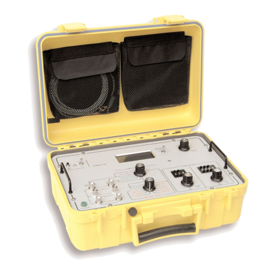
PSD60-2R
FUEL QUANTITY TEST SET
MANUAL NUMBER: E6-0597-00 (75321)
REVISION: A1
DATE: 12/01/2010
WARNING: INFORMATION SUBJECT TO EXPORT CONTROL LAWS
This document contains controlled technology or technical data under the jurisdiction of the Export Administration
Regulations (EAR), 15 CFR 730-774. It cannot be transferred to any foreign third party without the specific prior
approval of the U.S. Department of Commerce Bureau of Industry and Security (BIS). Violations of these
regulations are punishable by fine, imprisonment, or both.
This document is proprietary to Aeroflex,
and is not to be reproduced or otherwise disseminated without the written consent of Aeroflex.
14408 West 105th Street – Lenexa, KS – 66215-2316
Telephone: (800) 237-2831 / (913) 693-1700 Fax: (913) 324-3103
www.aeroflex.com
Advertisement
Table of Contents

Related Manuals for Aeroflex PSD60-2R


Summary of Contents for Aeroflex PSD60-2R
- Page 1 This document is proprietary to Aeroflex, and is not to be reproduced or otherwise disseminated without the written consent of Aeroflex. 14408 West 105th Street – Lenexa, KS – 66215-2316 Telephone: (800) 237-2831 / (913) 693-1700 Fax: (913) 324-3103...
- Page 2 Aeroflex Wichita, Inc. • 14408 West 105 Street • Lenexa • KS 66215-2316 • USA Tel: +1 (913) 693 1700 • Fax: + 1 (913) 324 3103 • www.aeroflex.com 05-0035-00 Rev 05...
- Page 3 Three-phase alternating current. This symbol indicates that the equipment requires 3-phase ac input. Earth (ground) terminal. This symbol indicates the ground (earth) terminal. SAFETY AND REGULATORY INFORMATION PSD60-2R - REV. 1 – JANUARY 5, 2006 – PAGE 1...
- Page 4 Out-position of a bistable push control. This symbol indicates the out (off) position of a bistable push control. CE Mark. ™ of the European Community. SAFETY AND REGULATORY INFORMATION PSD60-2R - REV. 1 – JANUARY 5, 2006 – PAGE 2...
- Page 5 ESD wrist strap with cord (JPN 90-0283-02), or equivalent, must be used at all times when operating this unit. See the manufacturer’s instructions that come with each package for proper connection and use. SAFETY AND REGULATORY INFORMATION PSD60-2R - REV. 1 – JANUARY 5, 2006 – PAGE 3...
- Page 6 Aeroflex Maintenance Manual REVISION HISTORY – PSD60-2R MAINTENANCE MANUAL E6-0597-00 / 10000015088 / 75321 06-0597-00 / 10000015089 / 3357 Revision Date Reason Reference 04/07/09 Update drawings J38229 09/30/09 Update dwgs change address J39558 09/30/10 Add 2-wire / 3-wire switch, update dwgs...
- Page 7 REVISION: A1 – December 1, 2010 REV. REV. DRAWING NO. LEVEL DRAWING NO. LEVEL Safety and Regulatory Information Table of Contents Section I Section II Section III DRAWING REVISION HISTORY – PSD60-2R – DECEMBER 1, 2010 – PAGE 1 OF 1...
-
Page 8: Table Of Contents
EQUIPMENT REQUIRED BUT NOT SUPPLIED........SECTION II MAINTENANCE GENERAL MAINTENANCE................ BILLS OF MAT, ASSY DWGS, SCHEMATICS & TEST PROCED.... SECTION III DRAWINGS BILLS OF MAT, ASSY DWGS, SCHEMATICS & TEST PROCED.... PSD60-2R – REV 14 – SEPTEMBER 30, 2010 – PAGE T-1... -
Page 9: Section I
This manual provides maintenance information for the Aeroflex PSD60-2R Fuel Quantity Gauging System Test Set. The PSD60-2R Fuel Quantity Gauging System Test Set is an instrument that permits complete functional checkout and calibration of an AC Fuel Gauging System, on or off the aircraft. The test set can accurately measure the capacitance of Tank Units, Compensators, or entire systems. -
Page 10: Equipment Description
Aeroflex Maintenance Manual 1.2 EQUIPMENT DESCRIPTION Figure 1-1 shows the front panel of the test set. Refer to Table 1-1 for the description and function of each item. FIGURE 1-1 PSD60-2R – REV 14 – SEPTEMBER 30, 2010 – PAGE 1-2... - Page 11 HI-Z line to aircraft FQGs. INDICATOR COMP Allows connection from test set COMP SIMULATOR to aircraft FQGs. TANK UNITS LO-Z Allows connection from test set measurement circuits to aircraft tanks. PSD60-2R – REV 14 – SEPTEMBER 30, 2010 – PAGE 1-3...
- Page 12 C1 and C2 have 180 degree rotation for minimum to maximum value with no stops. It is NOTE: therefore possible to have an increasing value in either the clockwise or counter clockwise direction. TABLE 1-1 PSD60-2R – REV 14 – SEPTEMBER 30, 2010 – PAGE 1-4...
-
Page 13: Unpacking And Inspecting Equipment
0 to 359 Phase Shift. Greater of +/- 0.1% of reading or 2 F Resistance: Greater of 2% of reading or 0.1 ohm +/- 5% of reading for R > 2000 M ohm PSD60-2R – REV 14 – SEPTEMBER 30, 2010 – PAGE 1-5... -
Page 14: Accessories Supplied
Operation Manual, JPN 06-0597-01. 1.6 EQUIPMENT REQUIRED BUT NOT SUPPLIED The following is a list of equipment that is referenced in this manual but not supplied with a PSD60-2R: Aircraft Interface Cabling PSD60-2R – REV 14 – SEPTEMBER 30, 2010 – PAGE 1-6... -
Page 15: Maintenance
2.2 BILLS OF MATERIAL, ASSEMBLY DRAWINGS, SCHEMATICS & TEST PROCEDURE To assist in the maintenance of the PSD60-2R, bills of material, assembly drawings, schematics and a test procedure are included in Section 3 of this manual. PSD60-2R – REV 11 – SEPTEMBER 30, 2009 – PAGE 2-1... - Page 16 DRAWINGS 3.1 BILLS OF MATERIAL, ASSEMBLY DRAWINGS, SCHEMATICS & TEST PROCEDURE To assist in the maintenance of the PSD60-2R; bills of material, assembly drawings, schematics and a test procedure are included in this section of the manual. DRAWING NUMBER DESCRIPTION REVISION Drawing Section 1.
- Page 17 12/01/2010 Display BOM Level by Level Material RevLev Description Plnt Key date PSD60-2R AC CAPACITANCE FUEL QTY 1100 12/01/2010 Alternative Text Base quantity Valid from - to 00020898 1.000 03/18/2009 12/31/9999 Lv Item Component no. SortStrng Quant Valid from - To...
- Page 18 12/01/2010 Display BOM Level by Level Material RevLev Description Plnt Key date PSD60-2R AC CAPACITANCE FUEL QTY 1100 12/01/2010 Alternative Text Base quantity Valid from - to 00020898 1.000 03/18/2009 12/31/9999 Lv Item Component no. SortStrng Quant Valid from - To...
- Page 19 18.000 03/18/2009 - 12/31/9999 BATTERY ALKALINE 1.5V SIZE C 0001 18.000 1 0270 51125 1.000 03/18/2009 - 12/31/9999 FRT PNL PSD60-2R (MOD 4 & UP) 0001 1.000 1 0280 51805 1.000 03/18/2009 - 12/31/9999 BRKT KILL SWIT PSD90-1M 0001 1.000 1 0290 58345 1.000...
- Page 20 2.000 03/18/2009 - 12/31/9999 BATTERY COVER PSD60-2R AC CAP 0001 2.000 1 0370 70927 1.000 03/18/2009 - 12/31/9999 LENS PSD60-2R (MOD 4 & UP) 0001 1.000 1 0380 70963 2.000 03/18/2009 - 12/31/9999 WASHER FLAT 3/8 NYLON .0625 TH 0001 2.000...
- Page 21 12/01/2010 Display BOM Level by Level Material RevLev Description Plnt Key date PSD60-2R AC CAPACITANCE FUEL QTY 1100 12/01/2010 Alternative Text Base quantity Valid from - to 00020898 1.000 03/18/2009 12/31/9999 Lv Item Component no. SortStrng Quant Valid from - To...
- Page 45 09/30/2010 Display BOM Level by Level Material RevLev Description Plnt Key date 18175 PSD60-2R SWITCH BD 1000 09/30/2010 Alternative Text Base quantity Valid from - to 00004120 1.000 07/10/2007 12/31/9999 Lv Item Component no. SortStrng Quant Valid from - To...
- Page 51 09/30/2010 Display BOM Level by Level Material RevLev Description Plnt Key date 58345 CABLE GROUND STRAP 1100 09/30/2010 Alternative Text Base quantity Valid from - to 00012384 1.000 04/14/2009 12/31/9999 Lv Item Component no. SortStrng Quant Valid from - To Description Ict OD Pha Asm...
- Page 53 PSD60-2R TEST PROCEDURE / RECORD Revision History Revision Date Reason Reference 4-12-05 Change sections 2.11 and 3.1 DCO 28747 6-18-07 Removed old logos and references DCO 33111 10-19-07 Change required equipment list to reflect DCO 35728 current equipment. Added data sheet to bottom of procedure.
- Page 54 Mod Status: _____________ PURPOSE This specification defines the procedure to be used for the complete testing of the Aeroflex, PSD60-2R AC CAPACITANCE TESTER with mod 6 or greater. This procedure is to provide an orderly sequence of tests to insure a completely tested system.
- Page 55 PSD60-2R TEST PROCEDURE / RECORD S/N: _____________ Tested By: _____________ Date: _____________ Mod Status: _____________ SECTION A - THIS SECTION TO BE PERFORMED TO TEST UNITS CALIBRATION AND MAY BE RETURNED TO SERVICE ONLY IF ALL TESTS PASS. INTRINSIC SAFETY TESTS ____ 1.1...
- Page 56 PSD60-2R TEST PROCEDURE / RECORD ____ 2.2 With no connections made to the TANK UNITS HI-Z jack, verify the unit displays 0.00 +/- 0.02pF. _______pF. ____ 2.3 Connect the TRANSFER STANDARD (PTS-1) to the unit as follows. TANK UNITS HI-Z to CAP STANDARD HI-Z and TANK UNITS LO-Z to CAP STANDARD LO-Z and set to 180pF.
- Page 57 PSD60-2R TEST PROCEDURE / RECORD 2.10 Set the frequency of the PSD60 to 7500Hz, place the CAPACITANCE MEASUREMENT switch to MODE A and measure the following cap values and verify they are within the given limits as indicated on the standard. Then place the CAPACITANCE MEASUREMENT switch to MODE B...
- Page 58 PSD60-2R TEST PROCEDURE / RECORD MAGNITUDE CAPACITANCE ACCURACY WITH PHASE AT 4800Hz Connect the PTS-1 and PPS-1 to the PSD60. Set the unit and the PPS-1 to a frequency of 4800Hz and place the CAPACITANCE MEASUREMENT MODE switch to MODE B. Set the PPS-1 to the 0...
- Page 59 PSD60-2R TEST PROCEDURE / RECORD SIM CAP VALUE TEST AND AC CAP NULL TEST Set the coarse knob to each of the following capacitances and verify the display indicates that capacitance. Record measurements in the table below. SIMULATOR MEASURED LIMITS COMP 9.9 - 10.1pF...
- Page 60 PSD60-2R TEST PROCEDURE / RECORD Measure the following resistor values and verify they are within the given limits as indicated on the standard. PASS RES VALUE LIMITS STANDARD READING _____ a. 18/22 0.22 ________ ________ _____ b. 180 1.80 ________...
- Page 61 PSD60-2R TEST PROCEDURE / RECORD SECTION B - THIS SECTION TO BE PERFORMED TO ENSURE A COMPLETELY CALIBRATED UNIT CALIBRATION SET UP ____ 1.1 Set S2-4 to the ON position, set the FUNCTION SELECT switch to the MEASURE EXT position, the MEGGER SELECT switch to the TU position, the capacitance measurement mode switch to A and set the frequency to 10 kHz.
- Page 62 PSD60-2R TEST PROCEDURE / RECORD ____ 1.12 Set the Frequency for 5000 Hz and ENTER. Place the FUNCTION switch to MEASURE EXT and the MEGGER SELECT switch to HI-Z/SHIELD. Set the PTS-1 MEGGER SOURCE switch to SHIELD/HI-Z and connect CHASSIS to CHASSIS of the unit.
- Page 63 PSD60-2R TEST PROCEDURE / RECORD AC CAPACITANCE CALIBRATION ____ 1.14 Set the FUNCTION SELECT switch to the MEASURE EXT TU position. Connect TANK UNITS LO-Z jack to the PTS-1 CAP STANDARD LO-Z jack. When needed, connect TANK UNITS HI-Z to the PTS-1 HI-Z jack. Apply the given capacitances to the unit and adjust the FREQUENCY SELECT knob to the capacitances indicated on the PTS-1 correction chart.
- Page 64 PSD60-2R TEST PROCEDURE / RECORD SECTION C - THIS SECTION TO BE PERFORMED TO ALL NEW AND REWORKED UNITS TO ENSURE COMPLETE FUNCTIONALITY MAIN BOARD TESTS ____ 1.1 Remove J12 from the main board and apply the power supply set for 24VDC and limited to 300mA to A1P12-2 (LO) and A1P12-3 (HI).
- Page 65 PSD60-2R TEST PROCEDURE / RECORD REFERENCE VOLTAGE TESTS 1.11 Apply power to unit and verify the following voltages and ripple with respect to TP1. ____ a. TP10 +5.00 +/- 0.05VDC RIPPLE <50mV P to P _______VDC ____ b. TP30 -5.00 +/- 0.10VDC RIPPLE <50mV P to P...
- Page 66 PSD60-2R TEST PROCEDURE / RECORD 1.17 Set the frequency for 1000Hz. LO-Z DETECTOR ____ 1.18 With the voltmeter monitor TP19 (HI) and TP1 (LO) and verify 6.57Vrms +/- 0.3Vrms. _______Vrms ____ 1.19 With the voltmeter monitor TP21 (LO) and TP20 (HI) and verify 1.18VDC +/- 0.06VDC.
- Page 67 PSD60-2R TEST PROCEDURE / RECORD ____ 2.2 Set the SIMULATOR COMP COARSE and SIMULATOR TU COARSE to 0 pF. Adjust C1 to maximum capacitance on the display and verify pointer, on the TU FINE knob, is at MAX. Then adjust TU FINE until the reading is 10.00pF +/- 0.05pF. Set MEGGER SELECT switch to COMP, adjust C2 to the maximum capacitance on the display and verify pointer, on the COMP FINE knob, is at MAX.
- Page 68 PSD60-2R TEST PROCEDURE / RECORD ____ 2.7 Adjust the TU SIMULATOR to each of the following capacitances. Record these measurements, then place the FUNCTION SELECT switch to SIM TU ONLY and verify the AH 2500A indicates the simulated capacitance within the limits given. Only the TU section of the table below will be filled out at this time.
- Page 69 PSD60-2R TEST PROCEDURE / RECORD MEGGER SELECT SWITCH TESTS 2-3 WIRE SWITCH POSITIONS ON APP IF MOD 8 IS INSTALLED. (SKIP 3.3) Note: MEGGER SELECT TESTS Apply power to unit, set to MEASURE EXT mode, place the MEGGER MODE switch to 3-WIRE, and set option switch, S2-2 on the main board, to the ON position.
- Page 70 PSD60-2R TEST PROCEDURE / RECORD ____ 4.3 Set the PTS toggle switch to the DTF position, measure the following cap values and verify they are within the given limits as indicated on the standard: NOTE: Round standard value down to nearest whole number...
- Page 71 PSD60-2R TEST PROCEDURE / RECORD CAP BASIC ACCURACY AT 2400Hz Set the unit to a frequency of 2400Hz. Measure the following cap values and verify they are within the given limits as indicated on the standard. PASS CAP VALUE LIMITS...
- Page 72 PSD60-2R TEST PROCEDURE / RECORD PARALLEL CAPACITANCE ACCURACY WITH PHASE AT 1200Hz Set the unit and the PPS-1 to a frequency of 1200Hz and place the CAPACITANCE MEASUREMENT MODE switch to MODE A. Set the PPS-1 to the 0 angle and record the unit reading in the calculated measurement column.
- Page 73 PSD60-2R TEST PROCEDURE / RECORD MAGNITUDE CAPACITANCE ACCURACY WITH PHASE AT 600Hz Connect the PTS-1 and PPS-1 to the PSD60. Set the unit and the PPS-1 to a frequency of 600Hz and place the CAPACITANCE MEASUREMENT MODE switch to MODE B. Set the PPS-1 to the 0...
- Page 74 PSD60-2R TEST PROCEDURE / RECORD MAGNITUDE CAPACITANCE ACCURACY WITH PHASE AT 9600Hz Connect the PTS-1 and PPS-1 to the PSD60. Set the unit and the PPS-1 to a frequency of 9600Hz and place the CAPACITANCE MEASUREMENT MODE switch to MODE B. Set the PPS-1 to the 0...
- Page 75 PSD60-2R TEST PROCEDURE / RECORD FINAL TESTS ____ 6.1 Insure all internal hardware is installed and secure. ____ 6.2 Perform Section B to calibrate the unit. ____ 6.3 Remove battery cable from MAIN board and power with an external power supply set for 24VDC.
- Page 76 PSD60-2R TEST RECORD AS FOUND AS LEFT PSD60-2R MOD 6 OR GREATER CALIBRATION DATA SHEET S/N: _____ Tested By: _____ Date: _____ Mod Status: _____ INTRINSIC SAFETY TESTS MAX LO-Z DRIVE TEST Verify the ammeter indicates less than 10mA RMS.
- Page 77 PSD60-2R TEST RECORD 2.10 7500Hz MODE A and MODE B Capacitance accuracy table. CAP VALUE LIMITS STANDARD MODE A MODE B PASS READING READING 10pF 0.05pF 180pF 0.10pF 220pF 0.2pF 500pF 0.3pF 900pF 0.5pF 1800pF 1.0pF 2200pF 5000pF 9000pF 18000pF 10pF 39.00KpF...
- Page 78 PSD60-2R TEST RECORD 3.5 cont CAP VALUE PHASE LIMITS MEASURED MODE B PASS ANGLE CAPACITANCE READING 2200pF +/-2pF -------- 30 2200pF +/-2pF -------- 45 2200pF +/-2pF -------- 60 2200pF +/-2pF -------- 75 2200pF +/-2pF -------- 90 18000pF -------- -------- 0...
Need help?
Do you have a question about the PSD60-2R and is the answer not in the manual?
Questions and answers