Advertisement
Quick Links
Download this manual
See also:
Programming Manual
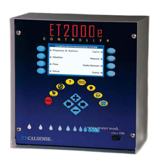
ET2000e IRRIGATION CONTROLLER INSTALLATION
®
ET2000e
IRRIGATION CONTROLLER
INSTALLATION
CHANGE 1
12 March 2007
water work
m aking
since 1986
Advertisement

Summary of Contents for Calsense ET2000e
- Page 1 ET2000e IRRIGATION CONTROLLER INSTALLATION ® ET2000e IRRIGATION CONTROLLER INSTALLATION CHANGE 1 12 March 2007 water work m aking since 1986...
-
Page 2: Controller Installation
• The pedestal is to be mounted on a level concrete base with the top of the base at Calsense Irrigation Controllers are supplied by low least 2 inches above grade. This base voltage 24 VAC step-down transformers. The should be about 6 ½ inches by 12 inches by irrigation controller and transformer are housed in a 11 inched deep. - Page 3 ET2000e IRRIGATION CONTROLLER INSTALLATION ® TPP Transient Protection Package Mounting Sheet CHANGE 1 12 March 2007 water work m aking since 1986...
- Page 4 ET2000e IRRIGATION CONTROLLER INSTALLATION ® PD-1 Pedestal Mounting Sheet CHANGE 1 12 March 2007 water work m aking since 1986...
- Page 5 ET2000e IRRIGATION CONTROLLER INSTALLATION ® PD-1 Pedestal Mounting Sheet (Continued) CHANGE 1 12 March 2007 water work m aking since 1986...
- Page 6 ET2000e IRRIGATION CONTROLLER INSTALLATION ® SSE / SSE-R Pedestal Mounting Sheet CHANGE 1 12 March 2007 water work m aking since 1986...
- Page 7 ET2000e IRRIGATION CONTROLLER INSTALLATION ® SSE / SSE-R Pedestal Mounting Sheet (continued) CHANGE 1 12 March 2007 water work m aking since 1986...
- Page 8 ET2000e IRRIGATION CONTROLLER INSTALLATION ® SSE-D / SSE-D-R Pedestal Mounting Sheet CHANGE 1 12 March 2007 water work m aking since 1986...
- Page 9 ET2000e IRRIGATION CONTROLLER INSTALLATION ® SSE-D / SSE-D-R Pedestal Mounting Sheet (continued) CHANGE 1 12 March 2007 water work m aking since 1986...
- Page 10 ET2000e IRRIGATION CONTROLLER INSTALLATION ® CHANGE 1 12 March 2007 water work m aking since 1986...
- Page 11 ET2000e IRRIGATION CONTROLLER INSTALLATION ® Electrical Hookup 120 VAC Power Connections and Unit Grounding Station Wire Connections Perform all 120 VAC electrical and grounding CAUTION: hookup per local and national electric code. NEVER touch station wires and field wires together •...
-
Page 12: Power Consumption
For the -LR option on ET2000 Controllers consumption for their solenoid. use 3.4 W, for ET2000e use the table value. Additional Notes: This value is considered typical for an 1) The numbers in the table represent average irrigation valve. The actual valves in use may be power consumption as if it didn’t fluctuate during... - Page 13 When a mainline break is detected the • The master valve wire from the irrigation Calsense system will terminate all irrigation and controller provides a 24 VAC output to the take the required action to close the master master valve. Connect the master valve wire valve.
- Page 14 DO NOT When connecting a Remote control interface cable, install the rain cup in this manner with Calsense use the same station wires and common as irrigation controllers because it will disable some of connected to the field wires.
- Page 15 ET2000e IRRIGATION CONTROLLER INSTALLATION ® Grounding Instructions WARNING: NON-LIGHTNING PRONE AREAS Never connect the ground rod or the white wire (field common) to the Black wire (Flow return) of Stand Alone System: the black wiring harness. This will disable the over current protection, and could result in damage to •...
- Page 16 ET2000e IRRIGATION CONTROLLER INSTALLATION ® Grounding Instructions Diagram CHANGE 1 12 March 2007 water work m aking since 1986...
- Page 17 ADDITIONAL IRRIGATION CONTROLLER OPTIONS Multiple Flow Meter Interface (-F option) Calsense ET2000e Irrigation Controllers can receive up to three (3) separate flow inputs and (3) separate Master Valve inputs with projects consisting of more than one water source for irrigation landscape. However the irrigation controller must be specified with the –F option.
- Page 18 (LA-2) pigtail and the - M irrigation controller pigtail to one of the terminals labeled FIELD COMMON on the board. Connect the yellow wire from both line amplifier and - M pigtails to the terminal labeled SHIELD. Note: Older controllers may require a different wiring diagram, contact Calsense at 1-(800)-572-8608 for more information.
- Page 19 ET2000e IRRIGATION CONTROLLER INSTALLATION ® CENTRAL COMMUNICATION Non-Hardwired- -to Hardwired Communication (-M-LR, -M-CR, -M-SR, -M-EN, -M-WEN, -M-GR, M-FOM, to a - M option) Several irrigation controllers can share one Communications device. The irrigation controller which has the communications device is designated with a –M plus the two letter communications option. The Communications device is powered by the controller panel.
- Page 20 ET2000e IRRIGATION CONTROLLER INSTALLATION ® STATION COLOR WIRE CODE CHANGE 1 12 March 2007 water work m aking since 1986...
- Page 21 ET2000e IRRIGATION CONTROLLER INSTALLATION ® MODEL ET2000e Wiring Diagram CHANGE 1 12 March 2007 water work m aking since 1986...
- Page 22 Note 2: 12 controller maximum only if using the (-M) option only on all controllers in a chain. Note 3: One Moisture sensor per four (4) active valves recommended. Note 4: Antenna type: 1. LR-HUB 150 feet LMR-400-DB cable, if further contact Calsense communications technician. 2. LR-RR-DOME 50 feet maximum LMR-400-DB cable.
- Page 23 ET2000e IRRIGATION CONTROLLER INSTALLATION ® CONTROLLER & FIELD WIRING DISTANCE CHART CHANGE 1 12 March 2007 water work m aking since 1986...
- Page 24 ET2000e IRRIGATION CONTROLLER INSTALLATION ® ® 2075 Corte del Nogal, Suite P, Carlsbad CA 92011 1-(800)-572-8608 FAX: 1-(760)-438-2619 www.calsense.com Stock Number: PG4-IC-C Rev. 03/07 CHANGE 1 12 March 2007 water work m aking since 1986...


Need help?
Do you have a question about the ET2000e and is the answer not in the manual?
Questions and answers