
Related Manuals for Ohkura RM10C


Summary of Contents for Ohkura RM10C
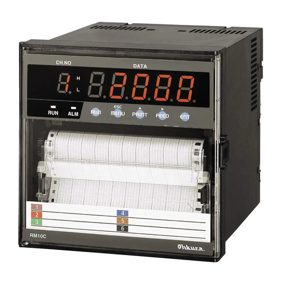
- Page 1 RM10C HYBRID RECORDER COMMUNICATION COMMAND INSTRUCTION MANUAL HXPRM10mnC0005E Jan. 2016 (2nd Edition) All Rights Reserved, Copyright © 2004-2016, Ohkura Electric Co., Ltd. ― ― HXPRM10mnC0005E...
- Page 2 For safety using Thank you for purchasing our RM10C Hybrid Recorder. In order to this instrument to exhibit all of its functions effectively and correctly, read and understand this instruction manual thoroughly before using the instrument. The symbols below are used on this instrument for the cautioning information.
- Page 3 CAUTION Input and Output Wiring Do not use empty terminals for other purposes such as relaying, etc. When transporting this instrument or the equipment with this instrument Transportation incorporated in it, take measures to prevent opening the door and falling out the inner module.
- Page 4 2.Guide of Instruction manual The instruction manuals of this instrument are as the table below. Name Part No. Outline Explanation for installing, wiring, RM10C Hybrid Recorder HXPRM10mnC0001E standard operation. And setting instruction manual HXPRM10mnC0002E or operation for using this instrument.
-
Page 5: Table Of Contents
CONTENTS 1. INTRODUCTION ......................... 5 1.1 General Description ......................5 1.2 Difference in RS-485, RS-232C ................... 5 1.3 Original Protocol - Basic item about the command .............. 5 1.4 Basic item about the Modbus RTU protocol ................. 6 2. ORIGINAL PROTOCOL - THE RECEPTION OF THE DATA ............. 7 2.1 Setup command ........................ -
Page 6: Introduction
1. INTRODUCTION 1.1 General Description This instruction manual describes the communication command of the RM10C Recorder. Please refer to the instruction manual (HXPRM10mnC0001E, HXPRM10mnC0002E) for the transmission of the measurement data, a setup of communication and wiring. Wiring and Request... -
Page 7: Basic Item About The Modbus Rtu Protocol
1.4 Basic item about the Modbus RTU protocol Modbus protocol is a Modicon Inc. (AEG Schneider Automation International SAS) is a communication protocol that was developed for the PLC, are listed in the protocol specification (PI-MBUS-300 Rev.J). Please refer to the same specification for the specification of the Modbus protocol. In this manual, we describe the function code and data content of mainly Modbus protocol that can be used in the present equipment. -
Page 8: Original Protocol - The Reception Of The Data
2. ORIGINAL PROTOCOL - THE RECEPTION OF THE DATA 2.1 Setup command 2.1.1 Setup command list Table 2.1 Setup command list Command Setting item The number of Contents of a parameter the parameters SR Setting the range MAX 7 Channel,Mode,Range(Reference Channel) Span lower limit value. -
Page 9: Setting Of Input Range/Record Span
2.1.2 Setting of INPUT RANGE/RECORD SPAN The input range and record span of each channel is set up as follows. <Format> SR(CH),(Mode),(Pr1),(Pr2),(Pr3),(Pr4),(Pr5),(Pr6),(Pr7)(CR)(LF) CH: Specify the channel number to set. Mode: The input mode is set up. : The number of Pr varies depend on the contents of Mode. - Page 10 (4) The setting of Scaling. CH:Setting Channel 01~06(The pen type is 01~02.). Mode:SCL Pr1:VOLT, TC, RTD Pr2:Scaling Mode Pr3:Left End(Zero Input Value) Refer to table 2.2. Pr4:Right End(Span Input Value) Pr5:Scaling Left End Pr6:Scaling Right End Pr7: Decimal point position(0~4) Example)SR04,SCL,RTD,PT,0,3000,0,30000,2(CR)(LF) [CAUTION] [CAUTION]...
- Page 11 Table 2.2 Setting range Input Range or Zero Input Span Input Decimal Note Range Scaling Value Value Point Mode (Left End) (Right End) (Fixation) VOLT ±10mV 10mV -1000 1000 0~20mV 20mV 2000 0~50mV 50mV 5000 ±200mV 200mV -2000 2000 ±1V -1000 1000 0~5V...
-
Page 12: Setting Of Alarm
2.1.3 Setting of Alarm The Alarm of each channel is set up as follows. <Format> SA(CH),(LEVEL),(ON/OFF),(TYPE),(VALUE),(RLY ON/OFF),(RLY No.)(CR)(LF) Item Contents Setting Range Note Channel number 01~06(multi) 01~02(pen) LEVEL Alarm Level 1~4 ON/OFF ON or OFF It can be omitted. Alarm ON/OFF TYPE Alarm Type It can be omitted. -
Page 13: Setting Of The Date/Time
2.1.6 Setting of the date/time The date/time of the internal watch of the recorder is set up as follows. <Format> SD(DATE),(TIME)(CR)(LF) DATE:YY/MM/DD (YY)Year 00~99 (MM)Month 01~12 (DD)Day 01~31 TIME:HH:MM:SS (HH)Hour 00~23 (MM)Minute 00~59 (SS)Second 00~59 2.1.7 Copying the Setting Data of the channel The setup data of the channel can be copied on other channels. -
Page 14: Setting Of The Partial Compression/Expansion
2.1.10 Setting of the Partial Compression/Expansion The Partial Compression/Expansion recording of each channel is set up as follows. <Format> SP(CH),(ON/OFF),(BOUNDARY POSITION),(BOUNDARY VALUE)(CR)(LF) CH:Setting Channel 01~06(The Pen type is 01~02.). ON/OFF:Partial Compression/Expansion function ON or OFF BOUNDARY POSITION: 1~99% BOUNDARY VALUE: CH is VOLT,TC,RTD,DELT,SIGM or MEAN mode: In the span data CH is SCALE,SQRT,DECAD mode: In the scale data Part of underline can be omitted. -
Page 15: Setting Of The Comment Character
2.1.13 Setting of the Comment Character The Comment Character to print by the Digital Input is set up. <Format> SG(Cn),(COMMENT)(CR)(LF) Cn:Comment Number(1~3) COMMENT:A Comment Character is set up with the character code shown by the table 2.3. (Multipoint type is within 16 characters. Pen type is within 12 characters.) When you use the character code beyond 7F , the data length of communication function must be used as 8 bit. -
Page 16: Control Command
2.2 Control command 2.2.1 Control command list Table 2.4 Control command list Command Control Item The number of The explanation of operation parameter PS0 - Recording Start This command is the same as RUN key. PS1 - Recording Stop MP0 -... -
Page 17: Recording Start/Stop
2.2.2 Recording Start/Stop This command starts or stops recording of the recorder. <Format> PS0(CR)(LF) ・・・The recorder starts the record. PS1(CR)(LF) ・・・The recorder stops the record. 2.2.3 Manual Print Start/Stop This command starts or stops printing of the "Manual print". <Format> MP0(CR)(LF)... -
Page 18: Choice Of The Display Contents
2.2.6 Choice of the display contents. This command chooses the display mode of the recorder. The Auto Display, the Manual Display, the Date Display, the Time Display and Display OFF can be chosen. When receiving this command, the display of recorder changes automatically. <Format>... -
Page 19: Original Protocol - Data Transmission
3. ORIGINAL PROTOCOL - DATA TRANSMISSION 3.1 Getting the Set Value When the recorder receives "(TS1)+(ESC T)+(LF)", the recorder sends the setting value continuously according to the following table 3.1. The output formats of each command are as same as that of format when it set up. Table 3.1 Order of the set value transmission Command... -
Page 20: Original Protocol - Notes Of Communication
4. ORIGINAL PROTOCOL - NOTES OF COMMUNICATION 4.1 Half-Duplex Transmission The recorder side is the half-duplex transmission. The recorder cannot receive the data while sending the data. When the host computer sends the next data, all the receiving data must be completed. 4.2 Multiple access Don't open another recorder when one recorder is opened on the same line. -
Page 21: Modbus Rtu Protocol - Overview
5. Modbus RTU PROTOCOL - OVERVIEW 5.1 Modbus RTU Protocol Item Specification Interface RS-485/RS-232C Protocol Modbus RTU Communication speed 1200 /2400 /4800 /9600 /19200/ 38400 [bps] Parity None/Even/Odd Data length 8bit(※) Stop bit 1bit / 2bit Slave address 1~247(0 invalid) ※... -
Page 22: Modbus Rtu Protocol - Data Transmission And Reception
Modbus RTU PROTOCOL - DATA TRANSMISSION AND RECEPTION 6.1 Communication Protocol This equipment is compatible with Modbus RTU protocol. Data format of the protocol is as below. It is composed of slave address, function code, data, and CRC section. Modbus RTU Data format Slave address Function code Data... -
Page 23: Reading Of Input Register Area
6.4 Reading of input register area The input register area is a read-only area. The current measured value and the current time are mapped. Specify the start address (relative) and data count (assuming that one word is two bytes) of the data to be read. 6.4.1 Reading of input register area Function code :04H ■... -
Page 24: Input Register Area Map
6.4.2 Input Register Area Map 【Input Register Area Map】Function code: 04H Relative Address address Name Array Content Remarks (HEX) :"MULTI" Model type(1/8) Multipoint type ASCII 30001 :"PEN" Model type(2/8) Pen type 30002 Model type(3/8) After the blank 30003 Model type(4/8) 30004 Model type(5/8)... - Page 25 Relative Address address Name Array Content Remarks (HEX) Reserve 30050 0~99 Year 30051 Every second update 1~12 Month 30052 1~31 30053 0~24 Hour 30054 0~59 Minute 30055 0~59 Second 30056 0:Recording not in progress 0~1 1:Recording in progress Recording status 30057 0:With chart 0~1...
- Page 26 Relative Address address Name Array Content Remarks (HEX) Current unit Unit (1/4) 30131 Unit (2/4) 30132 CH01 Unit (3/4) 30133 Unit (4/4) 30134 Current unit Unit (1/4) 30135 Unit (2/4) 30136 CH02 Unit (3/4) 30137 Unit (4/4) 30138 Current unit Unit (1/4) 30139 Unit (2/4)
-
Page 27: Reading And Writing Of The Holding Register Area
6.5 Reading and writing of the holding register area The holding register area is a read-write area. Parameter settings and the start and stop command of the recording state are mapped. For read, specify the start address (relative) and data count (assuming that one word is two bytes) of the data to be read. -
Page 28: Writing Of The Holding Register Area (Single)
6.5.2 Writing of the holding register area (Single) It is used when carrying out a set of command operations or parameters. In the case of operation command, it will take effect immediately when you send. In the case of parameter settings, it is reflected by sending a separate "settings save" command (address 40104 (relative address 0067H)). -
Page 29: Writing Of The Holding Register Area (Continuation)
6.5.3 Writing of the holding register area (Continuation) Time setting command and the like, and then used when the data needs to send in succession. In the case of operation command, it will take effect immediately when you send. In the case of parameter settings, it is reflected by sending a separate "settings save" command (address 40104 (relative address 0067H)). -
Page 30: Holding Register Area Map
6.5.4 Holding register area map 【Holding register area map】Fanction Code:03H(Reading),06H(Writing),10H(Continuous writing) Relative Address address Name Array Content Remarks (HEX) 40001 0 Reserve Unused … 40100 63 Reserve Operation command 40101 64 Recording start / stop Invalid except left. AA01:Start The disabled in selecting DI. AA00:Stop 40102 65 Reserve... - Page 31 【Holding register area map】Fanction Code:03H(Reading),06H(Writing),10H(Continuous writing) Relative Address address Name Array Content Remarks (HEX) 40140 Printing character (18/) 40141 Printing character (19/) 40142 Printing character (20/) 40143 Printing character (21/) 40144 Printing character (22/) 40145 Printing character (23/) 40146 Printing character(24/24) 40147 Reserve …...
- Page 32 【Holding register area map】Fanction Code:03H(Reading),06H(Writing),10H(Continuous writing) Relative Address address Name Array Content Remarks (HEX) 40223 Alarm 1 action ON/OFF 0~1 0:OFF 1:ON 40224 Alarm 1 type 0~1 0:H 1:L -32000~32000 (※3) Depends on the Scaling 40225 Alarm Set value 40226 Alarm 1 RLY output 0~1 0:OFF...
- Page 33 【Holding register area map】Fanction Code:03H(Reading),06H(Writing),10H(Continuous writing) Relative Address address Name Array Content Remarks (HEX) 40263 106 Reserve CH01 … 40300 12B Reserve 40301 12C Mode CH02 Input channel … 40400 18F Reserve 40401 190 Mode CH03 Input channel … 40500 1F3 Reserve 40501 1F4 Mode...
- Page 34 【Holding register area map】Fanction Code:03H(Reading),06H(Writing),10H(Continuous writing) Relative Address address Name Array Content Remarks (HEX) Multipoint type:0~8 Words 40825 338 Comment (1/8) Cmt3 ASCII Pen type:0~6 Words 40826 339 Comment (2/8) 40827 33A Comment (3/8) 40828 33B Comment (4/8) 40829 33C Comment (5/8) 40830 33D Comment (6/8) 40831...
- Page 35 【Holding register area map】Fanction Code:03H(Reading),06H(Writing),10H(Continuous writing) Relative Address address Name Array Content Remarks (HEX) 40965 3C4 Logging print ON/OFF 0~1 0:OFF 1:ON (※7) Logging print interval 40966 3C5 Logging print interval 0~11 40967 3C6 Logging print reference 0~23 Unit:Hour time 40968 3C7 Logging print criteria 0~59 Unit:Minute...
-
Page 36: Holding Register Area Setting Range Detail
6.5.5 Holding register area setting range detail Setting range of register on the map written in the ※ are listed below. ※1 Mode Value Content Remarks Scaling OFF Scaling ON Square root It can be set only when the range code is 0 to 7 (voltage current calculation (SQRT) range). - Page 37 ※3 Depends on the Scaling Scaling range, the alarm set value, partial compression boundary point measurement is depends on the holding register address 40201 "mode" and 40208 "decimal point position". The set value is reflected in the form that is dependent on the "decimal point position" if the mode is scaling ON ( “SCALE”...
- Page 38 ※6 Printing color Value Content Remarks Purple Green Blue Brown Black ※7 Logging print interval Value Content Remarks 10min 15min 20min 30min ※8 DI function Value Content Remarks OFF(No function) RCD(Recording Start/Stop) ON:RUN OFF:STOP SPEED(Chart speed change) ON:Spd-1 OFF:Spd-2 CMNT1(Comment print (Sync)) ON Rising:Start CMNT2(Comment print (Sync)) CMNT3(Comment print (Sync))
Need help?
Do you have a question about the RM10C and is the answer not in the manual?
Questions and answers