
Related Manuals for Ohkura RM10C


Summary of Contents for Ohkura RM10C
- Page 1 RM10C HYBRID RECORDER (MULTIPOINT TYPE RECORDER) INSTRUCTION MANUAL HXPRM10mnC0001E NOV. 2015 (5th Edition) Copyright © 2000-2015 Ohkura Electric Co., Ltd. All Rights Reserved.
- Page 2 For safety using Thank you for purchasing our RM10C Hybrid Recorder. In order to this instrument to exhibit all of its functions effectively and correctly, read and understand this instruction manual thoroughly before using the instrument. Don't use this product in any method not specification by manufacturer. The protective features of this product may be impaired if it is used in a method not specified in the operation manual.
- Page 3 (2) Do not put your foot on the installed instrument or get on it, because it is dangerous. Maintenance Only our serviceman or persons authorized by OHKURA are allowed to remove and take the inner module, the main unit and PRINTed circuit boards apart. Disposal (1) Dispose the replaced batteries in a correct way.
- Page 4 2.Guide of Instruction manual The instruction manuals of this instrument are as the table below. Name Part No. Outline Explanation for installing, wiring, RM10C Hybrid Recorder standard operation. And setting (Multipoint type Recorder) HXPRM10mnC0001E This or operation for using this...
-
Page 5: Table Of Contents
CONTENTS 1. INTRODUCTION ..............6 7. DEVICE SETTING ..............42 1.1 Checking the Accessories ............6 7.1 Setting the Setup Mode .............. 42 1.2 Checking the Type and Specifications ......... 7 7.1.1 Setting the Range ..............45 1.3 Temporary Storage ............... 8 (1) Setting method .............. - Page 6 8. COMMUNICATIONS ............85 10. TROUBLESHOOTING ........... 102 8.1 General Description ..............85 10.1 Troubleshooting ..............102 8.1.1 General Description of Functions ......... 85 10.1.1 Trouble Items ..............102 8.1.2 Transmission Specifications ..........85 10.1.2 When the Recorder Dose not Work at All ....102 8.2 Original Protocol ................
-
Page 7: Introduction
1. INTRODUCTION 1.1 Checking the Accessories Upon delivery of this instrument, unpack and check its accessories and appearance. If there are any missing accessories or damages on the appearance, contact our dealer where you purchased the instrument, or our sales representative. Following accessories should be attached. -
Page 8: Checking The Type And Specifications
1.2 Checking the Type and Specifications A nameplate is affixed to the inside of the instrument. Remove the chart holder and make sure that the nameplate is affixed to the middle far side of the instrument. Make sure that this instrument meets your requested specification, seeing the following tables. Table 1.2 Type 1... -
Page 9: Temporary Storage
1.3 Temporary Storage Store the instrument in the following environment. When incorporated in the equipment, store it in the following environment as well. CAUTION Storage in a poor environment may damage the appearance, functions, and service life of the instrument. Storage Environment ・A place with little dust. -
Page 10: Construction
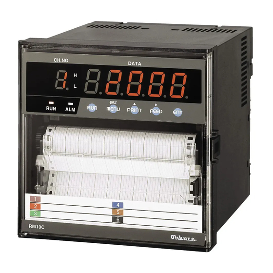
2. CONSTRUCTION 2.1 Appearance Door Case Ribbon cassette Display keyboard Indication card Chart holder Printer Mounting bracket Terminal block Fig. 2.1 Appearance ―9― HXPRM10mnC0001E... -
Page 11: Display Screen And Operation Keys
2.2 Display Screen and Operation Keys 2.2.1 Display Screen The following describes the display screen. Since the channel numbers and data are indicated by a 7-segment LED, alphabets are symbolized to represent them. For the LED display, see " Symbolized Alphabets for Display" at [Reference] below. Alarm Type Display Indicates an alarm type in red. -
Page 12: Operation Keys
2.2.2 Operation Keys The following describes each operation key. This manual represents the actual operation keys as shown in the figure below. CH. No. DATA ▲ MENU PRINT FEED FEED PRINT MENU Fig. 2.3 Actual Display and Operation Keys Table 2.1 Names of Operation Keys and Their Functions Name Function Starts/stops recording. -
Page 13: Installation
3. INSTALLATION 3.1 Outside Dimensions Drawing and Panel Cutting Dimensions Unit: mm <Front> <Rear> CH,NO. DATA (100) MENU PRINT FEED Dimension required when the door is fully opened (135゜). (Wall on the left side). (56) <Side> <Panel Cutting> 200 min. 7 max. -
Page 14: Mounting To The Panel
3.2 Mounting to the Panel WARNING Do not install the instrument in a place exposed to a combustible, explosive, or corrosive gas (SO etc.). CAUTION Install the instrument in the following places ・A place free from where humidity often changes. ・A place of normal temperature (25℃... -
Page 15: Mounting To The Panel In Compliance With The Ip65
Panel Mounting bracket Screw Fig. 3.3 Mounting to the Panel 3.2.2 Mounting to the Panel in compliance with the IP65 Prior to mounting the instrument to the panel, attach a packing to the position shown in the figure. The rest of the procedure is the same. Panel Packing Mounting of Packing... -
Page 16: Wiring
4. WIRING 4.1 Terminal Layout and Power Wiring 4.1.1 Terminal Layout Power source terminal block Communication 6 Relay outputs terminal block (RS-485) 3DI terminal block Input terminal block Communication terminal block (RS-232C) Fig. 4.1 Terminal Layout (Rear view) 4.1.2 Power Wiring WARNING ①... -
Page 17: Wiring Procedure
CAUTION ① As an electric wire for the power source, use a 600 V vinyl insulated wire (IEC60227-3) or its equivalent or above. ② Attach a round press-fitting terminal with insulated sleeve (for M3.5) to the end of the electric wire. ③... -
Page 18: Input Wiring
4.2 Input Wiring CAUTION ①Precautions for the input electric wire See that no noise is mixed in input wiring. For input wiring, it is recommended to use a shielding wire or twisted wire effective for noise. In case of thermocouple input, connect a thermocouple wire directly or use a compensating lead wire. -
Page 19: Wiring Procedure
4.2.1 Wiring Procedure CAUTION The transparent protective cover should surely remove the left and right (both sides) hooks simultaneously. If it removes by turns, there is a possibility that it may damage. 4channel 5channel 6channel 1channel 2channel 3channel DC Voltage Thermocouple DC Current Fig. - Page 20 ① RTD input ② mA input Shunt registor + - Fig. 4.5 Input Wiring ( RTD,mA ) CAUTION ① Attach the shunt resistor to the input terminal block of the instrument. ② Input accuracy is effected with the shunt resistor. Use the following recommended resistor.
-
Page 21: Di/Alarm Output Wiring (Option)
4.3 DI/Alarm Output Wiring (Option) WARNING ① Be sure to wire after turning off the POWER. ② When the power source has been connected to the Alarm output, turn off that power source. ③ When a hazardous voltage supplies to alarm terminal: a)... -
Page 22: Alarm Output Wiring Procedure
CAUTION ① The DI (Option) consists of a combination of 3 Digital inputs. The alarm output consists of 6-Relay output (Normally open). ② Relay No.1 is a common output of paper empty sensor (Option) and alarm. 4.3.2 Alarm Output Wiring Procedure Wire the Alarm output refer to Fig.4.8. -
Page 23: Communication Wiring
4.4 Communication Wiring CAUTION Precautions for the communication wiring ① See that no noise is mixed in communication wiring. For communication wiring, it is recommended to use a shielding wire effective for noise. ② When it is likely to be affected by induction noise, particularly when wiring near the high-frequency power source, it is recommended to use a shielded twisted wire. -
Page 24: Preparations For Operation
5. PREPARATIONS FOR OPERATION 5.1 Setting the Chart Paper CAUTION It is recommended to use our original chart paper to ensure proper recording. If the chart paper holder is taken out with recording operation being activated, the ink ribbon may be damaged. To replace the chart paper, be sure to press the “RUN”... - Page 25 (3) Taking out the Chart Holder Put your fingers onto the levers at both sides of the chart holder and pull it out to this side. Lever Pull out the chart holder to this side. Fig. 5.3 Taking out the Chart Holder (4) Opening the Chart Cover and Chart Guide Open the chart guide and the chart cover outwardly.
- Page 26 (5) Loosening the chart paper The chart paper may not be proper fed, if it is stuck at perforations. Be sure to loosen the paper. Fig. 5.5 Loosening the Chart Paper (6) Setting the Chart Paper into the Storage Chamber Unfold the chart paper by two plies.
- Page 27 (7) Aligning the Chart Paper with the Sprocket Drum Align the holes in the chart paper with the sprocket drum teeth. Set the chart paper along the sprocket drum. Put the first ply of the chart paper into the chart receiver. Make the left and right holes parallel with each other.
- Page 28 (9) Turning the Sprocket Drum Gear Check paper feed with your hand. Turn the sprocket drum gear to feed out the chart paper. (It is recommended to feed the chart paper by 4 plies.) Turn the gear at the left end of the sprocket drum in the arrow direction.
- Page 29 (11) Close the Door Close the door and check a door lock. (12) Pressing the “FEED” key to Check Paper Feed Press the “FEED” key on the display keyboard to feed the chart paper. CH.No DATA ESC ▲ RUN MENU PRINT...
-
Page 30: Setting The Ribbon Cassette
5.2 Setting the Ribbon Cassette CAUTION If the chart holder is taken out with recording operation being activated, the ink ribbon may be damaged. To replace the ribbon cassette, be sure to press the “RUN” key to stop recording. If the ribbon cassette is not set properly, the recording color may change or the ribbon may be damaged. - Page 31 (4) Unslacking the Ink Ribbon Set the new ink ribbon. Turn the knob in the arrow direction to unslack the ink ribbon. Turn the knob in the arrow direction. Knob Slackness Fig. 5.13 Unslacking the Ink Ribbon (5) Setting the Ribbon Cassette Push the ribbon cassette into the ribbon holder until the latch clicks.
-
Page 32: Operation
6. OPERATION 6.1 Operation WARNING Prior to turning on the power, make sure that the supply voltage meets the specifications for the instrument and the instrument is properly grounded. CAUTION Prior to turning on the power, make sure that the chart paper is set in the chart holder. If the printer is activated with no chart paper set, the sprocket drum (cylindrical part) of the chart holder may be damaged. -
Page 33: Recording
6.2 Recording CAUTION ① The instrument checks zero point for every recording. If the printer block is manually moved during recording, a recording position may be dislocated. ② In order to protect the chart paper, dot printing is not performed when the distance between the previous dot printing position and the next one for an identical channel is less than 0.4 ㎜... -
Page 34: Print Sample
RM10C stores up to six items of Alarm Occurrence/Recovery print and five items of Comment/Date-and- Time/Record Start/Record end print. If printing commands are over, RM10C prints a marking "*" on the end of the last printing. This mark is meaning of that over items would not be printed. -
Page 35: Digital Print
6.4 Digital Print The following digital prints operate by the key operation: Manual print List print Engineering list print Run Start/End print The following digital prints operate by the DI input: DI Manual print DI Date/Time print DI Comment print [Reference] Printing is actuated in following priority. -
Page 36: List Print
(2) Manual print stopping procedure ① Press the “PRINT” key. ② Use the “PRINT” key to display “ ” , and press the “ENT” key. ③ Use the “PRINT” key to select “ ” . Pressing the “ENT” key stops manual print. However, print operation continues until the line is completed. - Page 37 (2) List print stopping procedure ① Press the “PRINT” key. ② Use the “PRINT” key to display “ ”, and press the “ENT” key. ③ Use the “PRINT” key to select “ ” . Pressing the “ENT” key stops list print. However, print operation continues until the line is completed.
-
Page 38: Engineering List Print
6.4.3 Engineering List Print Engineering list print provides the following setting data of the instrument on the chart paper. Analog recording Digital printing Burnout/RJC etc. (1) Engineering list print operating procedure ① Press the “MENU” key. ② Use the “PRINT” key to display “ ”, and press the “ENT”... - Page 39 (2) Engineering list print stopping procedure ① Press the “MENU” key. ② Use the “PRINT” key to display “ , and press the “ENT” key. ③ Use the “PRINT” key to select “ . Pressing the “ENT” key stops engineering list print. However, print operation continues until the line is completed.
-
Page 40: Record Start/End Print
6.4.4 Record Start/End Print Record Start/End print the beginning (or ending) time on the chart paper when beginning (or ending) to record. Record Start/End operation is set in the engineering mode. (Refer to 7.2.6 "Record start/end print" ) " " ·········· Record start print is synchronous print. Record end print is asynchronous print. -
Page 41: Di Comment Print
6.4.7 DI Comment Print (option) DI Comment print prints time and comment on paper by turning on DI. The content of comment is set to the setup mode. (1)"DI function" of the engineering mode is set. Please refer to 7.2.9 " DI Functions " for details. "... -
Page 42: Changing The Display
6.5 Changing the Display Display selection procedure ① Press the “MENU” key to display " ", and press the “ENT” key. ② Use the “PRINT” key to select a required display screen from the menu below. Press the “ENT” key. ③... -
Page 43: Device Setting
7. DEVICE SETTING 7.1 Setting the Setup Mode Key Operation for Entering the Setup Mode Press the “MENU” key for 3 seconds or more to enter the setup mode. At the time, displays the version of the software approximately 1 seconds as below. After, displays the setting screen of the range. - Page 44 7.1.3 Setting the Unit Setting Channel Char. No. Code No. (゜) ・ ・ ・ ・ 7.1.4 Setting the Chart Speed Setting 1st/2nd Chart speed Chart speed 7.1.5 Setting the Date and Time Setting Year Month, Day Time ...
- Page 45 Table 7.1 Initial setting value of the setup mode Setting items Initial set Remarks ±10mV ★Range (all channels) Scaling 0~100.0 (℃) All levels are alarm OFF, ★Alarm (all channels) relay OFF ★Engineering unit (all channels) ℃(BF 43 00) (1) 20mm/h ★Chart speed (2)...
-
Page 46: Setting The Range
7.1.1 Setting the Range (1) Setting method With a multirange system, setting the range for each channel is possible. Use the △ key to shift the mode ① to ⑩ shown in the Table below. Set the range from the following input signals. (mode ① to ③) DC voltage : ±10, 0 to 20, 0 to 50, ±200 mV DC, ±1, 0 to 5, ±10 V DC : 4 to 20 mA DC (External shunt resistor: 250 Ω) -
Page 47: (Current/Voltage), (Thermocouple)
(Current/Voltage), (Thermocouple), (Resistance Temperature Detector) Measurs Current, Voltage, Thermocouple and RTD. Example) When setting Thermocouple T for Channel 1(T :-100 to 300 ℃) Display Operation keys Description Hold down the “MENU” key for 3 seconds or more 3sec MENU to enter the setup mode. Displays " ", then, press the “ENT”... - Page 48 [Note] mode, press the “ENT” key to select the range. In the , or Use the △ key, you can select the type out of the range. “ENT” key Mode Range 「」 ±10mV 0~20mV 0~50mV ±200mV ±1V 0~5V ±10V 4~20mA Au-Fe PR40-20 PLⅡ...
-
Page 49: (Scaling)
(Scaling) Changes the input of VOLT, TC and RTD into a quantity. Setting the unit is possible.(See 7.1.3 on page 58) Example) When setting the voltage of 0 to 40 mV and scale of 000.00 to 100.00 for Channel 1. Display Operation keys Description... - Page 50 Use the △ key to select a numeral. PRINT FEED Use the key to shift a digit. (Zero-side scale value) (*1) Press the key again in the lowest digit(right end) FEED PRINT to blink a decimal point. Use the △ key to select a (Decimal point) decimal point position.
-
Page 51: (Square Root)
(Square Root) Caluclates the square root of Volt input, and scaling that value. Setting the unit is possible. (See 7.1.3 on page 58) Example) When setting the voltage of 0 to 40 mV and scale of 000.00 to 100.00 for Channel 1. Display Operation keys Description... - Page 52 About Square Root Computation The square root computation is as follows: Each item is defined as follows: SPAN : Span lower-limit value (Span L) SPAN : Span upper-limit value (Span R) SCAL : Scaling lower-limit value (Scale L) SCAL : Scaling upper-limit value (Scale R) : Input voltage : Output (Scaling value)
-
Page 53: (Decade)
(Decade) Scaling the VOLT input and displays the index number. Setting the unit is possible. (See 7.1.3 on page 58) Example) When setting the voltage of 0 to 5 V and decade of 1.0×10 to 1.0×10 for Channel 1. Display Operation keys Description Hold down the “MENU”... - Page 54 About Decade Display Each item is defined as follows: SPAN : Span lower-limit value (Span L) SPAN : Span upper-limit value (Span R) SCAL : Scaling lower-limit value (Scale L) XXEYY SCAL : Scaling upper-limit value (Scale R) : Input voltage : Output (Scaling value) XX: Mantissa section (1.0 to 9.9) YY: Exponent section (-19 to 19)
-
Page 55: (Difference) (Sum), (Average)
(Difference) (Sum) (Average) Caluclates the input of VOLT, TC, RTD or SCALE, and output. Example) When subtracting the Ch 1 input data from the Ch 6 input data to set the difference (0 to 40 mV). Records and displays on Ch 6 “Ch 6 (input) - Ch 1(input)”. Display Operation keys Description... -
Page 56: (Skip)
(Skip) Setting SKIP on the Channel does not display and recording. Example) When skipping Channel 6. Display Operation keys Description Hold down the “MENU” key for 3 seconds or more 3sec MENU to enter the setup mode. Use the △ key to display PRINT ". -
Page 57: Setting The Alarm
7.1.2 Setting the Alarm Setting items Alarm setting to the following two types for each channel is possible. Alarm point can set up 4 levels for each channel. Once sets up the alarm point, illuminated “ALM” when a process variable reaches alarm point, and simultaneously, outputs the alarm print indicating an alarm occurrence to the chart paper. - Page 58 [Note] When the “ENT” key is pressed in setting the alarm point. Display will be switched to the next setting display. Setting hereinafter is valid only for the model to which an alarm output relay option has been attached. If the option has not been set, press the “ENT” key until " "...
-
Page 59: Setting The Unit
7.1.3 Setting the Unit Setting Items Set the unit for each channel. [Note] If you change the unit in the range of , setting the range to Operation Setting Channel Char. No. Code No. (゜) ・ (C) ・ ・ ・ Example) Setting the unit(℃) for Channel 1. -
Page 60: Character Code Table
(1) Character Code Table 2* 3* 4* 5* 6* 7* A* B* C* D* E* F* 0 *0 SP 0 @ P p Π π 0 1 *1 ! 1 A Q a q Α Ρ α ρ 1 2 *2... -
Page 61: Setting The Chart Speed
7.1.4 Setting the Chart Speed Setting Items Set the chart speed. Select it from the table below. Table 7.2 Chart Speed (Unit: ㎜/h) 1200 1500 Operation Setting 1st/2nd Chart speed Chart speed Example) When setting the 1st chart speed to 1500 ㎜/h. Display Operation keys Description... -
Page 62: Setting The Date And Time
[Note] Print type Chart speed(㎜/h) Alarm occurrence print, Alarm recovery print, Affix print, Restriction of printing DI Comment print (Sync.), DI Date and Time print (Sync.), 1~100 by chart speed DI Manual print (Sync.),Record Start/End Print(Sync.) Logging print (Sync.) 10~100 When the chart speed is 0 ㎜/h, it’s printed with forcible chart feed. -
Page 63: Copying The Setting Data
7.1.6 Copying the Setting Data Setting Items The following describes how to copy the setting data of any channel to other channel. The copy-to channel must be bigger than the copy-from channel. Operation Setting Copy-from Channel Copy-to Channel ・ ・ ・... -
Page 64: Setting Other Functions
7.1.7 Setting Other Functions Setting other functions as follows is possible. Setting Items ① (Printing cycle) Select a printing cycle from among 10, 20, 30, and 60 seconds. ② (Zone recording) The data for each channel can be recorded separately in another area so that they will not overlap. ③... -
Page 65: (Printing Cycle)
(Printing Cycle) Example) When setting the printing cycle to 60 seconds. Display Operation keys Description Hold down the “MENU” key for 3 seconds or more 3sec MENU to enter the setup mode. Use the △ key to display PRINT ", and press the “ENT” key. "... -
Page 66: (Partial Compression/Expansion)
(Partial Compression/Expansion) Example) When setting Channel 1 scale of 0 to 1,000.0 ℃ to 500.0 ℃ at a boundary point of 30 %. 0 ℃ 5 0 0 . 0 ℃ 1 0 0 0 . 0 ℃ (0%) (30%) 100%) Display Operation keys... -
Page 67: (Digital Print)
(Digital Print) Example) When setting logging channel data print to "ON"(print enabled) for all the channels. Display Operation keys Description Hold down the “MENU” key for 3 seconds or more 3sec MENU to enter the setup mode. Use the △ key to display PRINT ", and press the “ENT”... -
Page 68: (Tag)
(Tag) Example) When setting "ABCD" for Channel 1. Display Operation keys Description Hold down the “MENU” key for 3 seconds or more 3sec MENU to enter the setup mode. Use the △ key to display PRINT ", and press the “ENT” key. "... -
Page 69: (Comment Words)
(Comment Words) Example) When setting "ON" for Comment 1( Display Operation keys Description Hold down the “MENU” key for 3 seconds or more 3sec MENU to enter the setup mode. Use the △ key to display " PRINT ", and press the “ENT” key. Use the △... -
Page 70: Setting The Engineering Mode
7.2 Setting the Engineering Mode Key Operation to Enter the Engineering Mode Hold down the “MENU” key for 3 seconds or more to enter the setup mode. Use the △ key to select " ", and press the “ENT” key then to display "0000". Use the △... - Page 71 7.2.5 Changing the Printing Color Setting Channel COLOR Purple Green Blue Brown Black 7.2.6 Settings Related to Recording Setting Function Recording start/stop INT/EXT selection Tag/channel print selection Alarm print ON/OFF Logging print ON/OFF Scale prints ON/OFF Record Start/End print OFF/SYNC/ASYNC ...
- Page 72 7.2.11 Point Calibration Setting Function Zero point calibration Span point calibration Hysteresis at left/right move Ribbon select calibration 7.2.12 Data Calibration Setting Function Voltage calibration Resistance temperature detector calibration Internal reference junction compensation calibration Terminating the Engineering Mode Setting Function Save a set value...
-
Page 73: Alarm Hysteresis
7.2.1 Alarm Hysteresis Setting 0.5 % hysteresis to the values at alarm activation and alarm recovery is possible. (Common to all the alarms) Example) When turning off alarm hysteresis. Display Operation keys Description Enter the engineering mode (See the key operation in page 69). -
Page 74: Reference Junction Compensation
7.2.4 Reference Junction Compensation The following describes how to set the method for compensating an electromotive force generated between a thermocouple wire or compensation lead wire and a terminal. There are the following three compensating methods: A method to compensate through the built-in temperature sensing element (INT: Internal compensation) A method to compensate by keeping an external compensator’s temperature constant (EXT: External compensation) -
Page 75: Changing The Printing Color
Example) When Channel 1 input compensates Channel 6 reference junction. Display Operation keys Description Enter the engineering mode (See the key operation in page 69). Use the △ key to display PRINT ", and press the “ENT” key. " Use the △ key to select " ", and press the PRINT “ENT”... -
Page 76: Settings Related To Recording
7.2.6 Settings Related to Recording Setting a recording start/stop trigger, select tag/channel print selection, alarm print, logging print, and scale print ON/OFF is possible. (1) Recording start/stop trigger setting Set whether the trigger of recording start/stop should be by the “RUN” key or DI. Example) When setting DI as the recording start/stop trigger. -
Page 77: Alarm Print On/Off
(3) Alarm print ON/OFF Setting the alarm print ON/OFF. When ON1, prints the alarm occurring and the alarm recovering. When ON2, prints only the alarm occurring. Example) When sets both the alarm occurring and the alarm recovering. Display Operation keys Description Enter to the engineering mode (See the key operation in page 69). -
Page 78: Scale Print On/Off
Example) When you want logging print to start at 18:00 every day. Display Operation keys Description Enter the engineering mode (See the key operation in page 69). Use the △ key to display PRINT ", and press the “ENT” key. "... -
Page 79: Logging Print Synchronous/Asynchronous
(6) Record Start/End Print OFF/SYNC/ASYNC Set start/end print to OFF/Synchronous print/Asynchronous print. Example) When setting start/end print to asynchronous print. Display Operation keys Description Enter the engineering mode (See the key operation in page 69). Use the △ key to display PRINT ", and press the “ENT”... -
Page 80: Initializing The Setup Data
7.2.8 Initializing the Setup Data and Calibration Data When you select the " ", the setup mode settings is all initialized. When you select the " ", is reset to the factory default calibration value. In addition, setup mode settings are not initialized. Operation Please consult with care. Example) When you initialize the Setup Data. -
Page 81: Temperature Unit
7.2.10 Temperature Unit It changes the setting of a temperature unit. Example) When setting a temperature unit to being Fahrenheit. Display Operation keys Description Enter the engineering mode (See the key operation in page 69). Use the △ key to indicate PRINT ", and press the “ENT”... - Page 82 Example) When calibrating the span point. Display Operation keys Description Enter the engineering mode (See the key operation in page 69). Use the △ key to display PRINT " ", and press the“ENT” key. Use the △ key to select " ", and press the PRINT “ENT”...
-
Page 83: Data Calibration
7.2.12 Data Calibration Calibrate the voltage, resistance temperature detector, and reference junction compensation. Calibration of the voltage Calibration of the resistance temperature detector Calibration of reference junction compensation [Note] This recorder is precisely proofread. First of all, please reconfirm a setting value when the instruction value is abnormal. - Page 84 Example) When calibrating the resistance temperature detector at Channel 2. Display Operation keys Description Enter the engineering mode (See the key operation in page 69). Use the △ key to display PRINT ", and press the “ENT” key. Use the △ "...
-
Page 85: Terminating The Engineering Mode
Example) When setting the terminal temperature for Channel 1. Display Operation keys Description Enter the engineering mode (See the key operation in page 69). Use the △ key to display PRINT ", and press the “ENT” key. " Use the △ key to select " ", and press the PRINT “ENT”... -
Page 86: Communications
8. COMMUNICATIONS General Description 8.1.1 General Description of Functions This Recorder has the following communication functions: ① Outputting the process variable Process variable, alarms status, etc. ② Outputting the set value Reading the setup data such as a range, chart speed, etc. ③... -
Page 87: Original Protocol
Original Protocol 8.2.1 Data Construction (1) Character construction In order to send one data (byte) in start-stop synchronous communications, the following character construction is assumed: Start Bit (1) + Data Bit (7 or 8) + Parity Bit (1) + Stop Bit (1 or 2) (2) Data format The communication data is sent with data terminators added to multiple characters. -
Page 88: Outputting The Process Variable Data
1) Open Command 01 (ESC)O_ (CR)(LF) Address (01 to 32) Space (20 Hex.) For the host computer to communicate the recorder, it must issue this command and memorize that it has been issued. 2) Close Command 01 (ESC)C_ (CR)(LF) Address (01 to 32) Space (20Hex.) For the host computer to communicate with the recorder, this command must be issued to the open-link recorder, if you want to send the data to the recorders, which have not issued the open... - Page 89 5) Process Variable Data Transmission Format (ASCII) DATE(YY)(MM)(DD)(CR)(LF) Date Year Month Day TIME(HH)(MM)(SS)(CR)(LF) Time Hour Minute Second 1 2 1 2 3 4 1~6 (DS )(DS )(ALM )(ALM )(ALM )(ALM )(UNIT )(CHNo.),(DATA)(CR)(LF) 1 ① DS :Data information 1 (1 byte) N : Normal D : Difference computation data S : Sum computation data...
- Page 90 6) Process Variable Data Transmission Format (BINARY) Output bytes Date and time Process variable 1 Process variable 6 Output bytes (2 bytes) :5×n (specified number of channels+6) ① Date and time (6 bytes): ① ② ③ ④ ⑤ ⑥ ① Year : 00...
-
Page 91: Outputting The Unit And Decimal Point Position Data
8.2.4 Outputting the Unit and Decimal Point Position Data 1) Specifying the Unit and Decimal Point Position Data Output TS2(CR)(LF) Once this command is received, the recorder transfers the unit and decimal point position data to the transmit buffer, when the (ESC) T command is received. 2) Updating the Data (ESC)T(CR)(LF)... -
Page 92: Outputting The Status
8.2.5 Outputting the Status If the open-link recorder has a data error on its link, it will save the error as a communication error in the internal status area. The (ESC S) command reads this status. Issuing this command clears the on-going error. -
Page 93: Data Reception Example
8.2.6 Data Reception Example Host Computer Side Recorder Side Open Command Send the command to the Open the Link recorder to which you want to start data transmission. Process Variable Data Output Designation Prepares For Command (TS0) the Process Variable Data Output Send once to the recorder. -
Page 94: Modbus Rtu Protocol
Modbus RTU Protocol The Modbus protocol is a communication protocol developed for PLCs by Modicon Inc. (AEG Schneider Automation International S.A.S). It is described in the protocol specification (PI-MBUS-300 Rev. J). Refer to this document for information on the Modbus protocol specification. 8.3.1 Data Construction Slave address Function code... -
Page 95: Reading From The Input Register Area
8.3.4 Reading from the Input Register Area The input register area is a read-only area. The current measured value and the current time are mapped. Specify the start address (relative) and data count (assuming that one word is two bytes) of the data to be read. Function code: 04H ■... - Page 96 【Input Register Area Map】 Function code: 04H Relative Arrange Address address Name Description Remarks ment (HEX) :"MULTI" Model type(1/8) Multipoint type ASCII 30001 :"PEN" Model type(2/8) Pen type 30002 Model type(3/8) After the blank 30003 Model type(4/8) 30004 Model type(5/8) 30005 Model type(6/8)...
- Page 97 Relative Arrange Address address Name Description Remarks ment (HEX) Reserve 30050 0~99 Year 30051 Every second update 1~12 Month 30052 1~31 30053 0~24 Hour 30054 0~59 Minute 30055 0~59 Second 30056 0:Recording not in progress 0~1 1:Recording in progress Recording status 30057 0:With chart 0~1...
-
Page 98: Reading From Or Writing To The Holding Register Area
For read, specify the start address (relative) and data count (assuming that one word is two bytes) of the data to be read. For write, specify the start address and the data to be written. For Detail, see the separate ”RM10C HYBRID RECORDER COMMUNICATION COMMAND INSTRUCTION MANUAL (HXPRM10mnC0005E) ”. -
Page 99: Maintenance
9. MAINTENANCE Inspect the following maintenance items in order to use this instrument effectively. Inspection Cleaning Replace Consumables Adjust Dot Printing Position Calibration Inspection Inspect the condition of operation to use effectively. When a defect is found, see Chapter 10 “Trouble Shooting”. ◆Trend recording deflected? ◆Are recording indication done properly? ・... -
Page 100: Replacing Consumables
Replacing Consumables In order to use this instrument effectively, replace the consumable parts as shown the following table. Name Type Period Remarks Quantity 1 Chart paper HZCGA0105EL001 33 days Chart speed is 20mm/h 1 Ribbon cassette WPSR188A000001A 3months Chart speed is 20mm/h [Note] ①... -
Page 101: Calibration Of Voltage
◯ + Wiring Digital Voltmeter ◯ - ◯ ◯ + + Precision Voltage RM10C Recorder (Current) Input Terminals Generator ◯ ◯ - - Conduct calibration according to the instructions in 7.2.12 Data Calibration (Calibration of the voltage).(See page 82) [Note] ①... -
Page 102: Calibration Of Reference Junction Compensation
◯ + Digital Voltmeter Be sure to attach a terminal cover. ◯ - ◯ ◯ + + + + + Precision RM10C Recorder Voltage(Current) + Generator Input Terminals - - - - ◯ ◯ - - Copper Wires Freezing Point... -
Page 103: Troubleshooting
TROUBLESHOOTING 10.1 Troubleshooting 10.1.1 Trouble Items Trouble Remedy Dose not work at all Flow chart 1 (Page 102) Big error Flow chart 2 (Page 103) Recording Flow chart 3 (Page 103) Trend recording deflected error Flow chart 4 (Page 104) Nothing is recorded at all Flow chart 5 (Page 104) Faint printing... -
Page 104: When There Is A Big Error
10.1.3 When there is a Big Error Flow chart 2 Big error (Dot point error) Display or print NO value matching dot prints value? YES initialized to the factory default calibration value. (See 7.2.8 on Page 79) NO Calibration Calibrate again corrects? (See 9.5 on Page 99) YES... -
Page 105: When Records Nothing
10.1.5 When Records Nothing Flow chart 4 No recording at all YES Error message Take remedy according to 10.2 displayed? on Page 106 NO NO RUN mode Select the RUN mode selected? (See 2.2.2 on Page 11) YES YES Digital printout enabled? (See 6.4 on Page 34 to 38) NO... -
Page 106: When The Chart Paper Is Not Fed At All
10.1.7 When the Chart Paper is not fed at All Flow chart 6 No chart paper feed at all YES Chart paper fed by FEED key? Alter chart paper feed NO start/stop setting. YES DI contact for remote operation Turn on the DI contact OFF? (See 7.2.9 on Page 79) NO... -
Page 107: Self Diagnostics Function (Error)
10.2 Self Diagnostics Function (ERROR) This instrument always makes a self diagnostics on the items listed in Table 10.1 below. When an error is found in the self diagnostics results, a relevant error number is displayed. 10.2.1 Self Diagnostic Items Table 10.1 Status output list Error Type... -
Page 108: Error Display
10.2.2 Error Display When multiple errors are encountered, their error numbers are displayed with automatic scrolling. When an error restores, an error display can be canceled to the input of the “RUN” key. CAUTION While indicates an error, does not indicate Auto, Manual and Date/Time. ―107―... -
Page 109: Specifications
SPECIFICATIONS 11.1 Common Specifications 11.1.1 Input Signal :±10, 0 to 20, 0 to 50, ±200 mV DC, ±1, 0 to 5, ±10 V DC DC voltage Thermocouple :B, R, S, K, E, J, T, C, Au-Fe, N, PR40-20, PLⅡ, U, L (Thermocouples not to be connected to hazardous voltage or equipment.) :Pt100, JPt100... -
Page 110: Structure
11.1.3 Structure :Panel mount(vertical panel) Mounting Allowable backward inclination : Within 30゜ Material(Color) : Case ;Polycarbonate(Black), Glass 10% UL94-V0 ;Polycarbonate UL94-V2(Clear) Door ;Dust-proof, drip-proof (Complies with the IEC60529-IP65) not evaluated as part of Underwriters Laboratories Listing certification. 11.1.4 Power Source :100 to 240V AC Rated supply voltage range :85 to 264V AC... -
Page 111: Alarm (Relay Output Is Optional)
11.1.6 Alarm (Relay Output is Optional) :6 point(Built-in option, normally open) Outputs :2 types(H, L), total 4 levels/channel Alarm types :250V AC, 3A max. (Resistive load) Contact point capacity 30V DC, 3A max. (Resistive load) 125V DC, 0.5A max. (Resistive load) :0.5% Hysteresis width :Digital display accuracy... -
Page 112: Standard Setting Specifications
11.2 Standard Setting Specifications 11.2.1 Measurement Range The arbitrary setup is possible by the operation key. A digital accuracy rating is as Table11.2 at Reference operating conditions. It is shown below. :Temperature Reference operating conditions ; 23 ±2℃ Humidity ; 55 ±10%RH Power source voltage ;... - Page 113 Measurement Digital Analog Type RANGE Measurement range Max. Accuracy Accuracy resolution ±(0.15% of rdg + 0.8℃) ※0 to 100℃, ±3.7℃ 0.0 to 1200.0℃ 100 to 300℃, ±1.5℃ ±(0.15% of rdg + 1.44゚F) ※32 to 212゚F, ±6.7゚F 32.0 to 2192.0゚F 212 to 572゚F, ±2.7゚F ±(0.15% of rdg + 1℃) ※0 to 100℃, ±3.7℃...
- Page 114 Measurement Digital Analog Type RANGE Measurement range Max. Accuracy Accuracy resolution ±(0.15% of rdg + 0.5℃) ※-200 to -100℃, -200.0 to 400.0℃ ±(0.15% of rdg + 0.7℃) ±(0.15% of rdg + 0.9゚F) ※-328 to -148゚F, -328.0 to 752.0゚F ±(0.15% of rdg + 1.3゚F) ±(0.15% of rdg + 0.4℃) 0.1℃/0.18゚F ※-200 to -100℃,...
-
Page 115: The Accuracy At The Computation
11.2.2 The Accuracy at the Computation (1) Scaling The accuracy rating at the scaling is as following formula. Scaling accuracy (digits) = Range accuracy rating (digits) × Scaling factor +2 digits Scaling span (digits) But, Scaling factor = Measurement range span (digits) Example 1) When VOLT range is -1.000~1.000V and Scaling range is 0.00~100.00. -
Page 116: Decade
ε When input 4~20mA, the square root computation accuracy: is as following formula. 5(0.2+0.125) ε = = =0.16% rdg Measuring 100% 5(0.1+0.167) ε = = =0.19% rdg Measuring 50% 7.07 5(0.018+1.39) ε = = =2.3% rdg Measuring 9% ε = =... -
Page 117: Individual Specifications
11.2.3 Individual Specifications Table 11.3 Specification Items Block Item Specification Measuring Point Input Input Sampling 10s/6CH Unit Display Interval 2.5s Recording Form Wire dot (6-color ink ribbon) Printing Form Recording Width 100mm Print Period 10s/6CH [Note 1] Record Length : 16m, Width : 114mm, Folding width : 40mm Chart paper &... -
Page 118: Standard Functions
11.2.4 Standard Functions Table 11.4 Standard Functions Item Description Analog indication None Analog recording Makes analog recording with 6-color dot. Engineering unit indication None Indicates Channel No., Process variable data, Chart speed, Alarm setting Digital display value on the display. Prints Date, Time, Scaling, Chart speed, Process variable and Logging print Engineering unit at a programmed interval. -
Page 119: Standard Setting Functions
11.3 Standard Setting Functions 11.3.1 Standard Setting Functions Table 11.5 Standard Setting Functions Function Description To deflect over toward 100% with disconnecting input. Specifies the every Burnout channel’s burnout. (DC voltage of ±50mV max., TC input ) Tag Number Sets a tag number by 7 figures every channel. (Prints at a logging print) Reference Junction Specifies an inside/outside of the Reference Junction Compensation.
Need help?
Do you have a question about the RM10C and is the answer not in the manual?
Questions and answers
In this set not reading the temp ,printer is ok ,after connecting thermo pt100
The Ohkura RM10C may not be reading the temperature after connecting the PT100 due to one or more of the following reasons:
1. Incorrect Input Mode: The input mode must be set to "Resistance temperature detector" (RTD) for PT100. If not set correctly using the mode setting keys, the device will not interpret the signal properly.
2. Decimal Point Setting: The decimal point position for PT100 input must be set in the "scaling" mode. If not configured, readings may not display correctly.
3. Wiring Issue: PT100 must be connected properly. Incorrect wiring can prevent the device from receiving the signal.
4. Input Impedance or Resistance: The allowable signal source resistance for RTD input is 10Ω max per line. If the line resistance is too high, the signal may not be read.
5. Initial Configuration Reset: If the temperature unit was changed, all setup data is reset. The input mode and other settings must be reconfigured after such a reset.
6. Burnout Detection: If the burnout feature is enabled and the signal is out of range or wiring is open, the unit may not display a temperature.
Check and correct the input mode, scaling, wiring, and configuration settings to restore proper temperature reading.
This answer is automatically generated
Showing 999999 ,not showing temp reading after çoñectiñg the thermo couple
The Ohkura RM10C may display "999999" instead of the temperature reading after connecting the thermocouple due to incorrect or missing reference junction compensation (RJC) calibration. If internal compensation (INT) is selected, calibration must be performed using the built-in temperature sensing element. Improper calibration or wiring on Channels 1 and 4, or not waiting at least 5 minutes after wiring before calibration, can cause large errors, leading to the display of "999999".
This answer is automatically generated