Table of Contents
Advertisement
Quick Links
See also:
User Manual
Advertisement
Table of Contents

Related Manuals for Badger Meter SDI Series


Summary of Contents for Badger Meter SDI Series
- Page 1 Installation & SDI Series Insert Style Flow Sensors Operation Manual BadgerMeter, Inc. PN# 72034 1-09 Rev B8...
- Page 2 (This page intentionally left blank.)
-
Page 3: Models Available
Introduction The Data Industrial SDI Series impeller flow sensor offers unpar- alleled performance for liquid flow measurement in closed pipe systems in an easy to install economical package. Impeller sensors offer a quick response to changes in flow rate and are well suited to flow control and batch type applications in addition to flow monitor- ing. -
Page 4: Analog Output
SDI Series Direct Insert Ordering Matrix Electronic Outputs Material Stainless Steel/PPS Tip Standard Frequency Brass/PPS Tip Sensor output is a pulse proportional to flow. The Stainless Steel/PEEK Tip Type signal is similar to all 200 Series Data Industrial Direct Insert for Pipe 1-1/2"... -
Page 5: Display Options
Data Industrial flow sensors are designed to operate reliably under adverse conditions, but the following recommendations should be followed to ensure maximum system accuracy: DATA INDUSTRIAL SDI Series Sensor 10 x Pipe Dia 5 x Pipe Dia FLOW 1) Choose a location along the pipe where there is straight pipe for a distance of 10 pipe diameters upstream and 5 pipe diameters downstream of the sensor. -
Page 6: Installation For Direct Insert Models
3) Insertion depth is critical to accuracy. The algorithm used to convert impeller motion into flow was developed through flow tests in an independent calibration laboratory. The impeller must be located in the same position in the pipe as it was in the calibration test for the impeller frequency to accurately describe the same liquid velocity. Detailed installation instructions on the following pages include methods for ensuring correct insertion depth. - Page 7 1. Attach the saddle to a section of pipe that has at least 10 diameters of straight pipe ahead and five diameters of straight pipe behind the saddle. Drill a minimum 1 1/8” diameter hole in the pipe. 2. Remove the sensor assembly from the mounting hardware by loosening the hex cap over the stem collar and the cover to the mounting adapter and detaching the assembly.
- Page 8 Installation for Hot tap models The insertion depth and alignment of the sensor are critical to the accuracy of the flow measurement. The impeller must be at the same location in the pipe as it was during calibration. Data Industrial provides sensors with three dif- ferent stem lengths.
- Page 9 The preferred method of installation is by means of a saddle with 1” NPT out- let. On steel pipelines a weld-on type fitting may be substituted. 1. Attach the saddle to a section of pipe that has at least 10 diameters of straight pipe ahead and five diameters of straight pipe behind the saddle.
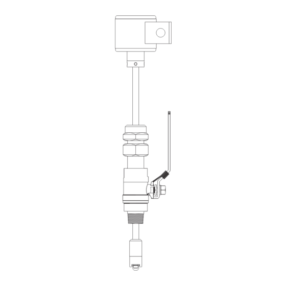
- Page 10 10. Slide the cover down the stem until it stops. Attach the sensor to the valve by inserting the impeller end of the stem into the valve until the cover touches the top of the valve. The sensor tip and impeller will be in the section of the valve above the ball.
-
Page 11: Electrical Installation
Electrical Installation Access wiring terminals by removing side cover. A wiring diagram is on the side cover, under the gasket. Use care when replacing side cover to insure that the gasket is in place. DO NOT REMOVE CIRCULAR COVER from top of sensor. You may disturb seal and label alignment. A moisture absorbing silica pack has been placed inside the electronics housing during assembly. - Page 12 Bi-Directional Analog Output - Option “5” in the ordering matrix This option provides a programmable 4-20 mA signal proportional to flow rate and a contact closure to indicate the direction of flow. All programming is accomplished as previously mentioned. The user can program the unit for pipe size, flow scale and the direction of flow.
- Page 13 Programming Programming the Series SDI is accomplished by installing the Data Industrial programming software on a computer and entering data on templates of the Windows based program. ® 1. Load the interface software into the computer. 2. Connect the computer to the SDI with the Data Industrial A-301 communications cable to the socket labeled “D.I.C Comm Port”, taking care to properly align the tab on the plug and socket to maintain polarity.
- Page 14 6. Program using diagram below as a reference. Single Direction Analog Output Models Step #1 Select rate units from the pull down Step #2 values. Select total units from the pull down values. Step #3 Select the pipe size from the pull See Note #1 down menu, if the pipe size is not present then custom must be...
- Page 15 Single Direction Scaled Pulse Output Models Step #1 Select rate units from the pull down Step #2 values. Select total units from the pull down values. Step #3 Select the pipe size from the pull See Note #1. down menu, if the pipe size is not present then select custom or check Step #4 for an updated pipe.dat table on the...
- Page 16 Bi-Directional Analog Output Models Step #1 Select rate units from the pull down Step #2 values. Select total units from the pull down values.. Step #3 Select the pipe size from the pull See Note #1. down menu, if the pipe size is not present then select custom or check Step #4 for an updated pipe.dat table on the...
- Page 17 Bi-Directional Scaled Pulse Output Models Step #1 Select rate units from the pull down Step #2 values. Select total units from the pull down values. Step #3 Select the pipe size from the pull See Note #1. down menu, if the pipe size is not present then select custom or check Step #4 for an updated pipe.dat table on the...
- Page 18 Battery Powered SDI Programming Programming the Series SDI is accomplished by installing the Data Industrial programming software on a computer and entering data on templates of the Windows based program. ® 1. Load the interface software into the computer. 2. Connect the PC to the SDI with the Data Industrial A-303 communications cable. Plug in the the RJ11 plug on the A-303 cable to the RJ11 socket on Battry Powered SDI.
- Page 19 5. Program parameters using diagram below as a reference. Step #1 Enter in a “K” number Step #4 found in Table B. Select the desired flow rate and total units. Step #2 Enter in a “offset” number found in Table B. Step #5 Step #3 Select the desired...
- Page 20 Table A Customer Reference Number Pipe Pipe Schedules SDR21 Size O.D. 40s/Std (200) Wall .109 .109 .145 .145 .200 1 1/2 1.900 Insertion Depth Customer Ref # 1 9/16 1 9/16 1 9/16 1 9/16 1 9/16 Wall .109 .109 .154 .154 .218...
- Page 21 Table A (cont.) Customer Reference Number Pipe Pipe Schedules Size O.D. 40s/Std .375 Wall .250 .218 .594 1.031 Insertion Depth 2.93 2.94 2.82 2.69 20.000 2.89 Customer Ref # 4 1/16 4 1/32 4 9/32 4 19/32 4 1/8 Wall .250 .375 1.125...
- Page 22 Table A (cont.) Customer Reference Number Ductile Iron Because of the variety of iron pipe classes, sizes, and wall thicknesses, consult factory for customer reference number. Pipe O.D. & Schedule, or pipe O.D. & I.D., or pipe O.D. & wall thickness is required. PVC AWWA C900 Size O.D.
- Page 23 Table B k & Offset Pipe Pipe Schedules SDR21 Size O.D. 40s/Std (200) 0.297315 0.297315 0.244927 1 1/2 1.900 Offset 0.859353 0.859353 0.859353 0.801632 0.801632 0.498124 0.498124 2.375 Offset 1.813024 1.813024 1.523850 1.523850 0.801632 0.801632 0.699870 0.699870 0.654225 2 1/2 2.875 Offset 1.813024...
- Page 24 Table B (cont.) Copper Tube Type Size O.D. 0.277993 1 1/2 1.625 Offset 0.063685 0.509285 2.125 Offset -0.043054 0.784450 2 1/2 2.625 Offset -0.126200 1.177171 3.125 Offset 0.198965 1.750507 4.125 Offset 4.142096 3.587835 5.125 Offset 0.198965 5.041780 4.298570 6.125 Offset 0.198965 3.295640 Ductile Iron...
-
Page 25: Specifications
- 150°F (65°C) Programming: Operating Temperature: LCD: - all programmable models utilize Data Industrial A-301 - 150°F (65°C) connector cable and SDI Series software Maximum Pressure Rating: Display: (optional) - 1000 psi @ 100°F - 8 character, 3/8” LCD 900 psi @ 200°F - STN (Super twisted Nematic) display 750 psi @ 300°F... - Page 26 (This page intentionally left blank.) 26 26...
- Page 27 (This page intentionally left blank.)
- Page 28 Due to continuous research, product improvements and enhancements, Badger Meter reserves the right to change product or system specifications without notice, except to the extent an outstanding contractual obligation exists. BadgerMeter, Inc. Copyright © Badger Meter, Inc. 2009. All rights reserved.
Need help?
Do you have a question about the SDI Series and is the answer not in the manual?
Questions and answers