
Related Manuals for Gas Clip Technologies Multi Gas Clip Simple Plus


Summary of Contents for Gas Clip Technologies Multi Gas Clip Simple Plus
- Page 1 Multi Gas Clip Simple Plus User’s Manual UM MGC-S-PLUS v1.00a Portable gas detectors you can count on 1 of 18...
-
Page 2: Table Of Contents
Multi Gas Clip Simple Plus User’s Manual CONTENTS Warning Statements/Avertisseement . . . . . . . . . . . . . . . . . . . . . . . . . . . . . . . . . . . . . . . . . . . . . . . . . . . 1 READ FIRST BEFORE OPERATION . -
Page 3: Warning Statements/Avertisseement
Ne remplacez pas les composants car cela pourrait interférer avec la sécurité intrinsèque de l’appareil . DO NOT substitute any other battery type than specified and supplied by Gas Clip Technologies . Only use Gas Clip Technologies parts in the detector . Non-approved parts will void the warranty and are considered unsafe . -
Page 4: Detector Components
Alligator Clip with Safety Ring Certification Label Model and Serial Label Included in the box: Multi Gas Clip Simple Plus Detector, MGC-S Calibration Cap, Multi Gas Clip Simple Plus Quick Start Guide & Calibration Certificate . UM MGC-S-PLUS v1.00a Portable gas detectors you can count on... -
Page 5: Display Components
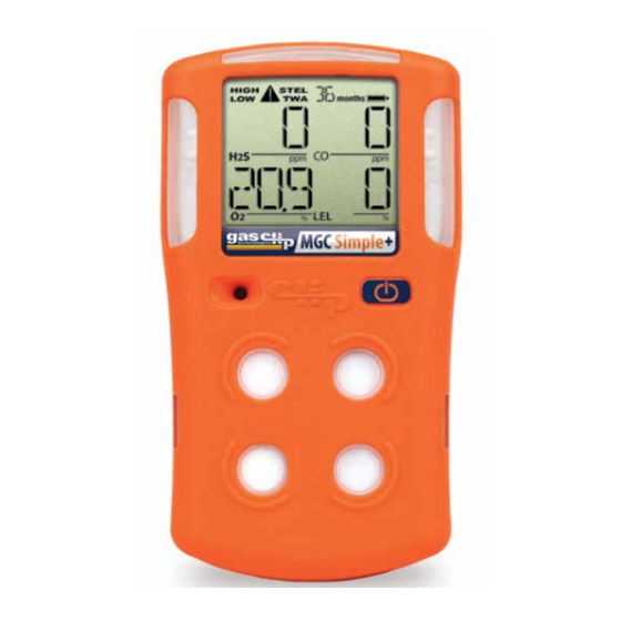
Multi Gas Clip Simple Plus User’s Manual DISPLAY COMPONENTS Display Layout Item Description Alarm Condition Life Remaining Calibration/Test Mode Battery Indicator Gas Readings Gas Identifiers Display Details When a detected gas has a Gas Reading (5) at or above its alarm thresholds, the Gas Identifier (6) for that particular gas will flash and a warning symbol will appear at the top of the display along with the associated Alarm Condition (1). -
Page 6: Basic Operation
Multi Gas Clip Simple Plus User’s Manual BASIC OPERATION Button Usage The following operations are driven by the Power/Menu Button located on the front of the detector: • Turning on the detector • Menu navigation • Main Menu • Status Menu •... -
Page 7: Alarms
Multi Gas Clip Simple Plus User’s Manual ALARMS Alarm Behavior The following table describes the detector’s behavior under various alarm conditions: Alarm Condition Audible Alarm Vibration Alarm Visual Alarm slow beep slow vibration slow LED flash High fast beep fast vibration... -
Page 8: Detector Menus
Multi Gas Clip Simple Plus User’s Manual DETECTOR MENUS Main Menu Once activated, the Main Menu is accessed by pressing the Power/Menu Button two separate times in quick succession (double- tap). The detector will display in the following order: 1. Life Remaining – Number of months and days left before the 36 month life of the detector expires. Months remaining will display until there are less than 30 days remaining. -
Page 9: Option Menu
The User ID/Message will be displayed right after the date and time each time the Main Menu is accessed. Default User ID/Message is "GAS CLIP TECHNOLOGIES". Alarm Limits - This option allows you to set sensor low and high alarm limits. Each sensor contains separate alarm threshold values that tell the detector when to go into alarm. - Page 10 Multi Gas Clip Simple Plus User’s Manual ADJUSTABLE OPTIONS continued TWA Method - The algorithm used to calculate the TWA (Time Weighted Average) can be set to either an average over a moving window (OSHA) or as a cumulative average (ACGIH).
-
Page 11: Detector Maintenance
Multi Gas Clip Simple Plus User’s Manual DETECTOR MAINTENANCE Battery This detector is designed so that the battery will not need to be charged during the life of the detector. If the battery is too low, the detector will display "LOW BAT". If this occurs prior to detector's end of life, contact GCT for technical support . - Page 12 Multi Gas Clip Simple Plus User’s Manual • When a bump interval has been programmed into the detector, but a bump test is not yet due, the current bump test status will show: “L. BUMP___” (the date of the last bump test) followed by “BUMP XXXd. ” (the number of days until the next scheduled bump test is due).
- Page 13 Multi Gas Clip Simple Plus User’s Manual • When a bump test has failed, the current bump test status will show: “L. BUMP FAILED” (indicating that the last bump test had failed). Audible, visual & vibrating prompting to apply gas will automatically start. The display will alternate between “BUMP DUE”...
-
Page 14: Calibration
Multi Gas Clip Simple Plus User’s Manual Calibration The detector can be configured to keep track of regular calibration intervals in a Calibration Log. The interval can be set using the GCT IR-Link software. When a calibration comes due, or if the last calibration has failed, then the detector’s display will continually flash “CAL DUE”... -
Page 15: Detector Records (Logs)
Multi Gas Clip Simple Plus User’s Manual DETECTOR RECORDS (LOGS) During operation, the detector automatically records all usage activity. These records can be downloaded from the detector using the or MGC Simple Clip Dock. The Event, Bump and Calibration Logs are always downloaded. Partial data logs may be downloaded in order to reduce the transfer time. -
Page 16: How To Retrieve Data Logs
Multi Gas Clip Simple Plus User’s Manual How to retrieve data logs using GCT IR Link *You must have Microsoft Excel to open Data and/or Event Logs *Computer System Requirements: Available for Windows© based PCs (Vista, 7, 8.x, 10) *Browser requirements: Google Chrome, Firefox, Opera or Edge Set detector in front of GCT IR Link with GCT IR Link Communication Window and MGC Simple Plus IR Communication Window lined up approximately 2-3 inches apart. -
Page 17: Accessories And Replacement Parts
Multi Gas Clip Simple Plus User’s Manual ACCESSORIES AND REPLACEMENT PARTS MGC-S Dock (P/N: MGC-S-DOCK) - Portable, chargeable all-in-one docking station in durable carry case for automated 4-detector simultaneous bump testing, calibrating, record keeping and programming - Also available in Hi-Pressure version... - Page 18 Filter - Pack of 10 (P/N: MGC-S-FILTER-10) Filter - Pack of 2 (P/N: MGC-S-FILTER-2) Various authorized replacement/spare parts for Multi Gas Clip Simple Plus detectors are available See the GCT website, www.gascliptech.com, for further details or contact GCT for pricing and availability.
-
Page 19: Detector Specifications
Multi Gas Clip Simple Plus User’s Manual DETECTOR SPECIFICATIONS Size 4.75 H x 2.75 W x 1.25 D in. (120.65 x 69.85 x 31.75 mm.) Weight 7.675 oz. (220.2 g) Temperature -4˚F to +122˚F (-20˚C to +50˚C) Humidity 5% to 95% RH (non-condensing) -
Page 20: Limited Warranty
LIMITED WARRANTY Gas Clip Technologies (“GCT”) warrants this product to be free from defects in material and workmanship under normal use and service for a period of two years beginning upon the date of activation for all Multi Gas Clip products. Date of activation allowance is limited to the “Activate before…” date provided on the shipment box label. This warranty extends only to the sale of new and unused products to the original buyer.
Need help?
Do you have a question about the Multi Gas Clip Simple Plus and is the answer not in the manual?
Questions and answers