Table of Contents
Advertisement
Advertisement
Table of Contents
Troubleshooting

Subscribe to Our Youtube Channel
Related Manuals for STIEBEL ELTRON WPL 15 IKS-2


Summary of Contents for STIEBEL ELTRON WPL 15 IKS-2
- Page 1 OPERATION AND INSTALLATION Air | water heat pump » WPL 15 IKS-2 » WPL 25 IK-2...
-
Page 2: Table Of Contents
Appliance description ������������������������������������� 20 17.1 Dimensions and connections ��������������������������������� 62 Mode of operation ���������������������������������������������� 20 17.2 Internal unit wiring diagram WPL 15 IKS-2 ���������������� 66 Standard delivery ���������������������������������������������� 20 17.3 Internal unit wiring diagram WPL 25 IK-2������������������ 68 Preparations ������������������������������������������������ 20 17.4... -
Page 3: Special Information
SPECIaL INfOrmaTION SPECIaL INfOrmaTION - Ensure that the refrigerant circuit is tested once a year for leaks, in accordance with EC DIRECTIVE 517/2014. The tightness test must be documented in the log. - The appliance may be used by children aged 8 and up and persons with reduced physical, sen- DHW cylinders sory or mental capabilities or a lack of experience... -
Page 4: Operation
OPEraTION General information OPEraTION Other symbols in this documentation Note Notes are bordered by horizontal lines above and below the text. General information is identified by the symbol General information shown on the left. f Read these texts carefully. The chapters „Special information“ and „Operation“ are intended for both users and qualified contractors. -
Page 5: Safety
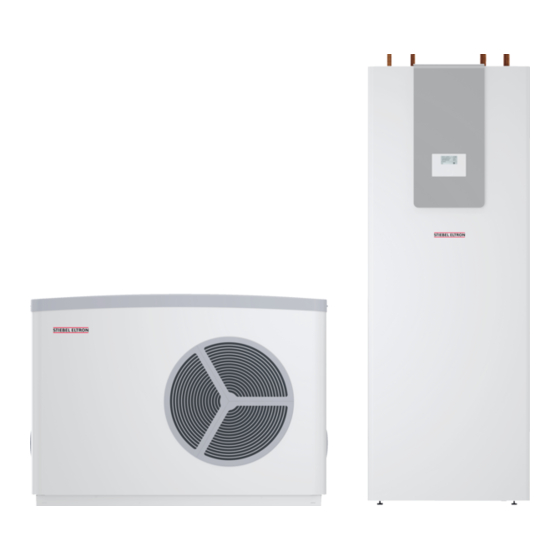
OPEraTION Safety Safety Appliance description The appliance comprises an internal unit (heat pump module) and Intended use an external unit (evaporator module). The appliance is used for heating rooms and domestic hot water. These two units are connected by refrigerant lines. Observe the application limits listed in the chapter „Specification / The external unit is designed for external installation and extracts Data table“. -
Page 6: Energy Saving Tip ������������������������������������������������ 6 12.6 Heat Pump Manager Commissioning Summary
OPEraTION Settings Settings Appliance functions - Fully automatic heating of heating water. Operation is divided into three control levels. Control levels 1 and - Suitable for underfloor heating and radiator heating systems; 2 are accessible to users and contractors alike. Control level 3 is preferentially for low temperature heating systems, as these reserved for contractors: achieve higher performance factors. -
Page 7: Essential Facts In Brief ������������������������������������������ 7 13.1 Standard Settings
OPEraTION Settings 4.1.2 System status display Note During commissioning, a system check will be imple- ROOM T HC1 mented, e.g. all sensors that are currently connected are displayed upon request. Sensors not connected before the system went 'live' are not registered by the heat pump manager and are therefore not displayed. -
Page 8: Adjustments At Control Level 1
OPEraTION Settings Adjustments at control level 1 Silent mode f Keeping the control flap closed, turn the rotary selector to Reduced noise mode the operating mode you wish to adjust. Silent mode is enabled. The associated time programs determine activation of the fan or compressor throttle. Standby mode Note Frost protection is activated for heating and DHW mode. -
Page 9: Adjustments At Control Level 2
OPEraTION Settings Under the PARTY menu item, you can extend the day mode by a 4.5.1 Room temperature, heating circuit 1 few hours. With menu item ROOM T HC1, you can select the set room tempe- rature for day and setback mode for heating circuit 1. Changing TEMPERATURES these parameters results in a parallel shift of the heating curve. - Page 10 OPEraTION Settings 4.5.2 Room temperature, heating circuit 2 4.5.3 DHW temperature With menu item ROOM T HC2, you can select the set room tem- Under menu item DHW TEMP, you can assign a set day and night perature for day and setback mode for heating circuit 2. ROOM T value for the temperature in the DHW cylinder.
- Page 11 OPEraTION Settings 4.5.4 Time and date 4.5.5 Holiday and party program You can adjust the time and summer time with the TIME/DATE In holiday mode, the heat pump system runs in setback mode menu item. and frost protection for DHW heating is enabled. HOLIDAY MODE is displayed when the flap is closed.
- Page 12 OPEraTION Settings 4.5.6 Temperatures MONTH END Under menu item TEMPERATURES, you can read off values of the heat pump and heat pump system. TEMPERATURES OUTSIDE HOLIDAY BACK BACK HOL PARTY TEMPERATURES Note Please note that actual and set values can only be display- ed if the appropriate sensors are connected.
- Page 13 OPEraTION Settings TEmPEraTUrES meaning OUTSIDE Outside temperature ACT ROOM T FE7 Actual room temperature for heating circuit 1 (HC1) or heating circuit 2 (HC2) (will only be displayed if the FE 7 remote control is connected) SET ROOM T FE7 Set room temperature for heating circuit 1 or heating circuit 2 (will only be displayed if the FE 7 remote control is connected) REL HUMIDITY Relative humidity (will only be displayed if the FEK remote control is connected)
- Page 14 OPEraTION Settings HEATING CURVES HTG CURVE Under HEATING CURVES, you can adjust the respective heating curves for heating circuits 1 and 2. It is very important that the correct heating curve is selected to ensure a constant room tem- perature. Note Your contractor will have set up a building and sys- tem-specific optimum heating curve for every heating circuit.
- Page 15 OPEraTION Settings Heating curve diagram Adapting a heating curve One heating curve each can be adjusted for heating circuit 1 and Example: heating circuit 2. During spring and autumn, it can occur that the temperature in a At the factory, heating curve 0.6 is set for heating circuit 1 and building is too low at an outside temperature between 5 °C and heating curve 0.2 for heating circuit 2.
- Page 16 OPEraTION Settings 4.5.7 HEATING PROG HEATING START The HEATING PROG menu item enables you to determine when and how often the appliance heats to the set day values for heating circuit 1 and heating circuit 2. At all other times, the appliance heats in setback mode.
- Page 17 OPEraTION Settings DHW START BACK HTG PROG DHW STOP 4.5.8 DHW programs DHW START The DHW PROGRAM menu item enables you to adjust the times for the day and night temperatures for DHW heating. You can adjust your DHW heating as follows: - For each individual day of the week (Monday –...
-
Page 18: Remote Control Fe 7
OPEraTION Settings Remote control FE 7 Note The heating curve, room temperature and heating pro- gram parameters are not shown at the WPMme heat pump manager if the FEK is pre-selected for a specific heating circuit. Internet Service Gateway (ISG) With the FE 7 remote control, the following options are available: - Changing the set room temperature for heating, for heating circuit 1 or 2, by ± 5 °C. -
Page 19: Maintenance And Care
OPEraTION maintenance and care Maintenance and care Troubleshooting fault Cause remedy Material damage There is no hot There is no voltage at Check the fuses/MCBs in your water or the hea- the appliance. fuse box. Replace the fuses/reset Maintenance work, such as checking the electrical safety, ting system stays the MCBs if required. -
Page 20: Safety
INSTaLLaTION Safety INSTaLLaTION Standard delivery 8.2.1 Standard delivery, internal unit Delivered with the appliance: Safety - 1 outside temperature sensor AFS 2 - 4 sliding blocks for the appliance feet Only a qualified contractor should carry out installation, commis- - 4 appliance feet sioning, maintenance and repair of the appliance. - Page 21 INSTaLLaTION Preparations Sound attenuation 45 dB(A) Sound attenuation of 45 dB(A) is achieved through a light- weight wall of a timber frame construction with full insulation. The cross-section of the timber supports should be 60 x 60 mm. The wall must have plasterboard panelling on both sides, with 12.5 mm on one side and 10 mm on the opposite side.
-
Page 22: External Unit
INSTaLLaTION Preparations 9.1.2 Minimum clearances 9.2.1 Sound emissions The appliance is louder on the air intake and air discharge sides than on the two enclosed sides. Observe the following information when selecting the installation location. Note For details regarding the sound power level, see chapter "Specification / Data table". -
Page 23: Refrigerant Lines
INSTaLLaTION Preparations f Therefore avoid routing refrigerant lines through living areas Material damage and bedrooms. Please note that the outdoor air must be able to flow f As much as possible, route refrigerant lines outside the buil- unimpeded into the appliance, and the exhaust air must ding wall. -
Page 24: Electrical Installation
INSTaLLaTION Preparations Electrical installation DANGER Electrocution Carry out all electrical connection and installation work in accordance with national and regional regulations. DANGER Electrocution Only use a permanent connection to the power supply. It must be possible to separate the appliance from the power supply by an isolator that disconnects all poles with at least 3 mm contact separation. -
Page 25: Appliance Installation
INSTaLLaTION appliance installation 10. Appliance installation 10.1 Internal unit 10.1.1 Transport WARNING Burns The appliance is filled with refrigerant. Escaping refri- gerant can cause burns. f Ensure that the appliance is not damaged. 1 Appliance foot Material damage 2 Sliding block The appliance is unsuitable for lifting by hoist. - Page 26 A condensate drain is fitted to the defrost pan at the factory, to enable the condensate to drain off. Example: Foundation slab WPL 15 IKS-2 1200 A Depth of frost line 1 Refrigerant suction gas line 2 Refrigerant, liquid line...
-
Page 27: Condensate Drain
INSTaLLaTION appliance installation Example: Strip foundation Example: T-support A Depth of frost line 1 Refrigerant suction gas line 2 Refrigerant, liquid line 3 Condensate drain A Depth of frost line 4 Foundation 1 Refrigerant suction gas line 5 Gravel bed 2 Refrigerant liquid line 6 Drainage pipe 3 Condensate drain... -
Page 28: Installing Supply Lines And Supply Cables
INSTaLLaTION appliance installation 10.5 Installing refrigerant lines f After routing the condensate hose, check that the condensate can drain correctly. Material damage If required, you can mount a ribbon heater on the condensate pan Prevent dirt and moisture from penetrating the refrige- and the condensate hose on site. - Page 29 INSTaLLaTION appliance installation 10.5.3 Connecting refrigerant lines Material damage Commissioning below+5 °C is only permissible if the pre-installed refrigerant lines are perfectly sealed and their ends point downwards, thereby preventing the in- gress of dirt and water. Purge the refrigerant lines tho- roughly with nitrogen.
- Page 30 INSTaLLaTION appliance installation 10.5.4 Tightness test Note After installation has been completed you are required to perform a tightness test in accordance with the applicable regulations. Never use any gas other than nitrogen to perform the tightness test on the pipes. f Evacuate the refrigerant lines and the pipework of the exter- nal unit.
-
Page 31: Heating Water Connection
INSTaLLaTION appliance installation f Size the discharge outlet so that water can drain off unimpe- ded when the safety valve is fully opened. f Ensure that the safety valve drain is open to the outside. f Install the safety valve drain with a constant fall to the discharge outlet. - Page 32 INSTaLLaTION appliance installation Filling the heating system Material damage The air vent in the knurled cap of the quick-action air vent Material damage valve must not point towards the MFG PCB. Never switch on the power before filling the system. f Turn the air outlet in the direction shown in the fol- lowing diagram.
-
Page 33: Dhw Connection
INSTaLLaTION appliance installation 10.7 DHW connection 10.9 Fitting the push-fit connectors Material damage Note Carry out all water connection and installation work in Never install the push-fit connectors in the DHW line. accordance with regulations. Only install the push-fit connectors in the heating circuit and the solar circuit. -
Page 34: Power Supply
INSTaLLaTION Power supply f Tighten the screw cap by hand against main body as far as it will go. This locks the push-fit connection. Undoing the push-fit connection If the push-fit connectors later need to be undone, proceed as follows: f Turn the screw cap anti-clockwise until there is a narrow gap of approx. - Page 35 Connect cables according to the following diagram. 11.2.2 Electric emergency/booster heater, compressor and fan WPL 15 IKS-2 X3 Electric emergency/booster heater (DHC) L1, L2, L3, N, PE Connected load Terminal allocation 2.9 kW...
- Page 36 INSTaLLaTION Power supply 11.2.4 Control voltage 11.2.5 Low voltage, BUS cable and service Control voltage (control outputs) Heating circuit pump and N (X25), PE Mixer closed Mixer open Enable signal Mixer circuit pump and N (X25), PE X30 Control voltage to external unit L, N, PE X2 Low voltage Material damage...
-
Page 37: Electrical Connection Of External Unit
INSTaLLaTION Power supply 11.3 Electrical connection of external unit f Connect cables according to the following diagram. Material damage The electrical cables for the control voltage and the power supply for the fan must be laid separately from each other. 11.3.1 Access to the connecting chamber mains (control voltage from internal unit) L, N, PE... -
Page 38: Connection Diagram Wpl 15 Iks-2
INSTaLLaTION Power supply 11.4 Connection diagram WPL 15 IKS-2 f Observe chapter “Electrical installation” when installing the electrical cables. 1 Control circuit 1/N/PE 230V 50Hz (domestic electricity meter) 2 Load circuit, heat pump 1/N/PE 230V 50Hz (heat pump electricity meter) -
Page 39: Connection Diagram Wpl 25 Ik-2
INSTaLLaTION Power supply 11.5 Connection diagram WPL 25 IK-2 f Observe chapter “Electrical installation” when installing the electrical cables. 1 Control circuit 1/N/PE 230V 50Hz (domestic electricity meter) 2 Load circuit, heat pump 3/N/PE 400V 50Hz (heat pump electricity meter) 3 Load circuit, booster heater 3/N/PE 400V 50Hz (heat pump electricity meter) 4 Power-OFF control (control phase L w/o blocking time;... -
Page 40: Remote Control Fek
INSTaLLaTION Power supply 11.6 Sensor installation Sensor resistance values Outside temperature sensor AFS 2 (included in the pack sup- Temperature in °C PT 1000-sensor PTC-sensor resistance in Ω resistance in Ω plied) - 30 1250 The temperature sensors have a significant influence on the func- - 20 1367 tion of your heating system. -
Page 41: Internet Service Gateway Isg
INSTaLLaTION Commissioning 11.9 Internet Service Gateway ISG 12.1 Checks before commissioning The Internet Service Gateway ISG enables you to operate the heat 12.1.1 Heating system pump in your local home network and via the internet when on - Have you set the flow rate on the heating side correctly? the go. -
Page 42: Minimum Flow Rate
INSTaLLaTION Commissioning 12.2 Minimum flow rate For heating operation without a buffer cylinder, always ensure the minimum flow rate and the availability of energy for defrosting. 12.3 Setting the flow rate on the heating side Material losses For operation without a buffer cylinder, it is essential that the electric emergency/booster heater (DHC) is connec- ted. -
Page 43: Operation And Control
INSTaLLaTION Commissioning f Fully open the heating circuit(s) in the lead room. f Close all other heating circuits. f If an overflow valve has been installed in the heating system, fully close this overflow valve in order to determine the mini- mum flow rate. - Page 44 INSTaLLaTION Commissioning 12.6 Heat pump manager commissioning summary Control level 3 Parameter (shown in the display) START UP CODE ENTRY LANGUAGE GERMAN BACK CONTRAST DISPLAY RETURN TEMP OUTSIDE TEMP DHW TEMP MIXER TEMP BACK ACTUAL FLOW T EMERG OPERTN ON / OFF HEAT-UP PROG ON / OFF LOW END TEMP...
- Page 45 INSTaLLaTION Commissioning DHW OUTP SUM DHW OUTP WINT DUAL-MODE DHW °C DELAY DHC DHW MAX DHC DHW °C SET DHW P RATE DHW ECO ON / OFF BACK DHW HYSTERESIS °C DHW CORRECTION °C DHW HC PUMP ON / OFF PASTEURISATION ON / OFF FLOW PROP HC1...
- Page 46 INSTaLLaTION Commissioning CODE ENTRY Where return temperatures are < 25 °C, the heat-up program / screed drying must be carried out via the emergency/booster he- Enter the correct four-digit code to change parameters at control ater. The process must not be carried out via the heat pump – such level 3.
- Page 47 INSTaLLaTION Commissioning After the heat-up process all modified parameters must be reset Now the start-up duration is brought to bear, e.g. at an outside to their standard values or system values. temperature of 5 °C, the pump starts 3 times per hour for 5 mi- nutes respectively.
- Page 48 INSTaLLaTION Commissioning Summer logic remains disabled with fixed temperature control. mixer circuit data, the maximum set mixer flow temperature will This means that the heating circuit pump is not switched off for be used to control and regulate to this value. the direct heating circuit.
- Page 49 INSTaLLaTION Commissioning FROST PROTECT Incorrectly set heating curves are corrected by the room sensor in- fluence K; whilst the smaller factor K provides more stable control. To protect the heating system from frost, the heating circuit pumps However, observe the following for all control units with room are started at the selected frost protection temperature;...
- Page 50 INSTaLLaTION Commissioning SET HTG P RATE When heating DHW, the system automatically adjusts itself to the required DHW temperature (self-learning function). Circulation pump output during heating operation in %. As soon as the heat pump is shut down in DHW mode via a fault DHW OUTP SUM or via the maximum DHW flow temperature, the electric emer- gency/booster heater will be switched on as a booster stage.
- Page 51 “–20 °C”. to 10 minutes after completing the necessary work. The required output diagrams can be found in chapter “Specifi- cation / Output diagram WPL 15 IKS-2” and chapter “Specification COMP DLAY CNTR / Output diagram WPL 25 IK-2”. Pressing PRG enables you to call up the compressor idle time.
- Page 52 INSTaLLaTION Commissioning After that, the heat pump and the associated buffer primary pump WPMME SOFTWARE are switched on. Display of the current software issue. f Press the programming key again or close the control flap to exit the parameter. MFG SOFTWARE OFF is displayed.
-
Page 53: Wpmme Commissioning Report
INSTaLLaTION Commissioning 12.7 WPMme commissioning report Parameter Setting range Standard System value Enter code 0000 to 9999 1000 Language English Contrast -10 to +10 Display Actual return Emergency mode ON / OFF Heat up programme ON / OFF Low end temperature (AHP) 20...40 °C, incr 0.5 K 25.0 °C Low end temperature duration (AHP) -
Page 54: Settings
INSTaLLaTION Settings Analysis Diagnosis Manual defrost ON / OFF Heat pump reset ON / OFF Runtimes 13. Settings 13.2.2 Heating program, heating circuit 2 Switching time Switching time Switching time 13.1 Standard settings pair I pair II pair III At the factory, the heat pump manager is programmed with the following standard settings: Switching times for heating circuit 1 and 2 (day mode);... -
Page 55: Appliance Handover
INSTaLLaTION Shutting down 14. Shutting down 13.2.4 Silent mode 2 Switching time Switching time Switching time Material damage pair I pair II pair III Never interrupt the power supply, even outside the he- ating period. The system's active frost protection is not guaranteed if the power supply is interrupted. - Page 56 INSTaLLaTION Troubleshooting 15.1.1 Heat pump-specific or hardware faults 15.1.3 The heat pump does not run All faults are displayed. The heat pump is in standby mode [ ]. f Change the system over to automatic mode. Example: Heat pump fault Power supply blocked;...
-
Page 57: Resetting The High Limit Safety Cut-Out
INSTaLLaTION Troubleshooting 15.2 Resetting the high limit safety cut-out If the heating water temperature exceeds 85 °C, the electric emer- gency/booster heater shuts down. 1 High limit safety cut-out reset button Electric emergency/booster heater f Remove the cause of the fault. f Reset the high limit safety cut-out by pressing the reset but- ton. - Page 58 INSTaLLaTION Troubleshooting 15.4 Fault tables Fault list for hydraulic sensors fault display Cause remedy ERR T FRO MFG The condenser sensor is faulty. Check the sensor terminal on the MFG or replace sensor. ERR T RTRN MFG The return sensor is faulty. Check the sensor terminal on the MFG or replace sensor.
- Page 59 INSTaLLaTION Troubleshooting Fault list for refrigerant circuit faults fault display Cause remedy ERR DEFROST Defrosting has been terminated. Check flow rate and temperatures during defrosting. ERR LP Low pressure too low (< 0.1 MPa for 10 s) The system is locked. A heat pump reset is required. ERR MIN SUPHT Superheating upstream of compressor too low (< 3 K for 60 s) The system is locked.
-
Page 60: Maintenance
INSTaLLaTION maintenance 16. Maintenance WARNING Electrocution f Before working on the appliance, isolate it from the power supply at the control panel. Following isolation from the mains supply, parts of the appliance may remain live for up to 2 minutes since the capacitors still have to discharge into the inverter. -
Page 61: Replacing The Signal Anodes
INSTaLLaTION maintenance 16.2 Replacing the signal anodes 16.4 Maintenance work on the external unit Material damage On the external unit, keep the air discharge and intake apertures free from snow and ice. 1 Signal indicator red f Replace the signal anodes if the red signal indicator on the user interface illuminates. -
Page 62: Dimensions And Connections
INSTaLLaTION Specification 17. Specification 17.1 Dimensions and connections 17.1.1 WPL 15 IKS-2 internal unit and WPL 25 IK-2 internal unit WPL 15 IKS-2 WPL 25 IK-2 Entry electrical cables Cold water Inlet Diameter DHW outlet Diameter Safety valve drain Heating flow Diameter Heating return Diameter... - Page 63 INSTaLLaTION Specification 17.1.2 WPL 15 IKS-2 external unit 1088 WPL 15 IKS-2 Entry electrical cables Condensate drain Air intake Air discharge Refrigerant suction gas line Diameter Refrigerant liquid line Diameter www.stiebel-eltron.com WPL 15 IKS | WPL 25 IK |...
- Page 64 INSTaLLaTION Specification 17.1.3 WPL 25 IK-2 external unit 1063 1108 1160 1270 WPL 25 IK-2 Entry electrical cables Condensate drain Air intake Air discharge Refrigerant suction gas line Diameter Refrigerant liquid line Diameter | WPL 15 IKS | WPL 25 IK www.stiebel-eltron.com...
- Page 65 INSTaLLaTION Specification www.stiebel-eltron.com WPL 15 IKS | WPL 25 IK |...
- Page 66 INSTaLLaTION Specification 17.2 Internal unit wiring diagram WPL 15 IKS-2 M _ _ M _ _ 1 2 3 > p 1 2 3 1 2 3 1 2 3 zu A7/PE Inverter BLK YEL an Sternpunkt Inverterrahmen von X23 von A5/X70 >...
- Page 67 INSTaLLaTION Specification 10 11 12 13 P3=2900W P2=2900W 1 2 3 P1=2900W PWM-Signal zu M2 X 10 X 11 X 12 X 13 X 14 X 15 X 20 X 21 X 22 www.stiebel-eltron.com WPL 15 IKS | WPL 25 IK |...
-
Page 68: Internal Unit Wiring Diagram Wpl 25 Ik-2
INSTaLLaTION Specification 17.3 Internal unit wiring diagram WPL 25 IK-2 M _ _ M _ _ 1 2 3 > p 1 2 3 1 2 3 1 2 3 zu A7/PE Inverter L1 L2 L3 GRD von X28/PE von X23 L1 L2 >... - Page 69 INSTaLLaTION Specification L1 L2 9 10 P3=2900W P2=2900W 1 2 3 P1=2900W PWM-Signal zu M2 X 10 X 11 X 12 X 13 X 14 X 15 X 20 X 21 X 22 www.stiebel-eltron.com WPL 15 IKS | WPL 25 IK |...
- Page 70 INSTaLLaTION Specification Key to internal unit wiring diagram Motor, diverter valve WPL 15 IKS-2 and WPL 25 IK-2 Stepper motor, injection valve Heat pump manager WPMme Stepper motor, expansion valve El. assy WPL 20/26 AZ/Hestia High pressure sensor A2/X1 6-pole plug, el. assy...
-
Page 71: External Unit Wiring Diagram Wpl 15 Iks-2 And Wpl 25 Ik-2
INSTaLLaTION Specification 17.4 External unit wiring diagram WPL 15 IKS-2 and WPL 25 IK-2 > T M _ _ Das Entstörglied Z12 umfasst die drei markierten Kabel RCC refrigerant circuit controller Mains terminal A1/X1 Power supply Mains terminal, fan A1/X2... -
Page 72: Performance Diagram Wpl 15 Iks-2
INSTaLLaTION Specification 17.5 Performance diagram WPL 15 IKS-2 Outside temperature [°C] Heating output [kW] max. W55 max. W45 max. W35 min. W55 min. W45 min. W35 | WPL 15 IKS | WPL 25 IK www.stiebel-eltron.com... -
Page 73: Performance Diagram Wpl 25 Ik-2
INSTaLLaTION Specification 17.6 Performance diagram WPL 25 IK-2 Outside temperature [°C] Heating output [kW] max. W55 max. W45 max. W35 min. W55 min. W45 min. W35 www.stiebel-eltron.com WPL 15 IKS | WPL 25 IK |... -
Page 74: Data Table
The power consumption figures for the integral auxiliary drives are maximum values and may vary subject to operating point. The power consumption of the integral auxiliary drives is included in the output details of the heat pump (to EN 14511). WPL 15 IKS-2 WPL 25 IK-2... - Page 75 INSTaLLaTION | GUaraNTEE | ENVIrONmENT aND rECYCLING Specification WPL 15 IKS-2 WPL 25 IK-2 Versions Compressor oil Emkarate RL 32 3MAF / MOBIL EAL Arctic Emkarate RL 32 3MAF / MOBIL EAL Arctic 22 CC 22 CC Condenser material 1.4401/Cu 1.4401/Cu...
- Page 76 Deutschland Verkauf Tel. 05531 702-110 | Fax 05531 702-95108 | info-center@stiebel-eltron.de STIEBEL ELTRON GmbH & Co. KG Kundendienst Tel. 05531 702-111 | Fax 05531 702-95890 | kundendienst@stiebel-eltron.de Dr.-Stiebel-Straße 33 | 37603 Holzminden Ersatzteilverkauf Tel. 05531 702-120 | Fax 05531 702-95335 | ersatzteile@stiebel-eltron.de Tel.
Need help?
Do you have a question about the WPL 15 IKS-2 and is the answer not in the manual?
Questions and answers