
Related Manuals for frako PQC


Summary of Contents for frako PQC
- Page 1 OPERATING MANUAL Power Quality Controller The controller that maximizes reliability and monitors power quality FRAKO Kondensatoren- und Anlagenbau www.frako.com...
-
Page 2: Table Of Contents
5.3.2 PQC initial start-up........ - Page 3 Decommissioning the PQC ........
-
Page 4: About This Manual
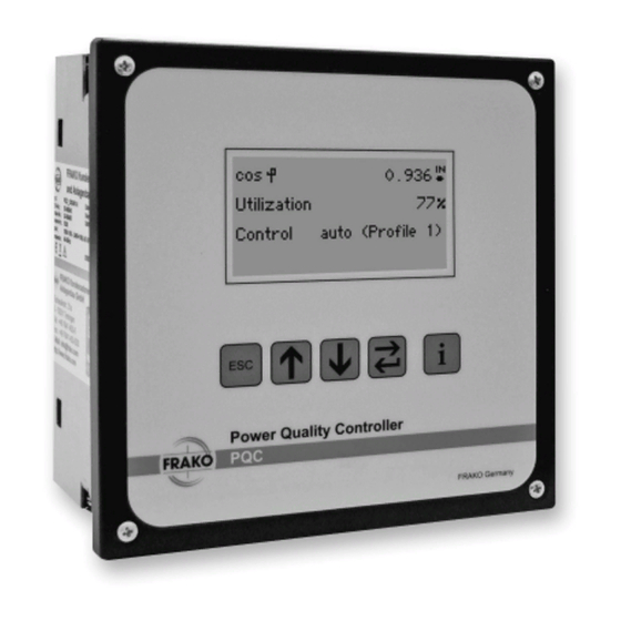
About this manual The PQC Power Quality Controller is an instrument for controlling the power factor and other power quality parameters. Throughout this manual, it will be referred to simply as the PQC. The current version of this manual can be accessed at our website: www.frako.com. -
Page 5: Reference Documents
Damage to property could occur if this sign is not heeded. Notes Notes supplement the general text with additional information on the correct func- tioning and fault-free operation of the PQC. They are marked with the white-on-blue symbol on the left-hand side, as shown below: Note... -
Page 6: Safety
– Current transformer circuits must be short-circuited before they are interrupted. – Only approved installation cables must be used. – The PQC must only be employed on duties up to the specified maximum power. Overloading the instrument can result in its destruction, create a fire hazard or cause an electrical accident. -
Page 7: Management Information
Social Accident Insurance Institution covering electrical installations. In other countries, the equivalent local regulations must be followed. The safety of the system in which the PQC is incorporated is the responsibility of the persons installing and operating the system. -
Page 8: Relevant Standards
Repair Should repair work be necessary, the customer or user must contact the manufacturer of the PQC: FRAKO Kondensatoren und Anlagenbau GmbH, Tscheulinstrasse 21A, D-79331 Teningen, Germany, www.frako.com. 8 | Safety Power Quality Controller – PQC | Operating Manual | FRAKO... -
Page 9: Technical Data
V transformer; measurement inputs In areas where UL / CSA standards apply (versions PQC xxx480x-xx): networks with nominal voltages 115–600 V AC; power failure detection after duration of a half-wave x/5 A AC or x/1 A AC (transformer secondary current ≥ 15 mA), electri-... - Page 10 Note: utilization category AC-14/DC-13 as per IEC 60947-5-1; for all PQC types in areas where UL / CSA standards apply: 3 A 250 V AC cos φ = 1 at 85 °C, 3 A 30 V DC L/R = 0 ms at 85 °C 10 | Technical data Power Quality Controller –...
- Page 11 250 V AC, 70 °C min. 500 V AC, 70 °C Conductor cross section max. 2.5 mm², min. 0.2 mm² Alarm contact Insulation rating: min. 250 V AC, 70 °C Technical data | 11 FRAKO | Operating Manual | Power Quality Controller – PQC...
- Page 12 (Article No. 20-50015) IP54; rear of instrument Ingress protection and terminals IP20; all as per EN 60529 Pollution degree 2 as per EN 61010-1:2011-07. 12 | Technical data Power Quality Controller – PQC | Operating Manual | FRAKO...
- Page 13 (20th harmonic of 50 Hz = 1 kHz). It is therefore to be expected that the measuring circuit clearly respond to the standard test. For this reason, the radio-frequency field test can only be carried out without amplitude modulation. Technical data | 13 FRAKO | Operating Manual | Power Quality Controller – PQC...
- Page 14 Voltage and current measurement ±1% at 50/60 Hz and 25 °C ambient Accuracy temperature Averaging function Over 1 second, updated every 100 ms Measured via Lx–N Harmonics All even and uneven harmonics up to the 19th 14 | Technical data Power Quality Controller – PQC | Operating Manual | FRAKO...
-
Page 15: Instrument Description
Regeneration The PQC has a four-quadrant control function. If active power is fed back into the sup- ply network, for example by combined heat and power systems, the PQC continues to correct for the reactive power drawn from the supply network. When this regeneration occurs, the active power P is displayed with a minus sign before it. -
Page 16: Instrument Versions
Instrument versions The PQC is available in various versions, identifiable by their type designation: – Type designation – Example – Measurement inputs: 1 = Temperature (I/O extension) Interface: 2 = Modbus RTU 3 = Ethernet 4 = FRAKO Starkstrombus (Frakobus) -
Page 17: Password Protection
Protected menu items: – Main menu > Parametrization Security level 1, Password: last four digits of the serial number (see label on PQC or Section 6.4 “About PQC”. – Main menu > Parametrization > Service > Reset switching cycles –... -
Page 18: Installation
(see also Section 2.1 “Intended use” and Section 3 “Technical data”): – Only install the PQC in areas where there is no danger of gas or dust explosions. – Do not expose the PQC to direct sunlight or high temperatures, and do not install the instrument near to devices that generate heat. -
Page 19: Mounting The Instrument
Mounting the instrument The PQC is designed for mounting in a 138 mm x 138 mm cutout to IEC 61554 in the front of a control cabinet. It is held in place by four retaining lugs in the corners of the instrument. -
Page 20: Electrical Installation
– All live components in the vicinity must be covered to prevent inadvertent contact. 1. Turn the four retaining screws at the front of the PQC anticlockwise so that the four retaining lugs in the corners of the instrument are swivelled to lie flat behind its front panel. -
Page 21: Completing The Electrical Installation
WARNING! Danger from electricity! If there is a fault in the wiring adjacent to the PQC, there is a danger that its four retaining screws could become live and therefore a safety haz- ard. Touching live components at the instrument terminals and connecting cables can cause serious injury or may even be life-threatening. -
Page 22: Specifications For The Electrical Connections
An external disconnecting device, such as an isolator or circuit breaker, must be fitted in the power supply line to the PQC. This must be located in the vicinity of the instrument and must be able to isolate all cables connected to the AUX terminals of the PQC. -
Page 23: Voltage Measurement
5.2.6 Voltage measurement Depending on the instrument type, the PQC can measure one, two or three AC volt- ages. The voltage measurement inputs are electrically interconnected via high resist- ances. See Section 3 “Technical data” for the measurement ranges. DC voltages cannot be measured. -
Page 24: Current Measurement
The PQC is designed for connection to x/1 A and x/5 A external current transform- ers electrically isolated from the power supply. Depending on the instrument type, the PQC can measure one, two or three AC currents. Attention must be paid to the allowable measurement range. See Section 3 “Technical data” for further information. -
Page 25: Output Relays (Control Outputs)
5.2.8 Output relays (control outputs) Depending on instrument type, the PQC is equipped with 6 or 12 output relays (con- trol outputs). Relays or contactors are usually connected to these to switch the capac- itor stages in and out. The output relays Q1–Q12 (Q1–Q6 in the case of PQC versions with 6 output relays) receive their control voltage from a common feed P. - Page 26 Messspannung Versorgungsspannung voltage measurement supply voltage 100V–690VAC~ VDE 100V-15% – 240V+10% AC~5VA Alarmrelais Ausgangsrelais alarm relays output relays φ φ 250VAC~ 3A cos 250VAC~ 3A cos Alarm 26 | Installation Power Quality Controller – PQC | Operating Manual | FRAKO...
- Page 27 100V–690VAC~ VDE 100 V-15% – 480 V+10% AC~5VA 100V–600VAC~ UL Alarmrelais Ausgangsrelais alarm relays output relays φ φ 250VAC~ 3 A cos 250VAC~ 3A cos Alarm Installation | 27 FRAKO | Operating Manual | Power Quality Controller – PQC...
- Page 28 Part of connection diagram for 400/415 V networks with no neutral conductor 2 A T 2A T Instrument type: PQC xxx480x-xx 400 V AC / 415 V AC – Networks with no neutral N 28 | Installation Power Quality Controller – PQC | Operating Manual | FRAKO...
-
Page 29: Commissioning (Initial Start-Up)
Touching live components at the instrument terminals and connecting cables can cause serious injury or may even be life-threatening. – It must be verified that the PQC is installed and connected in accordance with its intended use before power is switched on. -
Page 30: Pqc Initial Start-Up
When the power is switched on, the PQC Start screen is displayed, showing informa- tion about the installed firmware. The initial start-up dialogue then starts automatically, in which the essential parameters for operation can then be set and the start-up mode selected. -
Page 31: Automatic Connection And Stage Identification
PQC overview screen. If at this moment there is a concrete need for reactive power control, the PQC commences to switch stages in or out as necessary. If the PQC was not able to complete the connection and stage identification proce- dure successfully, or if the user presses the ESC key to cancel it, this is indicated by a message on the screen. -
Page 32: Manual Connection And Stage Identification
When all the necessary information has been entered, confirm this with Continue. The PQC then switches to operating mode and displays the PQC overview screen. If at this moment there is a concrete need for reactive power control, the PQC commences... - Page 33 V · k = response current in mA to be set = capacitive power of smallest stage in var (not the total capacitive power smallest stage of the system) Installation | 33 FRAKO | Operating Manual | Power Quality Controller – PQC...
- Page 34 100 120 140 190 240 290 480 1500/5 100 130 160 190 320 100 120 140 240 2000/5 2500/5 100 120 190 3000/5 100 160 4000/5 1000 5000/5 6000/5 1200 7000/5 1400 34 | Installation Power Quality Controller – PQC | Operating Manual | FRAKO...
-
Page 35: Description Of The Menu
System parameters PFC Equip. System & PQ parameter Control Service parameters Alarms & Alarms Sys time notific. Communica- tion (dyn.) Temp. I/O (dyn) Service Description of the menu | 35 FRAKO | Operating Manual | Power Quality Controller – PQC... -
Page 36: Display
Service Cap. stage Kvar Switching Temperatures I/O status Configuration status diagram diagram (dyn.) (dyn.) Alarms & notific. Alarms & Min/Max Alarm history notific. Data 36 | Description of the menu Power Quality Controller – PQC | Operating Manual | FRAKO... -
Page 37: Pqc Overview
6.2.1.2 Capacity utilization Main menu > Display > PQC overview > Cap. utilization Capacity utilization The ratio of the momentary switched-in capacitance to the total available capacitance, expressed as a percentage. - Page 38 This parameter is the 3-phase capacitor corrective power still available for switching in. 6.2.1.3 Control outputs Main menu > Display > PQC overview > Control outputs The overview display shows the momentary statuses of all the capacitor stages. Stages 1, 4, 5, 7, 10, 11: switched-out active stages...
-
Page 39: System & Pq
(if capacitive reactive power with a minus sign) Display of the momentary current Display of the momentary apparent power Sum of all the phases (L1 to L3); if a single-phase PQC, theoretical ∑ calculation of the sum assuming a balanced load 6.2.2.2 THD... - Page 40 Angle γ Angle between V (fundamental) and I in degrees Frequency Frequency Info status Select phase – Action +10 Hz –10 Hz 40 | Description of the menu Power Quality Controller – PQC | Operating Manual | FRAKO...
-
Page 41: Service
(discharge time) This is the stage corrective power in var (3-phase stage Q[var] corrective power). Number of stage switching cycles Switching cycles Description of the menu | 41 FRAKO | Operating Manual | Power Quality Controller – PQC... -
Page 42: Alarms & Notifications
I/O extension and indicates the status of each. 6.2.4 Alarms & notifications Main menu > Display > Alarms & notific. Status of the momentary alarms Display of Alarms and Min/Max histories. 42 | Description of the menu Power Quality Controller – PQC | Operating Manual | FRAKO... - Page 43 (sorted by time). Selecting one of the lines shown and pressing the key causes the alarm condition to be displayed in plain language. Description of the menu | 43 FRAKO | Operating Manual | Power Quality Controller – PQC...
- Page 44 • NTC1 • NTC2 Note Pressing the key shows the times elapsed since the minimum and max- imum values displayed on the screen occurred. 44 | Description of the menu Power Quality Controller – PQC | Operating Manual | FRAKO...
-
Page 45: Configuration
Communica- tion (dyn.) Alarms Relay settings Temp. I/O (dyn.) Service Factory Reset Reset alarm Manual Reset switch. Commissioning Service control settings count Min/Max history Description of the menu | 45 FRAKO | Operating Manual | Power Quality Controller – PQC... -
Page 46: System Parameters
If the system is not detuned, 0 % must be entered.) 6.3.3 Control parameters Main menu > Parametrization > Control parameters 46 | Description of the menu Power Quality Controller – PQC | Operating Manual | FRAKO... - Page 47 (profile switching)” 6.3.3.2 Settable control profiles Main menu > Parametrization > Control parameters > Control profiles > Profile Description of the menu | 47 FRAKO | Operating Manual | Power Quality Controller – PQC...
- Page 48 Further information is given in the “PQC Application Note“ Control profile parameters (Edit profile) Parameter Profile selection Select Select Action selection Back to – parameter parameter (Save Yes/No) parameter selection 48 | Description of the menu Power Quality Controller – PQC | Operating Manual | FRAKO...
- Page 49 Parallel shift = 0 Switch in Regeneration If the system operates within the Active power band range shown, no switching operations will be activated. Switch out Description of the menu | 49 FRAKO | Operating Manual | Power Quality Controller – PQC...
- Page 50 Active power Regeneration target upper limit of the control band. Switch out Overcompensation is avoided. One division = 0.65 × smallest cap. stage 50 | Description of the menu Power Quality Controller – PQC | Operating Manual | FRAKO...
- Page 51 One division = 0.65 × smallest cap. – Overcorrection (capacitive, stage usually disruptive) is avoided in the low load range. Description of the menu | 51 FRAKO | Operating Manual | Power Quality Controller – PQC...
- Page 52 5 and 500 seconds in 5-second incre- Switch out ments. When a stage is to be switched in or out, the PQC waits for this switching delay to elapse before switching takes place. If more stages are required, the switching time delay is shortened in accordance with the number of stages concerned (e.g.
- Page 53 Selecting the controlled phase The Control profiles menu also includes the Phase set- ting. This is used to select the phase used by the PQC for control purposes (can only be edited on 3-phase PQCs).
-
Page 54: Alarms
– Transmission via alarm relay If the alarm relay function is assigned to an alarm, the alarm relay incorporated in the PQC switches when the alarm occurs (connections: Alarm a, b) and remains in that state as long as the alarm is active. - Page 55 – Alarm signal via Temperature I/O output If the PQC has the Temperature I/O option, the alarms can also be connected to separate outputs. The assigned output remains switched on for the duration of the alarm concerned (NO mode only).
- Page 56 10 % of the set nominal network voltage. 6.3.4.5 Undercurrent Cannot be adjusted. Triggered when the measured secondary Alarm limit current drops below 10 mA. 56 | Description of the menu Power Quality Controller – PQC | Operating Manual | FRAKO...
- Page 57 Setting range: OFF to 95 % (OFF: In the power factor correction process, there is no monitoring of stage corrective power.) Note If the PQC is calibrated manually, this alarm is automatically deactivated and the alarm limit set at OFF. 6.3.4.8 THDi...
- Page 58 For this very important function to operate effectively, it is vitally important that the phase selected for the instrument power supply to the switching outputs is the same one selected for the voltage measurement. 58 | Description of the menu Power Quality Controller – PQC | Operating Manual | FRAKO...
-
Page 59: Communication (Optional)
6.3.4.13 Inputs I/O 1–I/O 5 (optional temperature I/O extension) An activated input of the temperature and I/O extension can allow the PQC to process logical signals. Example: Interruption of the control function when a logical 1 is received. The possi- bilities here are extremely diverse. - Page 60 Data bits 5 to 8 Stop bits 1 or 2 even, odd or none Parity Note Further details are described in the Modbus Specification. 60 | Description of the menu Power Quality Controller – PQC | Operating Manual | FRAKO...
- Page 61 When these settings have been made, the available services (Modbus TCP, web server) can be accessed in the network. The PQC is accessible via the Modbus TCP/IP protocol and port 502 at the set IP address. The data that can be retrieved are listed in the FRAKO Modbus Specification.
-
Page 62: Temperature I/O (Optional)
φ 250VAC~ 3A cos 250VAC~ 3 A cos Alarm Frakobus The PQC bus address can only be changed at the instru- ment itself. 6.3.6 Temperature I/O (optional) Typical circuits for the passive digital inputs and outputs, plus the temperature meas-... - Page 63 The terminals 1 to 5 can be configured for the particular application as inputs or out- puts in the PQC: Main menu > Parametrization > Temp. I/O (dyn.). If the configured inputs or outputs as used as alarms, the alarm routes can be set in the Alarms menu (see Section 6.3.4 “Alarms”).
-
Page 64: Service
One input can be used to switch between control profiles 1 and 2. This is configured in the PQC by navigating as follows: Main menu > Parametrization > Temp. I/O (dyn.). When this option is active, profile switching takes place exclusively via this... - Page 65 P and Q. 6.3.7.3 Factory default settings Main menu > Parametrization > Service > Factory settings Resets the PQC at its factory default settings (without affecting the switching cycle counter). 6.3.7.4 Clear switching cycles counters Main menu > Parametrization > Service > Clear switching cycles Reset switching cycle counters for all stages to zero (singly or individually, service password necessary);...
-
Page 66: About Pqc
System parameters (Section 6.3.2 “PFC Equip. parameter”) Choke factor System parameters Control parameters (Section 6.3.3 “Control parameters”) Cyclic switching Discharge time 60 s Control parameters Fixed stages 66 | Description of the menu Power Quality Controller – PQC | Operating Manual | FRAKO... - Page 67 45 s Phase Active Alarms (Section 6.3.4 “Alarms”) Alarms Relay function NO (normally open) Control band alarm Alarm relay cos φ alarm Display Emergency trip Description of the menu | 67 FRAKO | Operating Manual | Power Quality Controller – PQC...
- Page 68 Emergency trip Alarm limit 80 % Alarm relay Zero stage detection Display Emergency trip Alarm limit 50 % Alarm relay THDi Display Emergency trip 68 | Description of the menu Power Quality Controller – PQC | Operating Manual | FRAKO...
- Page 69 Communication (Section 6.3.5 “Communication (optional)”) Slave address Baud rate 19200 Modbus RTU Data bits Parity None Stop bits DHCP 0.0.0.0 Modbus TCP Subnet 0.0.0.0 Gateway 0.0.0.0 Description of the menu | 69 FRAKO | Operating Manual | Power Quality Controller – PQC...
-
Page 70: Service Interface
I/O 5 Input Service interface The PQC has a service interface in the form of a Micro USB port. This is used for servicing tasks such as firmware updates. Note Use of this interface is solely for the use of trained FRAKO Service per- sonnel. -
Page 71: General Operation
General operation The following points must be observed when the PQC is operated: – The instrument must always be operated in a closed control cabinet. – All voltages applied to the instrument must never exceed the limits specified in the technical data. -
Page 72: Cleaning And Maintenance
– All connections must be checked to verify that they are no longer live. – All live components in the immediate vicinity must be covered. Cleaning The PQC may only be cleaned with a dry cloth. Do not use aggressive or abrasive cleaning agents or solvents. Maintenance The PQC does not contain any components that need maintenance. -
Page 73: Troubleshooting
Troubleshooting If alarms occur during operation of the PQC, the following table provides assistance in identifying and remedying the faults. Alarm Fault Possible cause Remedial action message PQC not working; No power – or the wrong Check that the correct no display at front of voltage –... - Page 74 (voltage sag) not detected Stages not detected Triggered if a voltage sag causes the RMS voltage to fall below the set limit within the duration of a half-wave 74 | Troubleshooting Power Quality Controller – PQC | Operating Manual | FRAKO...
- Page 75 PQC according to the table. switched in and out was programmed. (hunting). Severe load fluctuations; Set higher delay time. the delay time was set too low. Troubleshooting | 75 FRAKO | Operating Manual | Power Quality Controller – PQC...
- Page 76 Neutral not connected to activated. contactors. Note Additional error messages are described in the “PQC Application Note”. 76 | Troubleshooting Power Quality Controller – PQC | Operating Manual | FRAKO...
-
Page 77: Decommissioning And Removal, Storage And Disposal
The instrument terminals can become hot during operation and could cause burns. – After the PQC has been operating, sufficient time must be allowed for the instrument and its terminals to cool down before work is carried out on the connections. -
Page 78: Pqc Removal
10.2 PQC removal The PQC is held in place against the rear of the cabinet front wall by four retaining lugs in the corners of the instrument. These can be released by undoing the retaining screws. 1. Turn all four screws anticlockwise with a screwdriver. This slackens the four retaining lugs and swivels them to lie flush behind the PQC front panel. - Page 79 Notes | 79 FRAKO | Operating Manual | Power Quality Controller – PQC...
- Page 80 Power capacitors Reactive power controllers Power factor correction systems Modules EMS components Measuring instruments and network analysers Power quality EMS ISO 50001 FRAKO Kondensatoren- und Anlagenbau GmbH Tscheulinstraße 21a D-79331 Teningen Phone: +49 7641 453-0 Fax: +49 7641 453-535 sales@frako.de www.frako.com...
Need help?
Do you have a question about the PQC and is the answer not in the manual?
Questions and answers