Table of Contents
Advertisement
Quick Links
- 1 Section 2: Installation Considerations
- 2 Section 3: Configuration Considerations
- 3 Section 4: Theory of Operation
- 4 Section 5: Configuration (and Reconfiguration)
- 5 Section 6: Coolmod Operation
- 6 Section 7: Coolmod Signals
- 7 Section 9: Global Signals
- 8 Appendix 3: Analog Communications
- Download this manual
Advertisement
Table of Contents

Related Manuals for Excelsys CoolX1800


Summary of Contents for Excelsys CoolX1800
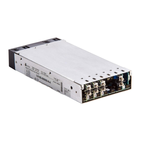
- Page 1 1800W Intelligent Modular Power Supply 1800W output Power Digital Communications and Control Excelsys Technologies Ltd Latest Industrial & Medical Approvals An Advanced Energy Company Aug 2018...
-
Page 2: Table Of Contents
Table of Contents Section 1: Overview of CoolX1800 ......................3 Section 2: Installation Considerations ....................4 Section 3: Configuration Considerations ....................5 Section 4: Theory of Operation ......................6 Section 5: Configuration (and Reconfiguration) ..................8 Section 6: CoolMod Operation....................... 9 Section 7: CoolMod Signals ........................ -
Page 3: Section 1: Overview Of Coolx1800
IEC60601-1 3rd edition & IEC60601-1-2 4th edition (EMC) for medical applications. The CoolX1800 can be populated with up to 6 CoolMods, providing up to 12 isolated DC outputs ranging from 2.5V to 58.0V. Continuing the Excelsys tradition of flexibility, the CoolX1800 is completely user and field configurable. -
Page 4: Section 2: Installation Considerations
The chassis comes with four mounting points on the base and two on each side. Maximum allowable torque for mounting screws is 2Nm and maximum allowable penetration depth is 2mm. Alternatively, DIN-Rail mounting is also possible using the Excelsys Din-Rail mounting bracket. -
Page 5: Section 3: Configuration Considerations
• If a CmE or CmF module is to be configured in the CoolX1800, it must be used in Slot 6. This leaves Slot 1, Slot 2 and Slot 3 free for other modules or another CmE or CmF module. -
Page 6: Section 4: Theory Of Operation
Section 4: Theory of Operation The CoolX platforms are comprised of an appropriate CoolPac and a selection of CoolMod DC output modules selected to deliver the exact volts and amps requirements of the system designer. An operational block diagram is shown above. The CoolPac is made up of an off-line single-phase AC front end, EMI filter, and customer interface and associated housekeeping circuits. - Page 7 A configured CoolX has the following galvanic isolation barriers. Isolation Barrier Type Withstand Voltage Input to Output Reinforced (2 x MOPP) 4000VAC Input to Case (GND) Basic (1 x MOPP) 1850VAC Output to Case (GND) Basic (1 x MOPP) 1850VAC Output to Output Basic (1 x MOPP) 1850VAC...
-
Page 8: Section 5: Configuration (And Reconfiguration)
Section 5: Configuration (and Reconfiguration) CoolMods may be easily added, replaced, or moved by plugging the modules in or out of the CoolPac chassis. Prior to removing or installing a CoolMod, remove input power from the CoolPac and wait 4 minutes. Failure to do so can result in personal injury and/or damage to the supply. -
Page 9: Section 6: Coolmod Operation
Section 6: CoolMod Operation The CoolX has been designed to allow maximum flexibility in meeting the unique requirements of system designers. The inherent flexibility resulting from modular concepts allows users to configure solutions with multiple outputs that can be individually controlled. There are 8 CoolMods which provide discrete isolated DC outputs according to the CoolMod Summary Specifications table below. - Page 10 On Board Potentiometer (All Modules) Simply adjust the output voltage to the required level using the multi-turn trim pot present on the CoolMod. Remote Voltage Adjustment (CmA-F Modules) Remote Voltage adjustment is not available on the CmG or CmH CoolMods. The output voltage of the CoolMod can be set by applying a control voltage Vtrim across the Output Signal Connector pins Vtrim (Pin 6) and Common (Pin 1).
- Page 11 Voltage control via PMBus (CmA-F Modules) Please see the CoolX PMBus Manual for further details. Important note regarding Vtrim and adjusting output voltage using PMBus Vtrim and PMBus control can only adjust the output voltage downwards from the on-board potentiometer set voltage. For example, if a CoolMod CmC is set by the potentiometer to 24.0V, Vtrim and PMBus will only be able to dynamically adjust/set the output voltage between the ranges of 15.0V to 24.0V.
- Page 12 Straight line Current Limit (CmA-D Modules) The current limit of the CoolMod can bet set by applying a control voltage Itrim across the Output Signal Connector pins Itrim (Pin 5) and Common (Pin 1). The Itrim voltage required for the users desired current limit can be calculated using the following formula and table. ��...
- Page 13 The current limit of the CoolMod can bet set by placing a resistor Rtrim across the Output Signal Connector pins Itrim (Pin 5) and Common (Pin 1). The Rtrim resistance required for the users desired output current limit can be calculated using the following formula along with the same table used to calculate Itrim.
- Page 14 The Fixed OVP level is fixed relative to Vmax, and will activate between 103-170% of the maximum output voltage. The Fixed OVP will turn off all outputs of the CoolX1800 and, like the tracking OVP, will hiccup all outputs until the fault condition is removed.
- Page 15 When Vset is less than or equal to Vnom, current limit is employed at the current limit set point. For CmA-D modules, if Vset is greater than Vnom, an intelligent power limit method is employed to ensure that the CoolMod does not exceed its power rating. E.g.
- Page 16 Excelsys recommends the use of an x1 probe with the ground sheath of the probe tip used for ground connection. In some applications, further erroneous readings may result from Common Mode currents.
- Page 17 Parallel Connection for CoolMods To achieve increased current capacity, simply parallel outputs using the standard parallel links. Excelsys passive current sharing ensures that current hogging is not possible. To Parallel Connect CoolMods CmA-D • Turn on current sharing by adding a jumper on J4 Connector.
- Page 18 To Parallel Connect CmE-F CoolMods • Turn on module current sharing by adding a jumper on J1017 Connector located on the Comms Board of the CoolX1800. Jumper: Harwin – M22-1900005, 2 x 1 2.00 mm Pitch • Attach the positive and negative parallel links to the outputs of the modules. (There...
- Page 19 Note: CmG-H module outputs should not be paralleled. Since all Coolmod signals are isolated from the Coolmod outputs, when CoolMods are connected in series or parallel, all CoolMod analog control functions (Vtrim, Itrim, Enable/Inhibit) can be implemented by paralleling the appropriate signal pins of each CoolMod and providing a single control signal, i.e.
-
Page 20: Section 7: Coolmod Signals
Section 7: CoolMod Signals CoolMod Enable/Inhibit Each CoolMod may be enabled/inhibited by means of a logic level signal applied to the enable input on Output Signal Connector J1001-J1006, Pin 4 (Positive), Pin 1 or 3 (Negative). The input has a 1K ohm series resistor and a 100nF filtering capacitor to filter noise on this signal. The input voltage must be limited to no greater than 5 volts. - Page 21 The maximum collector voltage is 5V, and the maximum collector current is 12mA. Refer to the implementation circuit and Table of logics below for recommendations for driving Logic Level circuits with open collector signal outputs. Table of Logics Auxiliary Voltage Logic Voltage Vhigh Vlow...
- Page 22 When there is a voltage present on the output pins of the channel the transistor of the optocoupler is turned ON. If the output drops out of regulation the transistor turns OFF. To monitor the Power Good of a channel, +PG should be pulled up to a reference voltage with a pull-up resistor.
-
Page 23: Section 8: Coolpac Operation
Section 8: CoolPac Operation The CoolPac provides the front end input power to the CoolMod. The CoolPac operates of 85- 264VAC, 47-440Hz and can withstand 300VAC input voltage for up to 5 secs. The CoolPac can also operate off DC inputs of 125VDC-300VDC. There are two CoolPac versions. -
Page 24: Section 9: Global Signals
Section 9: Global Signals The CoolX Global Signals are available on the J1007 System Signal Connector. *NU: Not Used or No Connection AC Fail The CoolPac AC Fail Signal indicates that the input voltage has failed or has dropped below 70VAC. - Page 25 Global Inhibit/Enable (CONTROL) All CoolMod outputs may be enabled/inhibited simultaneously by means of an appropriate signal applied to the CONTROL input on J1007, between Pin 3 (Control) and Pin 1 (Common). Under normal conditions Pin 3 is pulled to 5V internally (logic high) and all modules are enabled.
- Page 26 Over Temperature Protection The CoolX monitors internal temperatures on the power supply to ensure that component temperatures do not exceed their ratings. The OTP warning signal an unbiased open collector signal that is available on the J1007 System Signal Connector via the collector on Pin 7 and the emitter on Pin 1 (Common).
- Page 27 CoolPac Open Collector Driving Common Logic Levels Each CoolPac logic output (Global Power Good, AC Fail, and OTP) is an Open Collector driver to Common with a 390Ω resistor in series with the collector for current limiting. These outputs can safely sink up to 12mA and have a breakdown voltage of greater than 25V. Pull up resistors should be chosen to keep the sink current under 12mA.
-
Page 28: Section 10: Power Ratings
Temperature Derating and Input Voltage Derating. The CoolX1800 will deliver 100% rated power from -20 to 40degC and 50% output power up at 70°C. Input Voltage Derating and Temperature Derating curves are shown below. -
Page 30: Section 11: Mechanical Information
The CoolX mechanical outline is shown below. Full 3D and STEP files can be downloaded from www.excelsys.com or alternatively contact Excelsys for details. Connectors: Input Connectors (CoolPac) AC mains is applied to the CoolX via the 3 Screw Terminal Block or the optional IEC320 inlet... - Page 31 Auxiliary Bias Supply Voltage The Auxiliary Bias supply (always ON) of 12V/1.97A or 5V/4.7A (optional) is provided on J1 connector. J1 Auxiliary Output Connector Molex 104188-0210 Output Power and Sense Connectors (CmA-F) Each CoolMod (CmA-D and CmE-F) has Power Terminals (J1 and J2) and a Remote Sense Connector (J3).
- Page 32 Output Power and Signal Connectors (CmG-H) The CmG and CmH modules have a Dual Power Terminal J2 and a Signal Connector J1. J1 CmG/CmH Signal Connector: 8-way Molex: 87833-0831 Mating Connector J1: Locking Molex: 51110-0860, Non-Locking Molex: 51110-0850; Locking and Polarizing: 51110-856 Crimp Terminal: Molex p/n 50394 J2 Power Terminal: Camden: CTB9350/4A...
- Page 33 Global System Signal Connector The System Signal Connector contains all the Global signals including AC Fail, Power Good, and Over-Temperature Alarm. J1007 System Signal Connector 8-way Molex: 87833-0831 Mating Connector J1007: Locking Molex: 51110-0860, Non-Locking Molex: 51110-0850; Locking and Polarizing Molex: 51110-0856 Crimp Terminal: Molex p/n 50394...
- Page 34 The CoolX can be mounted in the system via the 2 mounting holes on each side of the CoolX. See mechanical drawings for mounting hole positions. Use M3 mounting screws and ensure that maximum screw penetration from base does not exceed 2mm. DIN-Rail Mounting The CoolX can be mounted on the Excelsys DIN-Rail mounting bracket (Z744).
-
Page 35: Section 12: Coolx Nomenclature
Section 12: CoolX Nomenclature The CoolX user configurable power supply combines feature rich AC input front-ends (CoolPacs) with plug-in DC output modules (CoolMods). The plug and play system allows system designers to define and build ‘instant’ custom power solutions. S/M (Standard of Medical CoolPac) S= Standard IEC60950 2 Edition and IEC62368-1 M= Medical IEC60601-1 3... - Page 36 Selecting & Ordering Configured CoolX Configured CoolX power supplies may be specified and ordered using the part numbering system shown. At our configuration centre, we will assemble the CoolX as specified by you accounting for slot preferences and also for preferred settings (Voltage/Series/Parallel etc.), and also incorporating any Options required.
-
Page 37: Section 13: Reliability
To ensure that these early failures do not happen while in the possession of the user, Excelsys carries out a full burn-in on each unit, designed to ensure that all these early failures are detected at Excelsys. After this period, the power supplies fail very rarely, and the failure rate during this period is fairly constant. - Page 38 According to published research, the commencement of this chemical reaction can occur after a two year period of an unpowered unit, and as such Excelsys recommends that the maximum shelf life for our platform designs is two years.
-
Page 39: Section 14: Safety Approvals
Section 14: Safety Approvals CoolX is compliant with the latest Safety approvals, and is also compliant with future changes in safety standards for Medical, Industrial and ITE equipment. CX18S is certified to IEC60950 2 Edition and is compliant with the upcoming IEC62368-1 Safety approvals. -
Page 40: Section 15: Emc Characteristics
EMC directive, since performance is critically dependent on the final system configuration. System compliance with the EMC directive is facilitated by Excelsys products compliance with several of the requirements as outlined in the following paragraphs. - Page 41 >180VAC. Guidelines for Optimal EMC Performance All Excelsys products are designed to comply with European Normative limits (EN) for conducted and radiated emissions and immunity when correctly installed in a system. See performance levels attained above. However, power supply compliance with these limits is not a guarantee of system compliance.
-
Page 42: Section 16: Environmental Parameters
Section 16: Environmental Parameters The CoolX series are designed for the following parameters • Material Group IIIb, Pollution Degree 2 • Installation Category 2 • Class I • Indoor use (installed, accessible to Service Engineers only). • Altitude: -155 metres to +5000 metres from sea level. •... - Page 43 Additional Information Additional information such as Application Note, White Papers, Safety Certificates etc. are available at www.excelsys.com. Alternatively please do not hesitate to contact Excelsys if you have any further questions or need additional information. For Technical Support email support@excelsys.com Sales Enquiries for North America email salesusa@excelsys.com...
-
Page 44: Appendix 1: Detailed Output Specifications
Maximum capacitive load of the module to (mF) ensure monotonic startup (with no additional load applied) *Full Dynamic Specifications of the CmB module may not be met at full load when the CmB module is trimmed above 13 V in the CoolX1800... - Page 45 Ripple and Noise Nom / Parameter Description Module Typical Output Ripple (mV) Amplitude of ripple measured at nominal voltage and at 20 MHz Bandwidth Frequency of output ripple (all modules Output Ripple All Mods synchronised to same frequency) Frequency (kHz) Regulation Nominal Parameter...
- Page 46 Measured over 5 hiccup cycles Current Limit (A) 1.25 Power Limit (W) Voltage Foldback into Hiccup, Auto-Recovery Overvoltage CoolX600: Shutdown, Latch-off Protection (V) CoolX1800: Shutdown, Auto-Recovery 19.8 62.2 Sense Lead Shutdown, Auto-Recovery All Mods Protection (V) Start-Up / Shut-Down Nom /...
- Page 47 Enable / Disable Nom / Parameter Description Module Typical Enable Delay (ms) Time from application of Enable signal to All Mods Output Voltage regulation (t1) Rise Time (ms) Measured from 10 – 90% of Vout All Mods Disable Delay (ms) Time from application of Disable signal to All Mods loss of Output Voltage Regulation (t2)
- Page 48 Transient Response Nominal Parameter Description Module Minimum Maximum / Typical Transient Measured during 25 – 75% and 75 – 25% Response, Voltage Step Load Changes Deviation (V) Transient Measured during 25 – 75% and 75 – 25% Response, Recovery Step Load Changes All Mods Time (us) Transient...
- Page 49 PMBus Communications Standard modules can be monitored and controlled with the following PMBus Commands (for further details see the PMBUS Manual available for download from the Excelsys website. Specification Description READ_VOUT (0x8B) The READ_VOUT command is used to return the output...
- Page 50 Bulk Modules (CmE-CmF) Ratings Nom / Parameter Description Module Typical Output Voltage (V) Output voltage range for which the module 23.4* 25.2 is rated for operation 45.6 50.4 Factory Setting Maximum deviation from target output Accuracy (mV) voltage setting when CoolX is initially configured.
- Page 51 Ripple and Noise Nom / Parameter Description Module Typical Output Ripple (mV) Amplitude of ripple measured at nominal voltage and at 20 MHz Bandwidth Frequency of output ripple (all modules Output Ripple All Mods synchronised to same frequency) Frequency (kHz) Regulation Nominal Parameter...
- Page 52 (Arms) Power Limit (A) Hiccup, Auto Recovery 1080 1080 Overvoltage CoolX600: Shutdown, Latching 30.5 31.5 Protection (V) CoolX1800: Shutdown, Auto-Recovery 45.5 Sense Lead CoolX600: Shutdown, Latching All Mods Protection (V) CoolX1800: Shutdown, Auto-Recovery Start-Up / Shut-Down Nom / Parameter Description...
- Page 53 Enable / Disable Nom / Parameter Description Module Typical Enable Delay (ms) Time from application of Enable signal to All Mods Output Voltage regulation (t1) Rise Time (ms) Measured from 10 – 90% of Vout All Mods Disable Delay (ms) Time from application of Disable signal to All Mods loss of Output Voltage Regulation (t2)
- Page 54 Transient Response Nominal Parameter Description Module Minimum Maximum / Typical Transient Measured during 25 – 75% and 75 – 25% Response, Voltage Step Load Changes Deviation (V) Transient Measured during 25 – 75% and 75 – 25% Response, Recovery Step Load Changes All Mods 1000 Time (us)
- Page 55 PMBus Communications Bulk modules can be monitored and controlled with the following PMBus Commands (for further details see the PMBUS Manual available for download from the Excelsys website. Specification Description READ_VOUT (0x8B) The READ_VOUT command is used to return the output...
- Page 56 Dual Modules (CmG-CmH) Ratings Nom / Parameter Description Module Typical Output Voltage (V) Output voltage range for which the module CmG (V1+V2) channel is rated for operation CmH (V1) CmH (V2) Factory Setting Maximum deviation from target output Accuracy (mV) voltage setting when CoolX is initially All Mods configured.
- Page 57 Ripple and Noise Nom / Parameter Description Module Typical Output Ripple (mV) Amplitude of ripple measured at nominal CmG (V1+V2) voltage and at 20 MHz Bandwidth CmH (V1) CmH (V2) Frequency of output ripple, all modules Output Ripple All Mods synchronised to same frequency Frequency (kHz) Regulation...
- Page 58 Measured over 5 hiccup cycles CmG (V1+V2) Current Limit (A) CmH (V1) CmH (V2) Overvoltage CoolX600: Shutdown, Latching CmG (V1+V2) Protection (V) CoolX1800: Shutdown, Auto-Recovery CmH (V1) CmH (V2) Start-Up / Shut-Down Nom / Parameter Description Module Typical Turn-On Delay (ms)
- Page 59 Enable / Disable Nom / Parameter Description Module Typical Enable Delay (ms) Time from application of Enable signal to All Mods Output Voltage regulation (t1) Rise Time (ms) Measured from 10 – 90% of Vout All Mods Disable Delay (ms) Time from application of Disable signal to All Mods loss of Output Voltage Regulation (t2)
- Page 60 All Mods Module (Vac) PMBus Communications Standard modules can be monitored and controlled with the following PMBus Commands (for further details see the PMBUS Manual available for download from the Excelsys website. Specification Description PAGE (0x00) The PAGE command is used to select which of the modules subsequent commands are to be applied to.
- Page 61 Auxiliary Output Ratings Nom / Parameter Description Option Typical Output Voltage (V) Output voltage of the Auxiliary Output 4.85 5.15 12 V 11.6 12.4 Output Current (A) Maximum output current for which the Auxiliary Output is rated for operation 12 V Output Power (W) Maximum output power for which the 23.5...
- Page 62 Protective Limits Nom / Parameter Description Option Typical Current Limit (A) Hiccup. Auto-Recovery 12 V Short-Circuit Measured over 5 hiccup cycles Current Limit (Arms) 12 V Power Limit (W) Hiccup, Auto-Recovery 12 V 27.6 33.6 Galvanic Isolation Nom / Parameter Description Option Typical...
-
Page 63: Appendix 2: Thermal Derating
Appendix 2: Thermal Derating CoolX600 Test Condition Derating Convection Cooling Only Applies to CoolX600 and all CoolX Modules fitted in the CoolX600 Horizontal Mounting: Derate by 1.67%/ᵒC above 40 ᵒC ambient Vertical Mounting: Derate by 1.88%/ᵒC above 45 ᵒC ambient Test Condition Derating Conduction Cooling... - Page 64 1.67 m/s Linear Airflow: Derate by 5%/ᵒC above 70 ᵒC ambient CoolX1800 Test Condition Derating Normal Operation Applies to CoolX1800 and all CoolX Modules fitted in CoolX1800 Derate by 2.5%/ᵒC above 50 ᵒC ambient Max ambient operating temperature for a...
-
Page 65: Appendix 3: Analog Communications
Appendix 3: Analog Communications The output characteristics of standard modules can also be monitored and controlled with analog signals via the J100x connectors. Remote Voltage Setting (Using External Voltage) Available On: Standard Modules (CmA-CmD), Bulk Modules (CmE-CmF) The output voltage of the module can be set by applying a control voltage Vtrim across the Output Signal Connector (J100x) pins Vtrim (Pin 6) and Common (Pin 1 or Pin 3). - Page 66 47000(�� − ��) ������ �� ���������� �� + 5�� − �� ������ Where: Module 2.43 1.59 5.85 3.84 13.82 26.13 13.2 22.45 1.19 43.06 0.28 Please note that the upper range of remote trimmable voltage is limited by the potentiometer setting. Remote Current Limit Setting (Using External Voltage) Available On: Standard Modules (CmA-CmD) The current limit of the CoolMod can bet set by applying a control voltage Itrim across the Output Signal Connector (J100x)
- Page 67 Comms board between slot 2 and slot 3) are shorted with a jumper, and a logic low signal is applied between the CONTROL pin of J100x (Pin 3) and Common (Pin 1) – where J100x is J1005 for the CoolX600 and J1007 for the CoolX1800. Now when Pin 4 is HIGH, the module is disabled, and pulling Pin 4 to Common will enable the module.
- Page 68 Channel Enable / Disable Available On: Dual Modules (CmG-H) Each individual channel of the Dual Module may be enabled/inhibited by means of a signal applied to the Inhibit pins on the Module Signal Connector J1. When the Inhibit pins are floating, or when the +Inhibit pin is tied to the -Inhibit pin, the channel is enabled.
- Page 69 When the output voltage is within 10% of Vset the transistor is turned ON. If the output drops out of regulation the transistor turns OFF. This can be used for power sequencing in many applications (enabling another CoolMod output when the first output is within regulation, as well as driving external circuitry.
-
Page 70: Appendix 4: Mechanical Drawings
Appendix 4: Mechanical Drawings CoolX1800 (1 x Bulk Module, 1 x Dual Module, 2 x Standards Modules) - Page 71 CoolX1800 (2 x Bulk Modules)
- Page 72 CoolX1800 – (6 x Standard Modules)
- Page 73 CoolMod Operation Nomenclature CoolMod Signals CoolPac Operation Current Limit Adjustment (CmA-CmD) Foldback Open Collector Driving Common Logic Levels Straight Line Output Specifications Overview of CoolX1800 EMC Characteristics EMC Directive 2004/108/EC Paralleling Enable / Disable CmA-CmD CmA-CmD CmE-CmF CmE-CmF PMBus Communications...
- Page 74 CmA-CmD Series Connection (CmA-CmD and CmF) CmE-CmF Shelf Life of Power Supplies CmG-CmH Start-Up / Shut-Down Regulation CmA-CmD Auxiliary CmE-CmF CmA-CmD CmG-CmH CmE-CmF CmG-CmH Reliability Remote Sense (CmA-CmF) Theory of Operation Ripple and Noise Thermal Derating Auxiliary Transient Response CmA-CmD CmA-CmD CmE-CmF CmE-CmF...
Need help?
Do you have a question about the CoolX1800 and is the answer not in the manual?
Questions and answers