Table of Contents
Advertisement
Quick Links
Advertisement
Table of Contents

Subscribe to Our Youtube Channel
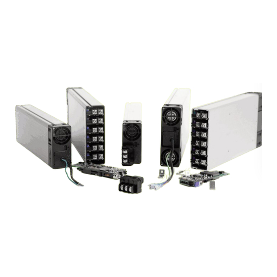
Summary of Contents for Excelsys ultimod
- Page 1 Designer Manual...
-
Page 2: Installation Considerations
• Always fill all output slots of the UltiMod. If a slot is not filled with a powerMod, it should be filled with an Empty Slot Cover The plug-together architecture facilitates ‘instant’ custom power (part numbers XB1, XB2 or XB3). -
Page 3: Theory Of Operation
EMI/RFI twisted pair to minimise inductance. emission. • Wait 4 minutes after shutting off power before inserting or removing powerMods. At initial power-up, the UltiMod outputs are disabled to eliminate • UltiMod assemblies have user serviceable inrush current and a low-power flyback converter operating with components. - Page 4 See Section 4.6 for details. Section 4.6 powerMod Operation The UltiMod has been designed to allow maximum flexibility in meeting the unique requirements of individual users. inherent flexibility resulting from modularity concepts is further Remote Output Voltage Adjustment of powerMods enhanced by this flexibility.
- Page 5 UltiMod Designer Manual Output powerMod Summary Specifications Visit the UltiMod Online Configurator to get the best recommendation for your application at www.excelsys.com/xgen_configurator/configure.html diagrams and Foldback Programmable Current Limit diagram. The default current limit characteristic is Straight Line Current = 1000V [(4.275 +Vp(1.96-4Vp)] -K(0.1Vp+0.051) (3)
- Page 6 F = 0.0468 for XgH F = 0.0468 for XgH CF = 1.043 for XgH CF = 1.042 for XgH = 36A for XgH = 36A for XgH = 20 = 55.5% (less than 85%) = 20 = 55.5% (less than 85%) www.excelsys.com...
- Page 7 Each powerMod has a number of levels of protection in order to by using resistors in the sense leads (Positive sense lead: R ensure that UltiMod is not damaged if used in overload 100ohm , Negative sense lead: R =10ohm ), together with local conditions.
- Page 8 Section 4.7 Mechanical Section Input Connectors The UltiMod series has a variety of input connector options to ease system integration. These include IEC, Input cables (3- wire) and IEC to Screw Terminal Adaptor. Standard cable length 300mm, please...
- Page 9 UltiMod Designer Manual Remote Inhibit/Enable of Output Output Signals and Power Connector Pinout Output Signals and Power Connector Pinout Module (XgA to XgD) (XgG to XgL) (XgE) (XgF) (Type A) (Type B) not used +Sense not used - pg (V2)
- Page 10 UltiMod Designer Manual DIP Switch Option for XgG to XgL powerMod Power Good Signal (XgG - XgL) powerMods can be configured to be normally ON or normally Each powerMod contains an internal comparator which OFF by appropriate setting of the DIP switch on the powerMod.
- Page 11 These parts have been tested on 3 axes, for a total of 300hours at 1.67g’s rms. All UltiMod power supplies can withstand. Shock >60G, per MIL-STD 810G. Global Enable Using Bias Supply Voltage www.excelsys.com...
-
Page 12: Power Ratings
Section 4.11 powerPac Options Reverse Fan (Option 02) The UltiMod is available with reverse air flow direction. This is ideal to expel air from the system and works particularly well withthe internal fan cooling built into the overall system. Contact factory for details. -
Page 13: Safety Approvals
In this manner, MTBF can be calculated at any temperature. Indoor use (installed, accessible to Service Engineers only). The UltiMod series has the following failure rates at 40°C and Altitude: -155 metres to +2000 metres from sea level. full load, based on Telecordia SR-332 standard. - Page 14 EN55022 Class B, without the need for external filtering. IMMUNITY Configuration Example 1: UX4CGD0-D4 contains; The UltiMod series has been designed to meet, and tested to, UX4 powerPac: 600W 4-slot chassis, Standard module the immunity specifications outlined below: settings: Slot 1: XgC: 36V/5.6A...
-
Page 15: Technical Resources
In To contact one of our team please e-mail conjunction with the UltiMod Designers’ Manual, and Application support@excelsys.com or telephone: Notes, we also prepare White Papers on topics that are relevant to system designers.


Need help?
Do you have a question about the ultimod and is the answer not in the manual?
Questions and answers