Carrier Puron 38TZA Installation And Start-Up Instructions Manual
12, 13, 14 seer split-system air conditioners
Hide thumbs
Also See for Puron 38TZA:
- Manual (9 pages) ,
- Product data (36 pages) ,
- Product data (25 pages)
Advertisement
Visit www.carrier.com
Installation and Start-Up Instructions
NOTE: Read the entire instruction manual before starting the
installation.
This symbol → indicates a change since the last issue.
SAFETY CONSIDERATIONS
Improper installation, adjustment, alteration, service, maintenance,
or use can cause explosion, fire, electrical shock, or other
conditions which may cause death, personal injury, or property
damage. Consult a qualified installer, service agency, or your
distributor or branch for information or assistance. The qualified
installer or agency must use factory-authorized kits or accessories
when modifying this product. Refer to the individual instructions
packaged with the kits or accessories when installing.
Follow all safety codes. Wear safety glasses, protective clothing,
and work gloves. Use quenching cloth for brazing operations.
Have fire extinguisher available. Read these instructions thor-
oughly and follow all warnings or cautions included in literature
and attached to the unit. Consult local building codes and National
Electrical Code (NEC) for special requirements.
Recognize safety information. This is the safety-alert symbol
When you see this symbol on the unit and in instructions or
manuals, be alert to the potential for personal injury.
Understand these signal words; DANGER, WARNING, and
CAUTION. These words are used with the safety-alert symbol.
DANGER identifies the most serious hazards which will result in
severe personal injury or death. WARNING signifies hazards
which could result in personal injury or death. CAUTION is used
to identify unsafe practices which would result in minor personal
injury or product and property damage.
Before installing, modifying, or servicing system, main elec-
trical disconnect switch must be in the OFF position. There
may be more than 1 disconnect switch. Lock out and tag
switch with a suitable warning label. Electrical shock can
cause personal injury or death.
Puron™ systems operate at higher pressures than standard
R-22 systems. Do not use R-22 service equipment or com-
ponents on Puron™ equipment.
INSTALLATION RECOMMENDATIONS
NOTE: In some cases noise in the living area has been traced to
gas pulsations from improper installation of equipment.
1. Locate unit away from windows, patios, decks, etc. where unit
operation sound may disturb customer.
2. Ensure that vapor and liquid tube diameters are appropriate for
unit capacity.
3. Run refrigerant tubes as directly as possible by avoiding
unnecessary turns and bends.
Manufacturer reserves the right to discontinue, or change at any time, specifications or designs without notice and without incurring obligations.
Book 1 4
PC 101
Catalog No. 563-737
Tab 3a 2a
12, 13, 14 SEER Split-System
Air Conditioners with Puron™
→
.
4. Leave some slack between structure and unit to absorb
vibration.
5. When passing refrigerant tubes through the wall, seal opening
with RTV or other pliable silicon-based caulk. (See Fig. 2.)
6. Avoid direct tubing contact with water pipes, duct work, floor
joists, wall studs, floors, and walls.
7. Do not suspend refrigerant tubing from joists and studs with a
rigid wire or strap which comes in direct contact with tubing.
(See Fig. 2.)
8. Ensure that tubing insulation is pliable and completely sur-
rounds vapor tube.
9. When necessary, use hanger straps which are 1 in. wide and
conform to shape of tubing insulation. (See Fig. 2.)
10. Isolate hanger straps from insulation by using metal sleeves
bent to conform to shape of insulation.
When outdoor unit is connected to factory-approved indoor unit,
outdoor unit contains system refrigerant charge for operation with
ARI rated indoor unit with highest sales volume when connected
by 15 ft of field-supplied or factory accessory tubing. For proper
unit operation, check refrigerant charge using charging informa-
tion located on control box cover and/or in the Check Charge
section of this instruction.
IMPORTANT: Maximum liquid-line size is 3/8-in. OD for all
residential applications including long line.
IMPORTANT: Always install the factory-supplied liquid-line fil-
ter drier. If replacing the filter drier, refer to Product Data Digest
for appropriate part number. Obtain replacement filter driers from
your distributor or branch.
Printed in U.S.A.
Form 38T-8SI
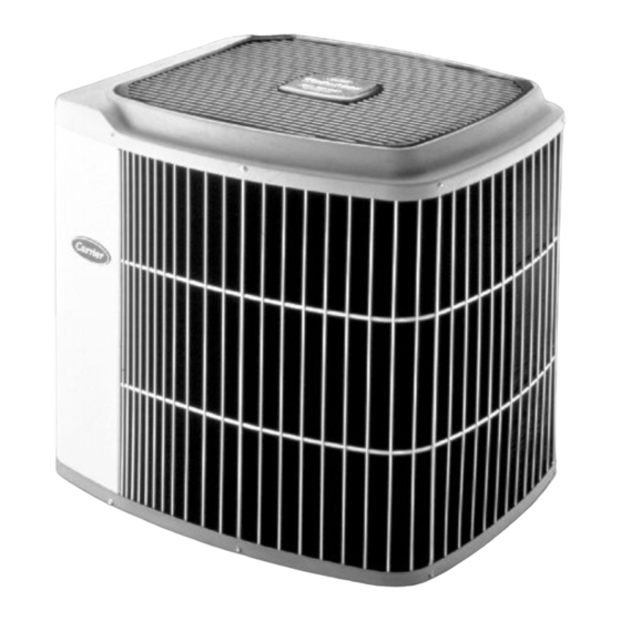
38TZA, TXA, TSA
Fig. 1
Pg 1
10-98
Replaces: 38T-7SI
A98516
Advertisement
Table of Contents

Related Manuals for Carrier Puron 38TZA


Summary of Contents for Carrier Puron 38TZA
- Page 1 38TZA, TXA, TSA 12, 13, 14 SEER Split-System Air Conditioners with Puron™ Visit www.carrier.com Installation and Start-Up Instructions NOTE: Read the entire instruction manual before starting the installation. This symbol → indicates a change since the last issue. SAFETY CONSIDERATIONS...
-
Page 2: Installation
3 /8 - NOTE: Avoid contact between tubing and structure IN. DIA TIEDOWN KNOCKOUTS IN BASEPAN (2) PLACES OUTDOOR WALL INDOOR WALL CAULK LIQUID TUBE VAPOR TUBE INSULATION THROUGH THE WALL ″ VIEW FROM TOP JOIST HANGER STRAP A97548 (AROUND VAPOR Dimensions (In.) INSULATION TUBE ONLY) -
Page 3: Refrigerant Tubing
Step 6—Install TXV (38TSA-Standard; 38TXA/38TZA- Optional) Do not leave system open to atmosphere any longer than NOTE: ALL 38TSA UNITS MUST BE INSTALLED WITH A minimum required for installation. POE oil in compressor is TXV—NO EXCEPTIONS! extremely susceptible to moisture absorption. Always keep The thermostatic expansion valve is specifically designed to ends of tubing sealed during installation. - Page 4 Table 1—Refrigerant Connections and Recommended Liquid and Vapor Tube Diameters (In.) LIQUID VAPOR VAPOR (LONG LINE) UNIT SIZE Connection Diameter Tube Diameter Connection Diameter Tube Diameter Connection Diameter Tube Diameter 030, 036 042, 048 1-1/8 1-1/8 1-1/8 NOTES: 1. Tube diameters are for lengths up to 50 ft. For tubing lengths greater than 50 ft, consult the Application Guideline and Service Manual for Residential Split-System Air Conditioners and Heat Pumps Using Puron™...
- Page 5 FINAL TUBING CHECK 5000 IMPORTANT: Check to be certain factory tubing on both indoor 4500 and outdoor unit has not shifted during shipment. Ensure tubes are 4000 not rubbing against each other or any sheet metal. Pay close LEAK IN 3500 attention to feeder tubes, making sure wire ties on feeder tubes are SYSTEM...
-
Page 6: Connect Control Wiring
CONNECT CONTROL WIRING Route 24-v control wires through control wiring grommet and Do not vent refrigerant to atmosphere. Recover during system connect leads to control wiring. (See Fig. 9.) repair or final unit disposal. Use No. 18 AWG color-coded, insulated (35°C minimum) wire. If thermostat is located more than 100 ft from unit, as measured Follow these steps to properly start up the system: along the control voltage wires, use No. - Page 7 COOLING ONLY PROCEDURE Table 3—Required Liquid-Line Temperature (°F) Units with Cooling Mode TXV REQUIRED SUBCOOLING LIQUID TEMPERATURE PRESSURE AT Units installed with cooling mode TXV require charging by the (°F) SERVICE VALVE subcooling method. (PSIG) 1. Operate unit a minimum of 10 minutes before checking charge.
-
Page 8: Care And Maintenance
Table 4—Superheat Charging OUTDOOR EVAPORATOR ENTERING AIR TEMPERATURE (°F WB) TEMP (°F) — — — — — — — — — — — — — — — — — — — — — — — — — — — — —... - Page 9 PURON™ —QUICK REFERENCE GUIDE Puron™ refrigerant operates at 50-70 percent higher pressures than R-22. Be sure that servicing equipment and replacement • components are designed to operate with R-410A. Puron™ refrigerant cylinders are rose colored. • Puron™ refrigerant cylinders have a dip tube which allows liquid to flow out of cylinder in upright position. •...
- Page 10 CARRIER FA, FB, FC, NON-PROGRAMMABLE FD, FF, FX THERMOSTAT CARRIER FAN COIL CONDITIONER MODEL AC NON-PROGRAMMABLE SINGLE-STAGE THERMOSTAT FURNACE CONDITIONER MODEL AC 24 VAC HOT 24 VAC HOT 24 VAC COM 24 VAC COM NOTE 2 HEAT STAGE 1 W/W1...
- Page 11 A97592 NOTES: 1. CARRIER THERMOSTAT WIRING DIAGRAMS ARE ONLY ACCURATE FOR MODEL NUMBERS TSTAT _ _ _ _ _ _ _. 2. WIRING MUST CONFORM TO NEC OR LOCAL CODES. 3. SOME UNITS ARE EQUIPPED WITH PRESSURE SWITCH(ES), TEMPERATURE SWITCH, OR 5-MINUTE COMPRESSOR CYCLE PROTECTION.
-
Page 12: Service Training
[ ] Classroom Service Training A94328 Copyright 1998 CARRIER Corp. • 7310 W. Morris St. • Indianapolis, IN 46231 38t8si Manufacturer reserves the right to discontinue, or change at any time, specifications or designs without notice and without incurring obligations.
Need help?
Do you have a question about the Puron 38TZA and is the answer not in the manual?
Questions and answers