Table of Contents
Advertisement
575 Birch Street, Forestville, CT 06010
Phone (860) 584-9158 Fax (860) 584-2136
www.locknetics.com
101-2+
General Description............................................. 2
Technical Specifications.......................................2
Pre Installation Considerations............................ 3
Door/Frame Prep/Template Information...............4
Mechanical Installation........................................ 6
PC Board Layout and Features........................... 8
Anti Tamper Switch Information........................... 8
Dipswitch Settings................................................9
Terminal Layout/Description of Functions............10
101+/101-2+/101+DB Wiring Information............ 11
100CAB/TR80/TR81 Hook-up..............................12
Relock Time Delay............................................... 14
Nuisance Delay.................................................... 14
PLEASE READ ALL INSTRUCTIONS PRIOR TO INSTALLING THE ELECTROMAGNETIC LOCK.
IMPORTANT! This manual is intended to be kept for programming, maintenance,
and trouble shooting purposes. Do not dispose of this manual after installation.
Please present this manual to the facility manager upon completion of installation.
FORM 10111 Rev. C
101+
DELAYED EGRESS
MAGNETIC LOCKING SYSTEM
HANDLE THE EQUIPMENT CAREFULLY
ELECTROMAGNET OR THE ARMATURE MAY REDUCE LOCKING EFFICIENCY
101+ DELAYED EGRESS MAGNETIC LOCKING SYSTEM
INSTALLATION AND PROGRAMMING MANUAL
PUSH UNTIL ALARM SOUNDS.
DOOR WILL OPEN IN 15 SECONDS.
101+DB
Door Propped Delay(SEC)...................................14
Erasing Memory................................................... 14
"System 7" TouchEntry Key Programming.......... 15
Keypad Initialization............................................. 15
Definition of Code/TEK Functions/Defaults..........15
Keypad Manual Programming............................. 16
TouchEntry Key Manual Programming................ 18
TEP1/TEP2 Initialization...................................... 18
Error Codes..........................................................21
Trouble Shooting.................................................. 21
Maintenance.........................................................21
Overall Dimensions.............................................. 22
,
DAMAGING THE MATING SURFACES OF THE
1
.
04/11/2002
Advertisement
Table of Contents

Subscribe to Our Youtube Channel
Summary of Contents for Locknetics 101+
-
Page 1: Table Of Contents
Anti Tamper Switch Information......8 Keypad Manual Programming......16 Dipswitch Settings..........9 TouchEntry Key Manual Programming....18 Terminal Layout/Description of Functions....10 TEP1/TEP2 Initialization........18 101+/101-2+/101+DB Wiring Information.... 11 Output Audible/Visual/Alarm Indication Table..20 Monitoring(Alarm,DSM,MBS)/Control Wiring..11 Error Codes............21 100CAB/TR80/TR81 Hook-up......12 Trouble Shooting..........21 Relock Time Delay.......... -
Page 2: General Description
Locknetics manufactures fire rated mechanical latching devices. The electronically controlled 101+ series magnetic locks described in this manual share the same access control circuitry in all models. -
Page 3: Pre Installation Considerations
FRAME STRIKE JAM Frame conditions may require the use of filler plates and/or angle brackets. These items are available from Locknetics. In some cases it may be necessary to fabricate custom brackets or filler plates to make a secure installation. -
Page 4: Door/Frame Prep/Template Information
101+ DELAYED EGRESS MAGNETIC LOCKING SYSTEM INSTALLATION PROCEDURE 1. PREP DOOR AND FRAME (FOR STANDARD AND 101-2+ UNITS): The paper template is the preferable way to prepare the door and frame. If for any reason it is not available, use the dimensions shown below to mark the centerlines of the holes. - Page 5 MAGNETIC LOCKING SYSTEM 1. PREP DOOR AND FRAME (FOR 101+DB UNITS): The paper template is the preferable way to prepare the door and frame. If for any reason it is not available, use the dimensions shown below to mark the centerlines of the holes.
-
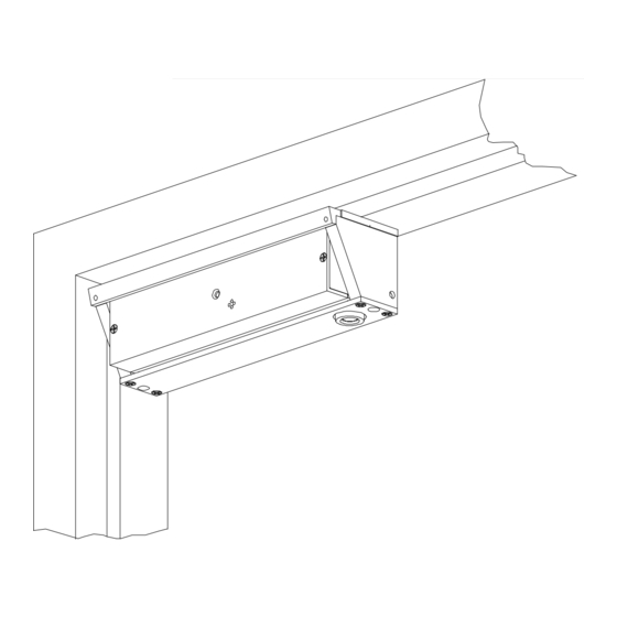
Page 6: Mechanical Installation
Note the direction of the door face. DOOR 101+DB 4. ALIGN PLATE TO ARMATURE USING PLASTIC ALIGNING TEMPLATE Close door. Push template/mounting plate assembly toward door until it comes against the armature leaving no gap. Tighten pan head screws completely. Mark the posi- tion of the mounting plate. - Page 7 101+ DELAYED EGRESS MAGNETIC LOCKING SYSTEM 5. SECURE MOUNTING PLATE Using the Mounting Plate as a template, drill the four (or eight for 101+DB) remaining mounting holes. If using #10 self-tapping, flat-head screws drill 5/32" dia. holes and drive four screws tight.
-
Page 8: Pc Board Layout And Features
The ATS option monitors the status of the electronics cover. When the cover is removed the unit goes into alarm. It must be reset by entering a valid code or TEK, or by entering a reset input into terminals 17 &18. (NOTE: on 101+DB and 101-2+ models the ATS on the slave unit is not wired directly into the PC board, rather, it has form C contacts with flying leads.) -
Page 9: Sw-4 Dipswitch Settings
101+ DELAYED EGRESS MAGNETIC LOCKING SYSTEM CONFIGURE FIRE ALARM INTERFACE DIPSWITCH (SW-1) FOR CORRECT TYPE OF INPUT. A dry contact is required. It can be normally open or normally closed. If no direct connection is to be made, configure the input for normally open (SW-1 to RIGHT). SW-1 FIRE ALARM INPUT: SW-1 TO RIGHT FOR N.O. -
Page 10: Terminal Layout/Description Of Functions
Apply 12 or 24 volts (AC or DC). The lock will adjust for input. IMPORTANT NOTES: a. PWM and double units (101-2+ and 101+DB can ONLY accept 12 volts) b. Polarity does not matter in this case FIRE ALARM INPUT: Apply a normally closed or normally open dry contact from fire panel or other emergency system. -
Page 11: 101+/101-2+/101+Db Wiring Information
The anti-tamper switch(ATS option) for the slave unit has flying leads whereas the ATS for the REQUIRED WIRING: master unit is wired directly to the PC board and will sound the on-board alarm. On 101+DB units, do not change or modify the factory-installed wiring. 101-2+ DOOR STATUS(DSM): 101-2+ LOCK STATUS (MBS): FORM 10111 Rev. -
Page 12: 100Cab/Tr80/Tr81 Hook-Up
WIRING OF LOCKNETICS KEYPADS/TOUCHENTRY KEY READERS Up to two Locknetics keypads or TouchEntry Key readers can be hooked up to a 101+ or 101-2+ system for access control and alarm reset input. Any keypad or TR83/TR84 hook up requires a 100CAB adapter cable. The three-wire 100CAB allows the keypad to be initialized to the lock or allows the TR83/TR84 to be properly connected. - Page 13 101+ DELAYED EGRESS MAGNETIC LOCKING SYSTEM NOTES: FORM 10111 Rev. C 04/11/2002...
-
Page 14: Relock Time Delay
101+ DELAYED EGRESS MAGNETIC LOCKING SYSTEM MANUAL PROGRAMMING OF TIME DELAYS: RELOCK TIME DELAY (factory default: 8 seconds) The amount of time the lock is de-energized after release by entering a valid code/TEK or Programmable 1-30 seconds. A. Set SW4 dipswitch #6 to OFF (if it is on). B. -
Page 15: Creating Master Tek (Computer Programming). 15 "System 7" Touchentry Key Programming
The Master TEK is used for initiating programming. It will not unlock the door. Unlike some other Locknetics products, creating a master TEK will not delete the factory default codes. They must be manually deleted. “SYSTEM 7” PROGRAMMING: This procedure will allow up to seven TouchEntry Keys to be programmed into a lock equipped with a TouchEntry Key reader of SelectEntry Keypad. -
Page 16: Keypad Manual Programming
101+ DELAYED EGRESS MAGNETIC LOCKING SYSTEM MANUAL PROGRAMMING - KEYPAD When manually programming the 101+ model lock, using a keypad, the keypad must first be initialized. It is a recommended that the factory default Master Code be changed. Doing so will delete all factory default codes and ensure the security of the system. After entering the Master code the LEDs on the keypad will flash. They will also flash each time that * is entered. - Page 17 101+ DELAYED EGRESS MAGNETIC LOCKING SYSTEM TO ADD TOGGLE CODES (Note that a three digit function code ‘131’ sets the function of the user code) UP TO 150 NEW CODES CAN BE ADDED BY RETURNING HERE. Master Code *...33*...131*...New Access Code (3-8 digits) * ...* (to end) TO ADD LOCKOUT CODES (Note that a three digit function code ‘115’...
-
Page 18: Touchentry Key Manual Programming
101+ DELAYED EGRESS MAGNETIC LOCKING SYSTEM MANUAL PROGRAMMING - TOUCHENTRY When manually programming the 101+ model lock for TouchEntry Keys, a programmer (either the TEP1 or TEP2) must first be initialized. Only one programmer can be initialized to a particular lock. A Master TEK must also be initialized at the same time as the programmer and will be used to enter the programming mode. See steps below. - Page 19 101+ DELAYED EGRESS MAGNETIC LOCKING SYSTEM TO ADD TOGGLE TEKs (Note that a three digit function code ’131’ sets the function of the user TEK) UP TO 150 NEW TEKs CAN BE ADDED BY RETURNING HERE. Master TEK ...33*...131*...New PIN(3-8 digits)*...New Toggle TEK ...* (to end) TO ADD LOCKOUT TEKs (Note that a three digit function code ’115’...
-
Page 20: Output Audible/Visual/Alarm Indication Table
101+ DELAYED EGRESS MAGNETIC LOCKING SYSTEM TABLE OF INDICATORS (LED/AUDIBLE) The table below is intended to provide all possible indications and states which can be encountered under normal operation. Note that some conditions or features are only available on certain models or when certain options are included. DESCRIPTION OF INDICATORS CONDITION LED INDICATOR... -
Page 21: Error Codes
101+ DELAYED EGRESS MAGNETIC LOCKING SYSTEM ERROR CODES: If an error is made while manually programming a lock, an error code indication will be indicated at the TouchEntry Key reader or keypad. The LED(s) will flash several times. Count the number of flashes and refer to the chart below for diagnosis. ERROR CODES NUMBER OF ERROR... -
Page 22: Overall Dimensions
101+ DELAYED EGRESS MAGNETIC LOCKING SYSTEM OVERALL DIMENSIONS 101+ 101-2+ 101+DB FORM 10111 Rev. C 04/11/2002...
Need help?
Do you have a question about the 101+ and is the answer not in the manual?
Questions and answers