Advertisement
Quick Links
Total solder points: 101
Difficulty level:
beginner 1o 2o 3þ 4o 5oadvanced
Features:
þ Suitable for most types of ventilators
þ Solid state switching with noise suppression
þ Can be connected to existing installation
þ LED function indication.
þ Can also be used without light as fan delay timer
Specifications :
• Power supply: 110 to 240Vac (50/60Hz)
• Maximum load: 200W (1A)
• Delay range: from 10sec. to 5min.
• Dimensions: 80x60mm (3,2" x 2,4")
ILLUSTRATED ASSEMBLY MANUAL
Fan timer
K8041
H8041IP-1
Advertisement

Subscribe to Our Youtube Channel
Summary of Contents for Velleman K8041
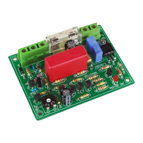
- Page 1 Total solder points: 101 Difficulty level: beginner 1o 2o 3þ 4o 5oadvanced Fan timer K8041 Features: þ Suitable for most types of ventilators þ Solid state switching with noise suppression þ Can be connected to existing installation þ LED function indication.
- Page 2 VELLEMAN Components NV Legen Heirweg 33 9890 Gavere Belgium Europe www.velleman.be www.velleman-kit.com...
- Page 3 Assembly hints 1. Assembly (Skipping this can lead to troubles ! ) Ok, so we have your attention. These hints will help you to make this project success- ful. Read them carefully. 1.1 Make sure you have the right tools: •...
- Page 4 Assembly hints 1.3 Soldering Hints : Mount the component against the PCB surface and carefully solder the leads Make sure the solder joints are cone-shaped and shiny Trim excess leads as close as possible to the solder joint AXIAL COMPONENTS ARE TAPED IN THE CORRECT MOUNTING SEQUENCE ! REMOVE THEM FROM THE TAPE ONE AT A TIME !
- Page 6 Construction 1. Resistors Resistor R... R... q R1 : 10K (1-0-3-B) q R2 : 220K (2-2-4-B) q R19 : 220 (2-2-1-B) q R3 : 220K (2-2-4-B-9) q R4 : 220K (2-2-4-B-9) 3. Diodes q R5 : 100K (1-0-4-B) Watch the polarity ! q R6 : 22K (2-2-3-B) q R7 : 10K (1-0-3-B) q R8 : 220K (2-2-4-B-9)
- Page 7 Construction 8. Transistors. 5. Trim potentiometer RV... q T1: BC557B q RV1 : 10M q T2: BC547B q T3: BC547B q T4: BC547B q T5: BC547B 6. Triac q T6: BC547B q T7: BC557B 9. LED Watch the polarity ! COLOR= 2...5 q TR1 : TIC206M 10mm...
- Page 8 Construction 13. Capacitor 11. Fuse holder & fuse F... q C1 : 680nF/600V 14. Terminal Blocks q F1 : 1A (slow) Electrolytic Capacitors. q SK1 : 3P Watch the polarity ! C... q SK2 : 2P q C4 : 10µF q C5 : 220µF q C6 : 470µF/25V...
-
Page 9: Connection And Operation
Connection 15. Connection & operation Note : this kit operates on mains voltage and this may present some hazards. Disconnect the kit from the mains when working on the PCB. A - Power supply : Connect the device to the mains (110 - 240 Vac) through connec- tions L &... - Page 10 Connection diagram 16. Connection diagram Inspect the complete assembly once more before applying power to the unit !
- Page 11 Optional housing 17. Mounting into the optional housing This fan timer exactly fits into the box type G311 from Velleman Components. Follow the assembly instructions below : 1. Drilling the holes : — Mark the centre of the holes to be drilled on the front of the bottom enclosure.
- Page 12 Optional housing 2. Mounting : Position the PCB in the bottom half of the enclosure. (Fig. 3.0) ATTENTION : Solder two wires onto the PCB instead of the LED. The LED will be mounted on top of the enclosure later FIG.
- Page 13 Optional housing 3. Assembling : Pay attention when connecting the two wires with the LED. Respect the polarity! Connect the fan timer as depicted in the wiring diagram, see pag. 10.
- Page 14 18. PCB layout.
- Page 15 Schematic diagram 19. Schematic diagram.
- Page 16 VELLEMAN Components NV Legen Heirweg 33 9890 Gavere Belgium Europe www.velleman.be www.velleman-kit.com Modifications and typographical errors reserved © Velleman Components nv. H8041IP - 2002 - ED1...


Need help?
Do you have a question about the K8041 and is the answer not in the manual?
Questions and answers