
Related Manuals for EWM Phoenix 351 Expert puls FDW


Summary of Contents for EWM Phoenix 351 Expert puls FDW
- Page 1 Operating instructions Welding machine Phoenix 351, 401, 451, 551 Expert puls FDW 099-004833-EW501 Observe additional system documents! 22.04.2013...
-
Page 2: General Instructions
© EWM HIGHTEC WELDING GmbH · Dr. Günter-Henle-Str. 8 · D-56271 Mündersbach, Germany The copyright to this document remains the property of the manufacturer. -
Page 3: Table Of Contents
Contents Notes on the use of these operating instructions Contents Contents ..............................3 Safety instructions ..........................6 Notes on the use of these operating instructions ................6 Explanation of icons ........................7 ... - Page 4 Contents Notes on the use of these operating instructions 5.10.4.4 Accessory components for operating point setting ........41 5.10.5 MIG/MAG welding data display ..................41 5.10.6 MIG/MAG functional sequences / operating modes ............. 42 ...
- Page 5 9.4.1 7-pole connection ....................... 106 Computer communication ......................106 Appendix A ............................107 10.1 JOB-List ............................. 107 Appendix B ............................116 11.1 Overview of EWM branches ...................... 116 099-004833-EW501 22.04.2013...
-
Page 6: Safety Instructions
Safety instructions Notes on the use of these operating instructions Safety instructions Notes on the use of these operating instructions DANGER Working or operating procedures which must be closely observed to prevent imminent serious and even fatal injuries. • Safety notes include the "DANGER" keyword in the heading with a general warning symbol. •... -
Page 7: Explanation Of Icons
Safety instructions Explanation of icons Explanation of icons Symbol Description Press Do not press Turn Switch Switch off machine Switch on machine ENTER (enter the menu) NAVIGATION (Navigating in the menu) EXIT (Exit the menu) Time display (example: wait 4s/press) Interruption in the menu display (other setting options possible) Tool not required/do not use Tool required/use... -
Page 8: General
Safety instructions General General DANGER Electric shock! Welding machines use high voltages which can result in potentially fatal electric shocks and burns on contact. Even low voltages can cause you to get a shock and lead to accidents. • Do not touch any live parts in or on the machine! •... - Page 9 Safety instructions General WARNING Explosion risk! Apparently harmless substances in closed containers may generate excessive pressure when heated. • Move containers with inflammable or explosive liquids away from the working area! • Never heat explosive liquids, dusts or gases by welding or cutting! Smoke and gases! Smoke and gases can lead to breathing difficulties and poisoning.
- Page 10 Safety instructions General CAUTION Obligations of the operator! The respective national directives and laws must be observed for operation of the machine! • National implementation of the framework directive (89/391/EWG), as well as the associated individual directives. • In particular, directive (89/655/EWG), on the minimum regulations for safety and health protection when staff members use equipment during work.
- Page 11 Safety instructions General CAUTION EMC Machine Classification In accordance with IEC 60974-10, welding machines are grouped in two electromagnetic compatibility classes (see technical data): Class A machines are not intended for use in residential areas where the power supply comes from the low-voltage public mains network.
-
Page 12: Transport And Installation
Safety instructions Transport and installation Transport and installation WARNING Incorrect handling of shielding gas cylinders! Incorrect handling of shielding gas cylinders can result in serious and even fatal injury. • Observe the instructions from the gas manufacturer and in any relevant regulations concerning the use of compressed air! •... -
Page 13: Lifting By Crane
Safety instructions Transport and installation 2.4.1 Lifting by crane DANGER Risk of injury during lifting by crane! When lifting the equipment by crane, serious injuries can be inflicted by falling equipment or add-on units. • Transport on all lifting lugs at the same time (see Fig. -
Page 14: Ambient Conditions
Safety instructions Transport and installation 2.4.2 Ambient conditions CAUTION Installation site! The machine must not be operated in the open air and must only be set up and operated on a suitable, stable and level base! • The operator must ensure that the ground is non-slip and level, and provide sufficient lighting for the place of work. -
Page 15: Intended Use
Intended use Applications Intended use This machine has been manufactured according to the latest developments in technology and current regulations and standards. It must only be operated in line with the instructions on correct usage. WARNING Hazards due to improper usage! Hazards may arise for persons, animals and material objects if the equipment is not used correctly. -
Page 16: Use And Operation Solely With The Following Machines
Intended use Use and operation solely with the following machines Use and operation solely with the following machines NOTE A suitable wire feed unit (system component) is required in order to operate the welding machine! Phoenix Expert 351, 401, 451, 551 ... -
Page 17: Documents Which Also Apply
Intended use Documents which also apply Documents which also apply 3.3.1 Warranty NOTE For further information, please see the accompanying supplementary sheets "Machine and Company Data, Maintenance and Testing, Warranty"! 3.3.2 Declaration of Conformity The designated machine conforms to EC Directives and standards in terms of its design and construction: •... -
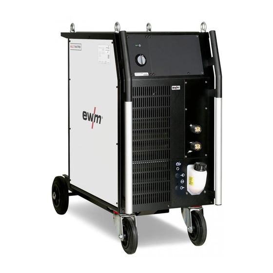
Page 18: Machine Description - Quick Overview
Machine description – quick overview Front view Machine description – quick overview Front view Figure 4-1 099-004833-EW501 22.04.2013... - Page 19 Machine description – quick overview Front view Item Symbol Description Lifting lug Ready for operation signal light Signal light on when the machine is switched on and ready for operation Main switch, machine on/off Carrying handle Cooling air inlet Wheels, guide castors Coolant tank Coolant tank cap Automatic cut-out of coolant pump key button...
-
Page 20: Rear View
Machine description – quick overview Rear view Rear view Figure 4-2 099-004833-EW501 22.04.2013... - Page 21 Machine description – quick overview Rear view Item Symbol Description 7-pole connection socket (digital) For connecting digital accessory components 7-pole connection socket (digital) Wire feed unit connection PC interface, serial (D-Sub connection socket, 9-pole) 19-pole mechanised welding interface (analogue) (See chapter entitled "Design and function > interfaces".) analog Connection socket, “+”...
-
Page 22: Machine Control - Operating Elements
Machine description – quick overview Machine control – Operating elements Machine control – Operating elements 500A 49.9V Job Nr Hold Expert SG2/3 MIG/MAG Mode Spezial 100% G3/4 Si1 GMAW MSG-Löten Ar/CO CrNi 80-90% Ar GMA-Brazing Ar/O Auftragsschw. CuSi Ar/CO /O 91-99% Ar GMA-Surfacing CuAl... - Page 23 Machine description – quick overview Machine control – Operating elements Item Symbol Description Gas type selection push-button 100% carbon dioxide Ar/CO Argon and carbon dioxide mixture Ar/O Argon and oxygen mixture Ar/CO Argon, carbon dioxide and oxygen mixture 100% Argon Ar/N Argon and nitrogen mixture Ar/He/N...
-
Page 24: Design And Function
Design and function General Design and function General WARNING Risk of injury from electric shock! Contact with live parts, e.g. welding current sockets, is potentially fatal! • Follow safety instructions on the opening pages of the operating instructions. • Commissioning may only be carried out by persons who have the relevant expertise of working with arc welding machines! •... -
Page 25: Installation
Design and function Installation CAUTION Damage due to incorrect connection! Accessory components and the power source itself can be damaged by incorrect connection! • Only insert and lock accessory components into the relevant connection socket when the machine is switched off. •... -
Page 26: Notes On The Installation Of Welding Current Leads
Design and function Notes on the installation of welding current leads Notes on the installation of welding current leads NOTE Incorrectly installed welding current leads can cause faults in the arc (flickering). Install welding lead and hose package in parallel and as close together as possible. Keep the welding lead and hose packages of each welding machine separate, with an installation distance of at least 15 cm! Fully unroll welding current leads, torch hose packages and intermediate hose... -
Page 27: Welding Torch Cooling System
Design and function Welding torch cooling system Welding torch cooling system 5.6.1 General CAUTION Coolant mixtures! Mixtures with other liquids or the use of unsuitable coolants result in material damage and renders the manufacturer's warranty void! • Only use the coolant described in this manual (overview of coolants). •... -
Page 28: Adding Coolant
Design and function Welding torch cooling system 5.6.3 Adding coolant The unit is supplied ex works with a minimum level of coolant. NOTE After the initial filling, wait for at least one minute when the machine is switched on so that the hose package is filled with coolant completely and without bubbles. -
Page 29: Mains Connection
Design and function Mains connection Mains connection DANGER Hazard caused by improper mains connection! An improper mains connection can cause injuries or damage property! • Only use machine with a plug socket that has a correctly fitted protective conductor. • If a mains plug must be fitted, this may only be carried out by an electrician in accordance with the relevant national provisions or regulations! •... -
Page 30: Intermediate Hose Package Connection
Design and function Intermediate hose package connection Intermediate hose package connection NOTE Note the polarity of the welding current! Some wire electrodes (e.g. self-shielding cored wire) are welded using negative polarity. In this case, the welding current lead should be connected to the "-" welding current socket, and the workpiece lead should be connected to the "+"... -
Page 31: Shielding Gas Supply (Shielding Gas Cylinder For Welding Machine)
Design and function Shielding gas supply (shielding gas cylinder for welding machine) • Insert the end of the hose package through the strain relief of the hose package and lock by turning to the right. • Insert the plug on the welding current lead into the welding current connection socket "+" and lock. •... - Page 32 Design and function Shielding gas supply (shielding gas cylinder for welding machine) Figure 5-5 Item Symbol Description Pressure regulator Shielding gas cylinder Output side of the pressure regulator Cylinder valve • Place the shielding gas cylinder into the relevant cylinder bracket. •...
-
Page 33: Mig/Mag Welding
Design and function MIG/MAG welding 5.10 MIG/MAG welding 5.10.1 Connection for workpiece lead NOTE Note the polarity of the welding current! Some wire electrodes (e.g. self-shielding cored wire) are welded using negative polarity. In this case, the welding current lead should be connected to the "-" welding current socket, and the workpiece lead should be connected to the "+"... -
Page 34: Definition Of Mig/Mag Welding Tasks
Design and function MIG/MAG welding 5.10.2 Definition of MIG/MAG welding tasks This machine range features simple operation with a very wide range of functions. • Various JOBs (i.e. welding tasks consisting of welding process, material type, wire diameter and shielding gas type) have been pre-defined (see appendix for a list of JOBs). •... - Page 35 Design and function MIG/MAG welding Operating Action Result element Select welding process The signal light indicates the selection. Select material type The signal light indicates the selection. Select wire diameter The signal light indicates the selection. Select gas type The signal light indicates the selection. Select operating mode Select welding type Switch superpulses on or off...
-
Page 36: M3.19 Welding Machine Control And M3.70 Wire Feed Unit Control
Design and function MIG/MAG welding 5.10.3.2 M3.19 welding machine control and M3.70 wire feed unit control Super- puls Superpuls m/min DY N m/min Figure 5-8 099-004833-EW501 22.04.2013... - Page 37 Design and function MIG/MAG welding Operating Action Result element Select welding process The signal light indicates the selection. Select material type The signal light indicates the selection. Select wire diameter The signal light indicates the selection. Select gas type The signal light indicates the selection. Select operating mode The LED displays the selected operating mode.
-
Page 38: Burn-Back
Design and function MIG/MAG welding 5.10.3.3 Burn-back NOTE Prevents fusing of the wire electrode in the weld pool. Back-burn set too high: • Large ball formation of the wire electrode (poor re-ignition) • Wire electrode sticks in the gas nozzle. Back-burn set too low: •... -
Page 39: Mig/Mag Operating Point
Design and function MIG/MAG welding 5.10.4 MIG/MAG operating point The operating point (welding output) is specified using the principle of MIG/MAG one-dial operation, i.e. the user need only specify the operating point by setting the required wire speed, for example, and the digital system will calculate the optimum values for welding current and voltage (operating point). -
Page 40: Operating Point Setting Using Material Thickness
Design and function MIG/MAG welding 5.10.4.2 Operating point setting using material thickness NOTE The settings are made on the wire feed unit control. M3.00 The process of setting the operating point is described below as an example by means of setting the panel thickness parameter. -
Page 41: Accessory Components For Operating Point Setting
Design and function MIG/MAG welding 5.10.4.4 Accessory components for operating point setting The operating point can also be set with various accessory components such as • remote controls • special torches • PC software • robot and industrial bus interfaces (optional mechanised welding interface required – not possible for all machines in this series!) You will find an overview of accessory components in the "Accessories"... -
Page 42: Mig/Mag Functional Sequences / Operating Modes
Design and function MIG/MAG welding 5.10.6 MIG/MAG functional sequences / operating modes NOTE There are optimum pre-sets for welding parameters such as gas pre-flow and burn back, etc. for numerous applications (although these can also be changed if required). 5.10.6.1 Explanation of signs and functions Symbol Meaning Press torch trigger... - Page 43 Design and function MIG/MAG welding Non-latched mode Figure 5-10 Step 1 • Press and hold torch trigger. • Shielding gas is expelled (gas pre-flows). • Wire feed motor runs at “creep speed”. • Arc ignites after the wire electrode makes contact with the workpiece; welding current flows. •...
- Page 44 Design and function MIG/MAG welding Non-latched operation with superpulse Figure 5-11 Step 1 • Press and hold torch trigger. • Shielding gas is expelled (gas pre-flows). • Wire feed motor runs at “creep speed”. • Arc ignites after the wire electrode makes contact with the workpiece; welding current flows. •...
- Page 45 Design and function MIG/MAG welding Special, non-latched START Figure 5-12 Step 1 • Press and hold torch trigger • Shielding gas is expelled (gas pre-flows) • Wire feed motor runs at “creep speed”. • Arc ignites after the wire electrode makes contact with the workpiece, welding current is flowing (start program P for the time t START...
- Page 46 Design and function MIG/MAG welding Spot welding START Figure 5-13 NOTE The ignition time t must be added to the spot time t start 1st cycle • Press and hold torch trigger • Shielding gas is expelled (gas pre-flows) • Wire feed motor runs at "creep speed"...
- Page 47 Design and function MIG/MAG welding Special, non-latched with superpulse START Figure 5-14 Step 1 • Press and hold torch trigger • Shielding gas is expelled (gas pre-flows) • Wire feed motor runs at “creep speed”. • Arc ignites after the wire electrode makes contact with the workpiece, welding current is flowing (start program P for the time t START...
- Page 48 Design and function MIG/MAG welding Latched mode Figure 5-15 Step 1 • Press and hold torch trigger • Shielding gas is expelled (gas pre-flows) • Wire feed motor runs at “creep speed”. • Arc ignites after the wire electrode makes contact with the workpiece; welding current flows. •...
- Page 49 Design and function MIG/MAG welding Latched mode with superpulse Figure 5-16 Step 1: • Press and hold torch trigger • Shielding gas is expelled (gas pre-flows) • Wire feed motor runs at “creep speed”. • Arc ignites after the wire electrode makes contact with the workpiece; welding current flows. •...
- Page 50 Design and function MIG/MAG welding Latched with changing welding method (process switching) Figure 5-17 1st cycle: • Press and hold torch trigger • Shielding gas is expelled (gas pre-flows) • Wire feed motor runs at "creep speed" • Arc ignites after the wire electrode makes contact with the workpiece; welding current flows •...
- Page 51 Design and function MIG/MAG welding Latched special START Figure 5-18 Step 1 • Press and hold torch trigger • Shielding gas is expelled (gas pre-flows) • Wire feed motor runs at “creep speed”. • Arc ignites after the wire electrode makes contact with the workpiece, welding current is flowing (start program P START Step 2...
- Page 52 Design and function MIG/MAG welding Special latched with changing welding method by tapping (process switching) START Figure 5-19 1st cycle • Press and hold torch trigger. • Shielding gas is expelled (gas pre-flows) • Wire feed motor runs at "creep speed" •...
- Page 53 Design and function MIG/MAG welding Special latched with changing welding method (process switching) START Figure 5-20 1st cycle • Press and hold torch trigger • Shielding gas is expelled (gas pre-flows) • Wire feed motor runs at "creep speed" • Arc ignites after the wire electrode makes contact with the workpiece, welding current is flowing (start program P for the time t...
-
Page 54: Mig/Mag Automatic Cut-Out
Design and function MIG/MAG welding Special, latched with superpulse START Figure 5-21 Step 1 • Press and hold torch trigger • Shielding gas is expelled (gas pre-flows) • Wire feed motor runs at “creep speed”. • Arc ignites after the wire electrode makes contact with the workpiece, welding current is flowing (start program P for the time t START... -
Page 55: Rootarc
Design and function MIG/MAG welding 5.10.7 rootArc Short arc with easy weld modelling capabilities for effortless gap bridging and positional welding. Figure 5-22 • Reduced spatter compared to standard short arc • Good root formation and secure sidewall fusion • Un-alloyed and low-alloy steels •... -
Page 56: Forcearc
Design and function MIG/MAG welding 5.10.8 forceArc Heat-reduced, directionally stable and powerful arc with deep penetration for the upper power range. Figure 5-23 • Smaller included angle due to deep penetration and directionally stable arc • Excellent root and sidewall fusion •... -
Page 57: Mig/Mag Program Sequence ("Program Steps" Mode)
Design and function MIG/MAG welding 5.10.9 MIG/MAG program sequence ("Program steps" mode) Certain materials, such as aluminium, require special functions in order to be able to weld them safely and at high quality. The latched special operating mode is used here with the following programs: •... -
Page 58: Mig/Mag Overview Of Parameters For M3.19
Design and function MIG/MAG welding 5.10.9.2 MIG/MAG overview of parameters for M3.19 START DVstart Ustart DVend Uend tstart tend Figure 5-25 Basic parameters Display Meaning/explanation Setting range GASstr Gas pre-flow time 0.0s to 20.0s "P " start program START DVstr (r) Wire-feed speed, relative 1% to 200% DVstr (a) -
Page 59: Example, Tack Welding (Non-Latched)
Design and function MIG/MAG welding 5.10.9.3 Example, tack welding (non-latched) Figure 5-26 Basic parameters Parameter Meaning / explanation Setting range GASstr Gas pre-flow time 0.0s to 20.0s GASend: Gas post-flow time 0.0s to 20s RUECK Wire burn-back length 2 to 500 "P "... -
Page 60: Example, Aluminium Welding (Latched Special)
Design and function MIG/MAG welding 5.10.9.5 Example, aluminium welding (latched special) START Figure 5-28 Basic parameters Welding parameter Meaning / explanation Setting range GASstr Gas pre-flow time 0.0s to 20.0s GASend: Gas post-flow time 0.0s to 20.0s RUECK Wire burn-back length 2 to 500 "P "... -
Page 61: Example, Visible Seams (Latched Super Pulse)
Design and function MIG/MAG welding 5.10.9.6 Example, visible seams (latched super pulse) START Figure 5-29 Basic parameters Welding parameter Meaning / explanation Setting range GASstr Gas pre-flow time 0.0s to 20.0s GASend: Gas post-flow time 0.0s to 20.0s RUECK Wire burn-back length 2 to 500 PROC.SP. -
Page 62: Process Switching Configuration
Design and function MIG/MAG welding 5.10.10 Process switching configuration START Figure 5-30 Parameter Program Setting option Applies to operating mode: Welding process switching Non-latched/latched operation with changing welding processes If P involves a standard arc welding process, the operating mode switches Special non-latched/latched operation into the pulsed arc process and vice with changing welding processes... -
Page 63: Main Program A Mode
Design and function MIG/MAG welding 5.10.11 Main program A mode Different welding tasks or positions on a workpiece demand various welding performances (operating points) or welding programs. The following parameters are stored in each of the up to 16 programs: •... - Page 64 Design and function MIG/MAG welding Example 1: Welding workpieces with different sheet metal thicknesses (non-latched) Figure 5-31 Example 2: Welding different positions on a workpiece (latched) Figure 5-32 Example 3: Aluminium welding of different sheet metal thicknesses (non-latched or latched special) Figure 5-33 NOTE...
-
Page 65: Selecting Parameters (Program A) Using Wire Feed Unit Control M3.19
Design and function MIG/MAG welding 5.10.11.1 Selecting parameters (program A) using wire feed unit control M3.19 Operating Action Result Display element Select main program A mode Program A Select the welding parameters using the buttons "Up" and "Down" (left) Change values for the selected welding parameter using the buttons "Up"... -
Page 66: Mig/Mag Overview Of Parameters For M3.19
Design and function MIG/MAG welding 5.10.11.3 MIG/MAG overview of parameters for M3.19 Different welding tasks or positions on a workpiece demand various welding outputs (operating points) or welding programs. For each program, the • Wire speed • Correction of the arc length and the •... -
Page 67: Mig/Mag Special-Torches
Design and function MIG/MAG welding 5.10.13 MIG/MAG special-torches NOTE When using a wire feed unit with the M3.00 control, not all special torches or special functions are available. Refer to the wire feed unit operating instructions for details. Function specifications and more indepth information can be found in the operating manual for the relevant welding torch! The following special torches can be used together with this welding machine: •... -
Page 68: Tig Welding
Design and function TIG welding 5.11 TIG welding 5.11.1 Welding torch connection NOTE TIG welding torches to be connected to a Euro torch connector are available in two versions: • TIG combi welding torches are connected to the Euro torch connector of the wire feeder and to the (-) welding current plug of the power source. -
Page 69: Connection For Workpiece Lead
Design and function TIG welding • Insert the central plug for the welding torch into the central connector and screw together with crown nut. • Insert the welding current plug of the combi welding torch into the (-) welding current connection socket and lock into place by turning to the right (only in case of a separate welding current connection). -
Page 70: Welding Task Selection
Design and function TIG welding 5.11.3 Welding task selection NOTE Selection of a welding task involves the interaction of the controls on the welding machine and the wire feed unit. After the basic settings are made on the welding machine, the operating point and other parameters can be set on the wire feed unit. 5.11.3.1 M3.19 welding machine control and M3.00 wire feed unit control 8 9 10 m/min... -
Page 71: M3.19 Welding Machine Control And M3.70 Wire Feed Unit Control
Design and function TIG welding 5.11.3.2 M3.19 welding machine control and M3.70 wire feed unit control m/min Figure 5-38 Operating Action Result Display element The various welding processes are run through The nominal values until the signal light for the required welding for the welding process comes on. -
Page 72: Tig Welding Data Display
Design and function TIG welding 5.11.4 TIG welding data display To the left and right of the control displays are the "Parameter selection" buttons ( ). They are used to select welding parameters to be displayed. Each press of the button advances the display to the next parameter (LEDs next to the button indicate the selection). -
Page 73: Pulses, Function Sequences
Design and function TIG welding 5.11.6 Pulses, function sequences 5.11.6.1 Explanation of signs and functions Symbol Meaning Press torch trigger Release torch trigger Tap torch trigger (press briefly and release) Shielding gas flowing Welding output Gas pre-flows Gas post-flows Non-latched Special, non-latched Latched Special, latched... - Page 74 Design and function TIG welding Non-latched mode Figure 5-41 Selection • Select non-latched operating mode Step 1 • Press and hold torch trigger. • Shielding gas is expelled (gas pre-flows). The arc is ignited using liftarc. • Welding current flows with pre-selected setting. Step 2 •...
- Page 75 Design and function TIG welding Latched mode Figure 5-43 Selection • Select latched operating mode Step 1 • Press and hold torch trigger • Shielding gas is expelled (gas pre-flows) The arc is ignited using liftarc. • Welding current flows with pre-selected setting. Step 2 •...
-
Page 76: Tig Automatic Cut-Out
Design and function TIG welding Latched special START Figure 5-44 Selection • Select latched special mode Step 1 • Press and hold torch trigger. • Shielding gas is expelled (gas pre-flows). The arc is ignited using liftarc. • Welding gas flows at pre-selected setting in start program "P ". -
Page 77: Tig Program Sequence ("Program Steps" Mode)
Design and function TIG welding 5.11.8 TIG program sequence ("Program steps" mode) 5.11.8.1 TIG parameter overview The parameter settings are made on welding machine control M3.19 START Istart Iend tstart tend Figure 5-45 Basic parameters Display Meaning/explanation Setting range GASstr Gas pre-flow time 0.0 s to 0.9 s GASend:... -
Page 78: Mma Welding
Design and function MMA welding 5.12 MMA welding CAUTION Risk of being crushed or burnt. When replacing spent or new stick electrodes • Switch off machine at the main switch • Wear appropriate safety gloves • Use insulated tongs to remove spent stick electrodes or to move welded workpieces and •... -
Page 79: Welding Task Selection
Design and function MMA welding 5.12.2 Welding task selection NOTE Selection of a welding task involves the interaction of the controls on the welding machine and the wire feed unit. After the basic settings are made on the welding machine, the operating point and other parameters can be set on the wire feed unit. 5.12.2.1 M3.19 welding machine control and M3.00 wire feed unit control 8 9 10 m/min... -
Page 80: M3.19 Welding Machine Control And M3.70 Wire Feed Unit Control
Design and function MMA welding 5.12.2.2 M3.19 welding machine control and M3.70 wire feed unit control m/min Figure 5-48 Operating Action Result Display element The various welding processes are run through The nominal values until the signal light for the required welding for the welding process comes on. -
Page 81: Mma Welding Data Display
Design and function MMA welding 5.12.3 MMA welding data display To the left and right of the LCD display on the control there are 2 “arrow keys” on each side for selecting the welding parameter to be displayed. The button is used to scroll through the parameters from the bottom upwards and the button is used to scroll downwards from the top. -
Page 82: Arcforce
Design and function MMA welding 5.12.4 Arcforce NOTE The settings are made on the wire feed unit control. M3.00 Result Display Operating Action element Arcforce setting for the different electrode No change types: Negative values: Rutile Values around zero: Basic Positive values: Cellulose M3.70... -
Page 83: Hotstart
Design and function MMA welding 5.12.5 Hotstart The hotstart device improves the ignition of the stick electrodes using an increased ignition current. a) = Hotstart time b) = Hotstart current Welding current Time Figure 5-50 5.12.5.1 Hotstart current and Hotstart time Control element Action Result Display... -
Page 84: Antistick
Design and function MMA welding 5.12.6 Antistick Anti-stick prevents the electrode from annealing. If the electrode sticks in spite of the Arcforce device, the machine automatically switches over to the minimum current within about 1 second to prevent the electrode from overheating. -
Page 85: Remote Control
Design and function Remote control 5.13 Remote control CAUTION Damage to the machine due to improper connection! The remote controls have been developed to be connected to welding machines or wire feed units only. Connecting them to other machines may cause damage to the machines! •... -
Page 86: Interfaces
Design and function Interfaces 5.14 Interfaces CAUTION Damage due to the use of non-genuine parts! The manufacturer's warranty becomes void if non-genuine parts are used! • Only use system components and options (power sources, welding torches, electrode holders, remote controls, spare parts and replacement parts, etc.) from our range of products! •... -
Page 87: Rint X12 Robot Interface
Design and function Interfaces 5.14.2 RINT X12 robot interface The standard digital interface for mechanised applications Functions and signals: • Digital inputs: start/stop, operating modes, JOB and program selection, inching, gas test • Analogue inputs: control voltages, e.g. for welding performance, welding current, etc. •... -
Page 88: Advanced Functions On The Welding Machine Control
Design and function Advanced functions on the welding machine control 5.15 Advanced functions on the welding machine control 5.15.1 Displaying JOB information (Job-Info) NOTE Information on the current JOB is displayed in this mode. • In JOBs 127 and 128 (TIG & MMA), it is not possible to select the mode as it would not be relevant. -
Page 89: Creating A New Job In The Memory Or Copying A Job
Design and function Advanced functions on the welding machine control 5.15.2.1 Creating a new JOB in the memory or copying a JOB It is normally possible to adjust all 256 JOBs individually. However, it is useful to issue a separate JOB number to special welding tasks. -
Page 90: Using Block Mode (Block Job)
Design and function Advanced functions on the welding machine control 5.15.2.4 Using Block mode (Block JOB) NOTE This function can only be properly used in combination with the M3.7x wire feeder control and one of the following welding torch types: •... -
Page 91: Resetting An Existing Job To The Factory Setting (Reset Job)
Design and function Advanced functions on the welding machine control Table: Program torch JOB assignment JOB no. Welding torch selection Control SP1 129 selection SP2 130 SP3 131 JOB "0" on the program torch: Setpoint values for wire speed, arc correction and dynamics are specified manually on the wire feed unit control. -
Page 92: Switching The Hold Function On And Off
Design and function Advanced functions on the welding machine control 5.15.3 Switching the Hold function on and off Operating Action Result Display element Select “Special Mode” Program steps Special Mode Hold-Fkt Select the Hold function using the buttons “Up” and “Down”... -
Page 93: Resetting Jobs To Status On Delivery (Reset All)
Design and function Operating time counter 5.15.5 Resetting JOBs to status on delivery (Reset ALL) This function is used to reset JOBs 1-128, 170-256 to the original status on delivery. JOBs 129-169 remain unchanged. Operating Action Result Display element Select “Special Mode” Program steps Special Mode Res. -
Page 94: Maintenance, Care And Disposal
Maintenance, care and disposal General Maintenance, care and disposal DANGER Risk of injury from electric shock! Cleaning machines that are not disconnected from the mains can lead to serious injuries! • Disconnect the machine completely from the mains. • Remove the mains plug! •... -
Page 95: Monthly Maintenance Tasks
Maintenance, care and disposal Maintenance work 6.2.2 Monthly maintenance tasks 6.2.2.1 Visual inspection • Casing damage (front, rear and side walls) • Wheels and their securing elements • Transport elements (strap, lifting lugs, handle) • Check coolant tubes and their connections for impurities 6.2.2.2 Functional test •... -
Page 96: Disposing Of Equipment
Information about giving back used equipment or about collections can be obtained from the respective municipal administration office. • EWM participates in an approved waste disposal and recycling system and is registered in the Used Electrical Equipment Register (EAR) under number WEEE DE 57686922. •... -
Page 97: Rectifying Faults
Rectifying faults Checklist for rectifying faults Rectifying faults All products are subject to rigorous production checks and final checks. If, despite this, something fails to work at any time, please check the product using the following flowchart. If none of the fault rectification procedures described leads to the correct functioning of the product, please inform your authorised dealer. -
Page 98: Error Messages (Power Source)
Rectifying faults Error messages (power source) Error messages (power source) NOTE A welding machine error is indicated by an error code being displayed (see table) on the display on the machine control. In the event of a machine error, the power unit is shut down. The display of possible error numbers depends on the machine version (interfaces/functions). -
Page 99: Interface For Automated Welding
Rectifying faults Error messages (power source) Legend for categories (error reset) a) The error message will disappear once the error has been rectified. b) The error message can be reset by pressing a key button: Welding machine control Key button RC1 / RC2 Expert CarExpert / Progress (M3.11) -
Page 100: Resetting Jobs (Welding Tasks) To The Factory Settings
Rectifying faults Resetting JOBs (welding tasks) to the factory settings Resetting JOBs (welding tasks) to the factory settings NOTE JOBs 1–128 and 170–256 will be reset. Custom JOBs 129–169 are maintained. Operating Action Result Display element Select “Special Mode” Program steps Special Mode Res. -
Page 101: Display Machine Control Software Version
Rectifying faults Display machine control software version Display machine control software version NOTE The query of the software versions only serves to inform the authorised service staff! Figure 7-1 Display Setting/selection List of the software Start of the automated process Software versions display ------- = System bus ID/printed circuit board... -
Page 102: Vent Coolant Circuit
Rectifying faults Vent coolant circuit Vent coolant circuit NOTE To vent the cooling system always use the blue coolant connection, which is located as deep as possible inside the system (close to the coolant tank)! blau / blue ca. 5s KLICK CLICK KLICK... -
Page 103: Technical Data
Technical data Phoenix 401 Expert puls FDW Technical data NOTE Performance specifications and guarantee only in connection with original spare and replacement parts! Phoenix 401 Expert puls FDW MIG/MAG 5 A–400 A Setting range for welding current 10.2 V–26.0 V 20.2 V–36.0 V 14.3 V–34.0 V Setting range for welding voltage... -
Page 104: Phoenix 351, 451, 551 Expert Puls Fdw
Technical data Phoenix 351, 451, 551 Expert puls FDW Phoenix 351, 451, 551 Expert puls FDW Setting range of welding current/voltage: 5 A/10.2 V to 5 A/10.2 V to 450 5 A/10.2 V to 550 350 A/24.0 V A/28.0 V A/32.0 V 5 A/20.2 V to 5 A/20.2 V to 450... -
Page 105: Accessories
Accessories System components Accessories NOTE Performance-dependent accessories like torches, workpiece leads, electrode holders or intermediate hose packages are available from your authorised dealer. System components Type Designation Item no. Phoenix Expert drive 4 M3.70 Wire feed unit, water, Euro central connector 090-004845-00502 Phoenix Expert drive 4L Wire feed unit, water, Euro central connector... -
Page 106: Remote Control/Connecting And Extension Cable
Accessories Remote control/connecting and extension cable Remote control/connecting and extension cable 9.4.1 7-pole connection Type Designation Item no. R40 7POL Remote control, 10 programs 090-008088-00000 R50 7POL Remote control, all welding machine functions can 090-008776-00000 be set directly at the workplace FRV 7POL 0.5 m Extension/connecting cable 092-000201-00004... -
Page 107: Job-List
Appendix A JOB-List Appendix A 10.1 JOB-List 099-004833-EW501 22.04.2013... - Page 108 Appendix A JOB-List 099-004833-EW501 22.04.2013...
- Page 109 Appendix A JOB-List 099-004833-EW501 22.04.2013...
- Page 110 Appendix A JOB-List 099-004833-EW501 22.04.2013...
- Page 111 Appendix A JOB-List 099-004833-EW501 22.04.2013...
- Page 112 Appendix A JOB-List 099-004833-EW501 22.04.2013...
- Page 113 Appendix A JOB-List 099-004833-EW501 22.04.2013...
- Page 114 Appendix A JOB-List 099-004833-EW501 22.04.2013...
- Page 115 Appendix A JOB-List 099-004833-EW501 22.04.2013...
-
Page 116: Overview Of Ewm Branches
90425 Nürnberg · Tel: +49 911 3841-727 · Fax: -728 www.ewm-automation.de · info@ewm-automation.de Sales and Service International EWM HIGHTEC WELDING GmbH EWM HIGHTEC WELDING Sales s.r.o. / Prodejní a poradenské centrum Fichtenweg 1 Tyršova 2106 4810 Gmunden · Austria · Tel: +43 7612 778 02-0 · Fax: -20 256 01 Benešov u Prahy ·...
Need help?
Do you have a question about the Phoenix 351 Expert puls FDW and is the answer not in the manual?
Questions and answers