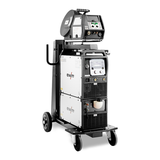
EWM Phoenix 355 Expert 2.0 puls MM TKM Operating Instructions Manual
Hide thumbs
Also See for Phoenix 355 Expert 2.0 puls MM TKM:
- Operating instructions manual (51 pages)

Subscribe to Our Youtube Channel
Related Manuals for EWM Phoenix 355 Expert 2.0 puls MM TKM


Summary of Contents for EWM Phoenix 355 Expert 2.0 puls MM TKM
- Page 1 Operating instructions Welding machine Phoenix 355 Expert 2.0 puls MM TKM 099-005445-EW501 Observe additional system documents! 07.11.2016...
-
Page 2: General Instructions
+49 2680 181-0. A list of authorised sales partners can be found at www.ewm-group.com. Liability relating to the operation of this equipment is restricted solely to the function of the equipment. -
Page 3: Table Of Contents
Contents Notes on the use of these operating instructions Contents 1 Contents ..............................3 2 For your safety ............................5 Notes on the use of these operating instructions ................5 2.1.1 Explanation of icons ....................... 6 Part of the complete documentation ....................7 Safety instructions .......................... - Page 4 General operating problems ......................46 7.2.1 Automation interface ..................... 46 8 Technical data............................47 Phoenix 355 Expert 2.0 puls MM TKM ..................47 9 Accessories ............................48 General accessories ........................48 Options ............................48 Remote control/connecting and extension cable ................. 49 9.3.1...
-
Page 5: For Your Safety
For your safety Notes on the use of these operating instructions For your safety Notes on the use of these operating instructions DANGER Working or operating procedures which must be closely observed to prevent imminent serious and even fatal injuries. •... -
Page 6: Explanation Of Icons
For your safety Notes on the use of these operating instructions 2.1.1 Explanation of icons Symbol Description Symbol Description Indicates technical aspects which the Activate and release/tap/tip user must observe. Switch off machine Release Switch on machine Press and keep pressed Switch Wrong Turn... -
Page 7: Part Of The Complete Documentation
For your safety Part of the complete documentation Part of the complete documentation These operating instructions are part of the complete documentation and valid only in combination with all other parts of these instructions! Read and observe the operating instructions for all system components, especially the safety instructions! The illustration shows a general example of a welding system. -
Page 8: Safety Instructions
For your safety Safety instructions Safety instructions WARNING Risk of accidents due to non-compliance with the safety instructions! Non-compliance with the safety instructions can be fatal! • Carefully read the safety instructions in this manual! • Observe the accident prevention regulations and any regional regulations! •... - Page 9 For your safety Safety instructions WARNING Risk of injury due to improper clothing! During arc welding, radiation, heat and voltage are sources of risk that cannot be avoided. The user has to be equipped with the complete personal protective equipment at all times.
- Page 10 For your safety Safety instructions CAUTION Smoke and gases! Smoke and gases can lead to breathing difficulties and poisoning. In addition, solvent vapour (chlorinated hydrocarbon) may be converted into poisonous phosgene due to the ultraviolet radiation of the arc! • Ensure that there is sufficient fresh air! •...
- Page 11 For your safety Safety instructions CAUTION Electromagnetic fields! The power source may cause electrical or electromagnetic fields to be produced which could affect the correct functioning of electronic equipment such as IT or CNC devices, telecommunication lines, power cables, signal lines and pacemakers. •...
-
Page 12: Transport And Installation
For your safety Transport and installation Transport and installation WARNING Risk of injury due to improper handling of shielding gas cylinders! Improper handling and insufficient securing of shielding gas cylinders can cause serious injuries! • Observe the instructions from the gas manufacturer and any relevant regulations concerning the use of compressed air! •... -
Page 13: Intended Use
In case of unauthorised changes, improper repairs, non-compliance with specified deadlines for "Arc Welding Equipment – Inspection and Testing during Operation", and/or prohibited modifications which have not been explicitly authorised by EWM, this declaration shall be voided. An original document of the specific declaration of conformity is included with every product. -
Page 14: Machine Description - Quick Overview
Machine description – quick overview Front view Machine description – quick overview Front view Figure 4-1 099-005445-EW501 07.11.2016... - Page 15 Machine description – quick overview Front view Item Symbol Description Carrying handle Transport bar Protective cap Cover for the wire feed mechanism and other operating elements. Depending on the machine series, additional stickers with information on the replacement parts and JOB lists will be located on the inside. Wire spool inspection window Check wire supply Slide latch, lock for the protective cap...
-
Page 16: Rear View
Machine description – quick overview Rear view Rear view Figure 4-2 Item Symbol Description Main switch, machine on/off Connecting nipple G¼, shielding gas connection 19-pole mechanised welding interface (analogue) > see 5.8 chapter Cooling air outlet External wire feed inlet Pre-cut casing inlet for external wire feed. -
Page 17: Operating Elements In The Machine
Machine description – quick overview Rear view 4.2.1 Operating elements in the machine Figure 4-3 Item Symbol Description Key button, automatic cutout Wire feed motor supply voltage fuse press to reset a triggered fuse Welding torch function changeover switch (special welding torch required) Changing over programs or JOBs Infinite adjustment of welding performance. -
Page 18: Design And Function
Design and function Transport and installation Design and function WARNING Risk of injury from electric shock! Contact with live parts, e.g. welding current sockets, is potentially fatal! • Follow safety instructions on the opening pages of the operating instructions. • Commissioning may only be carried out by persons who have the relevant expertise of working with arc welding machines! •... -
Page 19: Machine Cooling
Design and function Transport and installation 5.1.2 Machine cooling Insufficient ventilation results in a reduction in performance and equipment damage. • Observe the ambient conditions! • Keep the cooling air inlet and outlet clear! • Observe the minimum distance of 0.5 m from obstacles! 5.1.3 Workpiece lead, general CAUTION... -
Page 20: Notes On The Installation Of Welding Current Leads
Design and function Transport and installation 5.1.5 Notes on the installation of welding current leads Incorrectly installed welding current leads can cause faults in the arc (flickering). Lay the workpiece lead and hose package of power sources without HF igniter (MIG/MAG) for as long and as close as possible in parallel. -
Page 21: Stray Welding Currents
Design and function Transport and installation Fully unroll welding current leads, torch hose packages and intermediate hose packages. Avoid loops! Always keep leads as short as possible! Lay any excess cable lengths in meanders. Figure 5-4 5.1.5.1 Stray welding currents WARNING Risk of injury due to stray welding currents! Stray welding currents can destroy protective earth conductors, damage machines and... -
Page 22: Mains Connection
Design and function Transport and installation 5.1.6 Mains connection DANGER Hazards caused by improper mains connection! An improper mains connection can cause injuries or damage property! • Only operate machine using a socket that has correctly fitted protective earth. • The mains voltage indicated on the rating plate must match the supply voltage. -
Page 23: Shielding Gas Supply (Shielding Gas Cylinder For Welding Machine)
Design and function Shielding gas supply (shielding gas cylinder for welding machine) Shielding gas supply (shielding gas cylinder for welding machine) WARNING Risk of injury due to improper handling of shielding gas cylinders! Improper handling and insufficient securing of shielding gas cylinders can cause serious injuries! •... -
Page 24: Shielding Gas Hose Connection
Design and function Shielding gas supply (shielding gas cylinder for welding machine) 5.2.2 Shielding gas hose connection Figure 5-8 Item Symbol Description Connecting nipple G¼, shielding gas connection • Connect crown nut of the shielding gas line to the G¼“ connecting nipple. 099-005445-EW501 07.11.2016... -
Page 25: Shielding Gas Volume Settings
Design and function Shielding gas supply (shielding gas cylinder for welding machine) 5.2.3 Shielding gas volume settings CAUTION Electric shocks! When setting the shielding gas quantity, high voltage ignition pulses or open circuit voltage are applied at the welding torch; these can lead to electric shocks and burning on contact. -
Page 26: Welding Torch Holder
Design and function Welding torch holder Welding torch holder The item described in the following is part of the machine´s scope of delivery. Figure 5-10 Item Symbol Description Crossmember of the transport handle Torch holder Fan-type lock washers Fixing screws (x 4) •... -
Page 27: Mig/Mag Welding
Design and function MIG/MAG welding MIG/MAG welding 5.4.1 Welding torch and workpiece line connection On delivery, the Euro torch connector is fitted with a capillary tube for welding torches with a steel liner. Conversion is necessary if a welding torch with a liner is used! •... - Page 28 Design and function MIG/MAG welding Figure 5-11 Item Symbol Description Welding torch Welding torch hose package Welding torch connection (Euro or Dinse torch connector) Welding current, shielding gas and torch trigger integrated 19-pole connection socket (analogue) Connection for welding torch control lead Welding current cable, polarity selection Welding current to central connection/torch.
-
Page 29: Wire Feed
Design and function MIG/MAG welding 5.4.2 Wire feed CAUTION Risk of injury due to moving parts! The wire feeders are equipped with moving parts, which can trap hands, hair, clothing or tools and thus injure persons! • Do not reach into rotating or moving parts or drive components! •... -
Page 30: Inserting The Wire Spool
Design and function MIG/MAG welding 5.4.2.2 Inserting the wire spool CAUTION Risk of injury due to incorrectly secured wire spool. If the wire spool is not secured properly, it may come loose from the wire spool support and fall to the ground, causing damage to the machine and injuries. •... -
Page 31: Changing The Wire Feed Rollers
Design and function MIG/MAG welding 5.4.2.3 Changing the wire feed rollers Figure 5-13 Item Symbol Description Tommy The tommy is used to secure the closure brackets of the wire feed rollers. Closure bracket The closure brackets are used to secure the wire feed rollers. Feed roll tensioner Fixing the clamping unit and setting the pressure. - Page 32 Design and function MIG/MAG welding Unsatisfactory welding results due to faulty wire feeding! The wire feed rolls must be suitable for the diameter of the wire and the material. The wire feed rolls are colour-coded to facilitate distinction (see the Wire feed roll overview table). When working with a wire diameter of >...
-
Page 33: Inching The Wire Electrode
Design and function MIG/MAG welding 5.4.2.4 Inching the wire electrode CAUTION Risk of injury due to welding wire escaping from the welding torch! The welding wire can escape from the welding torch at high speed and cause bodily injury including injuries to the face and eyes! •... -
Page 34: Spool Brake Setting
Design and function MIG/MAG welding A prerequisite for the automatic inching process is the correct preparation of the wire guide, especially in the capillary and wire guide tube area > see 5.4.1 chapter. • The contact pressure has to be adjusted separately for each side (wire inlet/outlet) at the feed roll tensioner setting nuts depending on the welding consumable used. -
Page 35: Tig Welding
Design and function TIG welding TIG welding 5.5.1 Welding torch and workpiece line connection Figure 5-17 Item Symbol Description Welding torch Welding torch hose package Welding torch connection (Euro or Dinse torch connector) Welding current, shielding gas and torch trigger integrated Welding current cable, polarity selection Welding current to the central connector/torch, enables polarity selection. -
Page 36: Welding Task Selection
Design and function TIG welding • Insert the central plug for the welding torch into the central connector and screw together with crown nut. • Insert the cable plug on the work piece lead into the "+" welding current connection socket and lock by turning to the right. -
Page 37: Mma Welding
Design and function MMA welding MMA welding CAUTION Risk of being crushed or burnt. When replacing spent or new stick electrodes • Switch off machine at the main switch • Wear appropriate safety gloves • Use insulated tongs to remove spent stick electrodes or to move welded workpieces and •... -
Page 38: Welding Task Selection
Design and function Remote control • Insert cable plug of the electrode holder into either the "+" or "-" welding current connection socket and lock by turning to the right. • Insert cable plug of the workpiece lead into either the "+" or "-" welding current connection socket and lock by turning to the right. -
Page 39: Interfaces For Automation
Design and function Interfaces for automation Interfaces for automation WARNING Do not carry out any unauthorised repairs or modifications! To avoid injury and equipment damage, the unit must only be repaired or modified by specialist, skilled persons! The warranty becomes null and void in the event of unauthorised interference. •... -
Page 40: Remote Control Connection Socket, 19-Pole
Design and function Interfaces for automation 5.8.2 Remote control connection socket, 19-pole Figure 5-19 Pos. Signal shape Designation Output Connection for cable screen (PE) Output Current flows signal I>0, galvanically isolated (max. +- 15V/100mA) Output Reference voltage for potentiometer 10V (max. 10mA) Input Control value specification for main current, 0-10V (0V = I , 10V =... -
Page 41: Rint X12 Robot Interface
Design and function PC interface 5.8.3 RINT X12 robot interface The standard digital interface for mechanised applications (optional, retrofitting on the machine or external fitting by the customer) Functions and signals: • Digital inputs: start/stop, operating modes, JOB and program selection, inching, gas test •... -
Page 42: Access Control
Design and function Access control 5.10 Access control The key switch is only available for machines which are fitted with the "OW KL XX5" option ex works. To protect against unauthorised or unintentional adjustment of the welding parameters on the machine, the control input can be locked with the aid of a key switch. -
Page 43: Maintenance, Care And Disposal
Maintenance, care and disposal General Maintenance, care and disposal General DANGER Incorrect maintenance and testing! The machine may be cleaned, repaired and tested by skilled and qualified personnel only. A qualified person is one who, due to their training, knowledge and experience, can detect any hazards and possible consequential damage when checking the machine, and can take the necessary safety measures. -
Page 44: Maintenance Work, Intervals
Maintenance, care and disposal Maintenance work, intervals Maintenance work, intervals Repair and maintenance work may only be performed by qualified authorised personnel; otherwise the right to claim under warranty is void. In all service matters, always consult the dealer who supplied the machine. -
Page 45: Annual Test (Inspection And Testing During Operation)
In addition to this, returns are also possible throughout Europe via EWM sales partners. Meeting the requirements of RoHS We, EWM AG in Mündersbach, Germany, hereby confirm that all products which we supply to you and that are subject to the RoHS directive comply with RoHS requirements (also see applicable EC directives on the Declaration of Conformity on your machine). -
Page 46: Rectifying Faults
Rectifying faults Checklist for rectifying faults Rectifying faults All products are subject to rigorous production checks and final checks. If, despite this, something fails to work at any time, please check the product using the following flowchart. If none of the fault rectification procedures described leads to the correct functioning of the product, please inform your authorised dealer. -
Page 47: Technical Data
Technical data Phoenix 355 Expert 2.0 puls MM TKM Technical data Performance specifications and guarantee only in connection with original spare and replacement parts! Phoenix 355 Expert 2.0 puls MM TKM MIG/MAG Setting range for welding current 5 A–350 A Setting range for welding voltage 14.3 V–31.5 V... -
Page 48: Accessories
Accessories General accessories Accessories Performance-dependent accessories like torches, workpiece leads, electrode holders or intermediate hose packages are available from your authorised dealer. General accessories Type Designation Item no. Trolly 55-5 Transport cart, assembled 090-008632-00000 Trolly 35.2-2 Transport vehicle 090-008296-00000 cool50 U40 Cooling module 090-008598-00502 voltConverter 230/400... -
Page 49: Remote Control/Connecting And Extension Cable
Accessories Remote control/connecting and extension cable Remote control/connecting and extension cable 9.3.1 7-pole connection Type Designation Item no. R40 7POL Remote control, 10 programs 090-008088-00000 R50 7POL Remote control, all welding machine functions can 090-008776-00000 be set directly at the workplace FRV 7POL 0.5 m Extension/connecting cable 092-000201-00004... -
Page 50: Replaceable Parts
Replaceable parts Wire feed rollers Replaceable parts The manufacturer's warranty becomes void if non-genuine parts are used! • Only use system components and options (power sources, welding torches, electrode holders, remote controls, spare parts and replacement parts, etc.) from our range of products! •... -
Page 51: 10.1.2 Wire Feed Rollers For Aluminium Wire
Replaceable parts Wire feed rollers 10.1.2 Wire feed rollers for aluminium wire Type Designation Item no. AL 4R 0.8 MM/0.03 INCH Drive roll set, 37 mm, for aluminium 092-002771-00008 WHITE AL 4R 1.0 MM/0.04 INCH Drive roll set, 37 mm, for aluminium 092-002771-00010 BLUE AL 4R 1.2 MM/0.045 INCH... -
Page 52: Overview Of Ewm Branches
Appendix A Overview of EWM branches Appendix A 11.1 Overview of EWM branches 099-005445-EW501 07.11.2016...
Need help?
Do you have a question about the Phoenix 355 Expert 2.0 puls MM TKM and is the answer not in the manual?
Questions and answers