Table of Contents
Advertisement
Quick Links
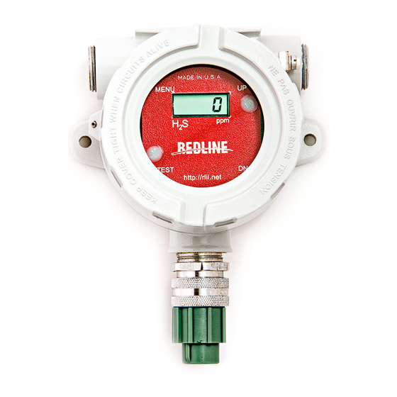
RL-101 Installation and Operation Manual
Power Consumption and Voltage rating
RL101 instrument is powered by 6 AA batteries
(9VDC) internally.
360uA continuous consumption when the device is
operational.
10350 STATE HWY 30 College Station, TX 77845
(979) 776-7200
IMPORTANT SAFETY WARNING
Failure to follow all safety and operational instructions
may result in instrument damage, serious injury or
death.
INSTRUMENT HOUSING
This product is housed in a Limatherm Instrument Housing
Type XD-Iwin
CL. I. GR. A,B,C,D; CL.II. GR. E,F,G CL.III; TYPE 4X
CL. ZONE 1 Ambient TEMP -40C to 85C
SAFETY MESSAGE
It is important to follow all instructions in this manual.
•
•
This device is to be installed by a trained professional
who is familiar with Redline Safety products.
Read and understand all instructions before installation
•
or use of this equipment.
Keep cover tight when circuits are alive.
•
•
Test Instrument regularly to ensure it is operating
properly.
1
Advertisement
Table of Contents

Related Manuals for Redline RL-101

Summary of Contents for Redline RL-101
- Page 1 Power Consumption and Voltage rating • This device is to be installed by a trained professional who is familiar with Redline Safety products. RL101 instrument is powered by 6 AA batteries (9VDC) internally. Read and understand all instructions before installation •...
-
Page 2: Operations Overview
5. Set Background Gas Level 6. Check Battery Voltage 7. Select Redline or WF784 Radio Message 8. Revision 9. Relay Test 10. Radio Signal Strength Input 11. Select Redline or WF784 Radio Message (same as step 7) 12. OFF 13. Startup... -
Page 3: Basic Operation
Basic Operation There are three main modes for the RL101 Head Unit. In addition, there is an OFF mode and a Startup mode. When the unit is powered, there is a 30 second (Startup) countdown during which some system values are displayed before going into the Normal Operating mode. -
Page 4: Normal Operation
1. Normal Operation The RL101 Head unit monitors the gas level. If the gas level is greater than or equal to the background setting, the unit will send a message every 5 seconds; if less than the background setting, the unit will send a message every 5 minutes. - Page 5 3. Calibration Use the Up and Down buttons to adjust the reading to match the value Press Menu button or of the calibration gas use reed switch twice to enter “CAL” mode To place the Rl101 into CAL Mode press the MENU button twice "CAL" will flash on the display. The RL101 Head unit monitors the gas level but does not send messages to the monitor when in CALIBRATION mode.
-
Page 6: Relay Test
(This mode is new to revisions 2.0 or greater). If the RL101 sensor head is in the wrong setting of 784, use the up or down buttons to change back to “Red”. ** if the RL101 sensor head is in 784 it will not communicate to the Redline Monitor** 8. Revision This mode shows the revision of the software that is being used in the RL101 Head unit. - Page 7 10. Radio Signal Strength Input To get to this mode press the TEST button twice and the MENU button twice "rIn" will then flash in the display. This mode allows the Head unit and Monitor to exchange messages (this mode is disabled when in the 784 mode since the 784 does not resend any messages).
-
Page 8: Installation
The Rl101 Head may be mounted 18 to 24 inches above the ground with the sensor housing pointed down towards the ground. For best signal strength position the glass window in line of sight of the Redline Monitor, also make sure there are no metal/nonmetal obstructions so signal will not be blocked. MAINTENANCE Redline Instruments recommends you check battery voltage every 90 days and Calibration of the head every 30 days.
Need help?
Do you have a question about the RL-101 and is the answer not in the manual?
Questions and answers